Research facilities and highlights at the Centro Nacional de Aceleradores (CNA) - ResearchGate
←
→
Page content transcription
If your browser does not render page correctly, please read the page content below
Eur. Phys. J. Plus     (2021) 136:273
https://doi.org/10.1140/epjp/s13360-021-01253-x

 Regular Article

Research facilities and highlights at the Centro Nacional
de Aceleradores (CNA)

J. Gómez-Camacho1,2,a , J. García López1,2 , C. Guerrero1,2 ,
J. M. López Gutiérrez1,3 , R. García-Tenorio1,4 , F. J. Santos-Arévalo1, E. Chamizo1,
F. J. Ferrer1, M. C. Jiménez-Ramos1, M. Balcerzyk1,5 , B. Fernández1,2
1 Centro Nacional de Aceleradores (U. Sevilla, J. Andalucía, CSIC), Avda Tomas A Edison, 7, 41092 Sevilla,
 Spain
2 Departamento de FAMN, U. Sevilla, Aptdo 1065, 41012 Sevilla, Spain
3 Departamento de Física Aplicada I, Escuela Politécnica Superior, c/Virgen de África, 7, 41092 Sevilla, Spain

4 Departamento de Física Aplicada II, ETS Arquitectura, Avda. Reina Mercedes, 2, 41012 Sevilla, Spain
5 Departamento de Fisiología Médica y Biofísica, Facultad de Medicina, Universidad de Sevilla, Avda. Sánchez
 Pizjuan, s/n, 41009 Sevilla, Spain

Received: 26 November 2020 / Accepted: 18 February 2021
© The Author(s) 2021

Abstract The Centro Nacional de Aceleradores is a user-oriented accelerator facility in
Seville, Spain. Its main facilities are a 3 MV tandem accelerator, an 18 MeV proton Cyclotron,
a tandetron used for AMS, a compact accelerator used for radiocarbon measurements, a 60 Co
irradiator and a PET/CT scanner. The technical specifications and research applications of
these facilities are described. A neutron beam line associated to a charged pulsed beam in the
tandem allows for time of flight measurements which determine the neutron energy. The use
of an adequate stripper gas in the AMS tandetron permits to measure heavy radionuclides with
very low detection levels, allowing to perform environmental studies using these radionu-
clides as tracers. The use of the microbeam in the tandem accelerator allows to apply the
ion beam-induced current technique to investigate the spectroscopic properties and radiation
hardness of different semiconductor detectors.

1 Introduction

The Centro Nacional de Aceleradores (CNA) is a joint research center of the University of
Seville, the regional government of Andalucía and the Spanish National Research Council
CSIC. It is recognized by the Spanish government as a Singular Scientific-Technical Facility,
ICTS, dedicated to interdisciplinary research and open to external users. It has six major
facilities: a Van de Graaff 3 MV Tandem accelerator, a 18/9 MeV Cyclotron accelerator,
an Accelerator 1MV Mass Spectrometer, a PET / CT scanner, a radiocarbon dating system
called MiCaDaS and a 60 Co Irradiator.
   The application of these 6 infrastructures covers fields as diverse as material sciences,
environmental impact, nuclear and particle physics, nuclear instrumentation, medical imag-

a e-mail: gomez@us.es (corresponding author)

                                            0123456789().: V,-vol                                123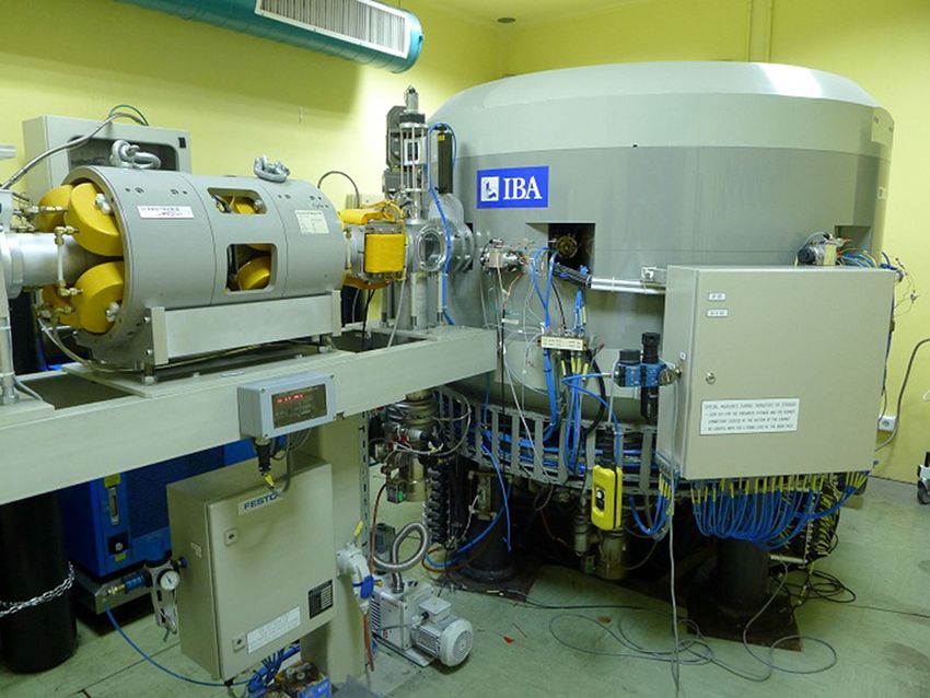
273 Page 2 of 16 Eur. Phys. J. Plus (2021) 136:273
ing, biomedical research and preclinical molecular imaging, 14 C dating and irradiation in
samples of technological and biological interest, among others.
CNA has a staff of about 57 from which 28 are PhD researchers, 18 technicians and 11
are PhD students. CNA has an external scientific committee, which advises on the scientific
policy of the centre, and informs the proposals submitted by external users. The number of
beam time applications carried our each year is about 100. The number of ISI papers per year
is about 35 and the number of PhD thesis is 2–3. CNA funds come from the patron institutions,
contracts with private companies and infrastructure and research projects. The local group
of CNA, constituted by 28 PhD researchers and their students, develops a vigorous research
activity, both at CNA and in international centres, obtains competitive research funds coming
from European, national and regional projects and successfully collaborates with the external
users.
2 Major facilities at CNA
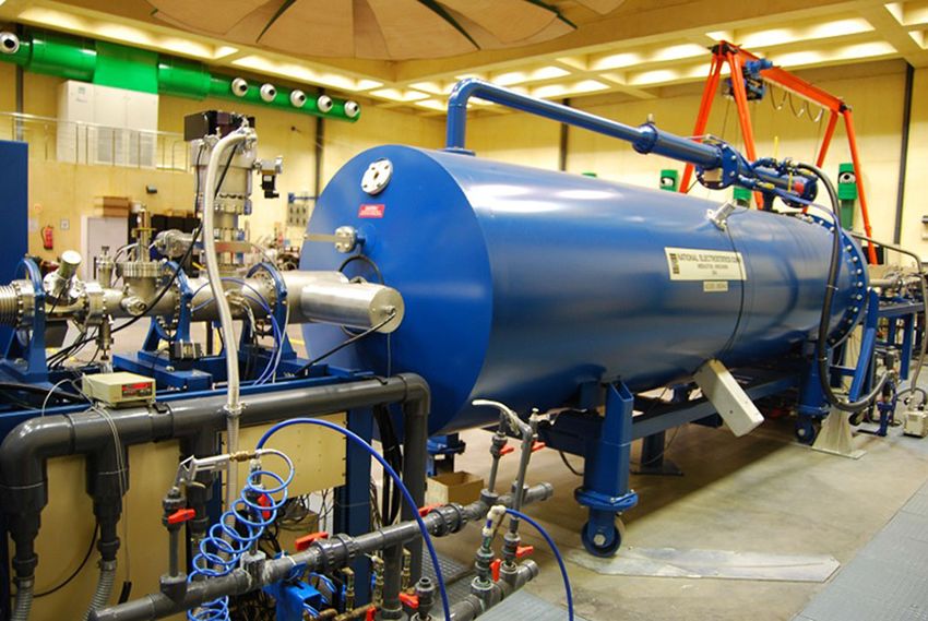
2.1 Tandem accelerator of 3 MV
The Tandem Accelerator, which was installed in 1998, was the first ion beam accelerator
in Spain. It is a Pelletron 3 MV Tandem, model 9SDH-2, manufactured by National Elec-
trostatics Corporation (NEC) which is capable of accelerating virtually all types of stable
ions by applying a large potential difference of up to 3 million volts (MV). This machine is
employed for characterization and modification of materials by means of ion beam analytical
(IBA) techniques and ion implantation, as well as for the study and development of nuclear
instrumentation, especially radiation detectors.
Negative ions are produced by three ion sources: (i) The Alphatross source is based on
radiofrequency techniques and generates negative ions from gases (H, He, N,…) in conjunc-
tion with an Rb charge-exchange channel. (ii) The SNICS II is a Cs sputtering source capable
of producing tens of µA of negative ions from solid targets. (iii) The Duoplasmatron source,
with a displaced intermediate (zwischen) electrode, provides modest currents of negative
ions (H− , C− , O− ) with a high-brightness, which is especially important for microbeam
applications. The ion sources are connected to an injection magnet that selects the desired
ion mass and directs the singly charged negative ions towards the entrance of the 3 MV
Tandem. Using a charge-changing process in the terminal, based on low pressure N2 gas, the
ions are accelerated through the same high potential twice.
The beam transport system includes elements for focusing (magnetic quadrupoles and
electrostatic lens), steering and monitoring (Beam Profile Monitors, Faraday Cups) the beam,
a Wien filter and a 90 degrees analyzing magnet. At the end of the line, the beam can pass
directly to the 0-degree line or can be deflected by a switch magnet with seven ports (Fig. 1).
At the present time, the 3 MV Tandem accelerator has eight available beamlines or exper-
imental chambers.
1. Nuclear physics beam line This line includes a high-volume vacuum chamber, where
nuclear instrumentation (detectors, electronics, etc), that will be used in international
Nuclear Physics facilities, can be developed and tested [1].
2. Microbeam chamber Manufactured by Oxford Microbeam Ltd., in this line it is possible
to focus the beam down to size of a few microns using a magnetic quadrupole triplet. The
scanning system, synchronized with the data acquisition, allows the formation of maps
from different signals with a maximum size of a few mm2 . One of our main research lines
123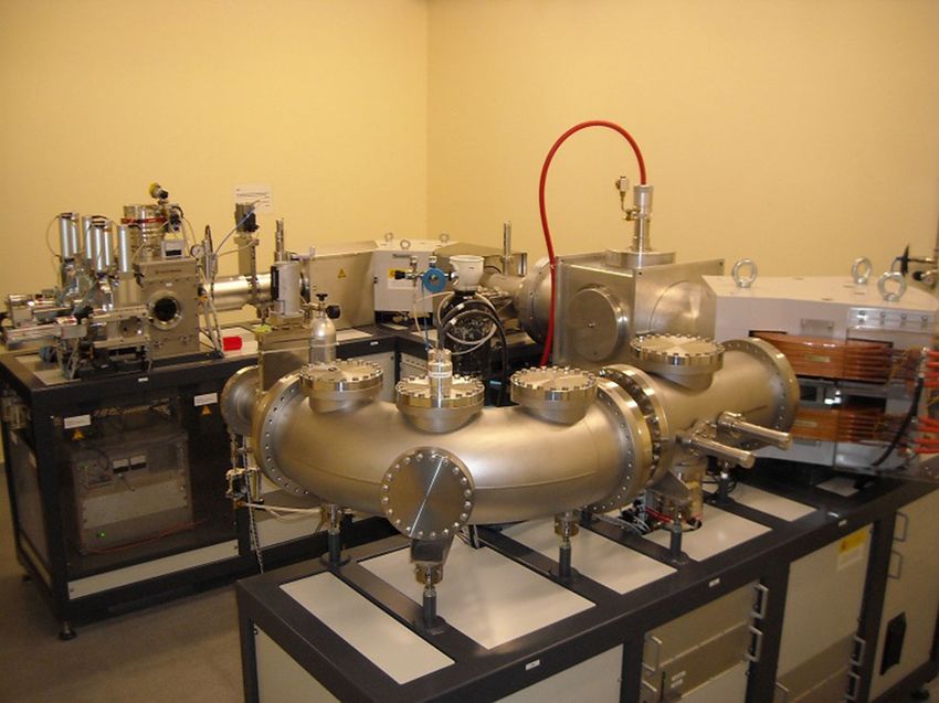
Eur. Phys. J. Plus   (2021) 136:273                                    Page 3 of 16   273

Fig. 1 Tandem accelerator

     is the analysis by PIXE and RBS of the actinide elemental distribution in microscopic
     particles originating from the hydrogen bombs involved in several nuclear accidents [2],
     where the results are similar to those obtained by confocal X-Ray fluorescence (XRF) in
     a synchrotron facility.
3.   Multipurpose IBA chamber This chamber is equipped with a set of particle, gamma
     and X-Ray detectors and a large target holder to carry out simultaneously different IBA
     experiments (RBS, PIXE, NRA and PIGE). In this chamber, we have recently investigated
     the use of novel solid 4 He targets for experimental studies on nuclear reactions [3,4], the
     composition of solid-state hole conductor in solar cells prepared by vacuum processing [5]
     and a novel ionizing particle detector based on thin films multilayers [6,7].
4.   Ionoluminescence chamber Located behind the multipurpose chamber, this vacuum
     chamber has black coating walls and is equipped with a heatable sample holder up to
     500 ◦ C and a photonic diagnostic system that allows mainly ionoluminescence studies.
     The first application of the chamber has been the characterization of different scintillator
     materials used for fast-ion loss detectors in nuclear fusion reactors [8].
5.   Irradiation chamber This beamline has been designed to allow the irradiation of large
     areas (up to 16×20 cm2 ) by raster scanning of the beam through magnetic deflection. It is
     mainly used by companies and research centers to perform irradiation tests of electronic
     devices and to test radiation detectors [9].
6.   Channeling chamber Manufactured by Charles–Evans, this line is dedicated to channel-
     ing analysis of single crystalline samples using a 4-axis goniometer. A parallel beam is
     obtained with a telescopic system formed by two sets of slits. The chamber is equipped
     with particle, X-Ray and γ -Ray detectors. Through experiments in the implantation and
     channeling beamlines, we have recently studied the formation of magnetic SiC substrates
     for spintronic applications [10].
7.   External beam This line is mainly used for Cultural heritage studies, since the use of in-air
     ion beam techniques (in combination with a good lateral resolution) presents numerous
     advantages for the analysis of inhomogeneous objects. The use of some elements pur-
     chased from Oxford Microbeams, like a magnetic quadrupole doublet, a precision four-
     jaw object slit and an exit nozzle set with micrometer adjustment, allow to obtain a spatial

                                                                                       123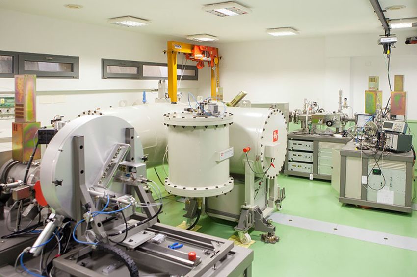
273   Page 4 of 16                                 Eur. Phys. J. Plus   (2021) 136:273

   resolution of about 60 µm. Recent applications include the study of the manufacturing
   of gold jewels of the Carambolo treasure [11] and of gold electroplating techniques on
   silver substrates [12]
8. HiSPANoS line HiSPANoS, from Hispalis Neutron Source, is the first accelerator-
   based neutron source in Spain. At HiSPANoS, neutrons are produced in a high-energy
   range covering from thermal to fast neutrons up to 9 MeV through the reactions
   p(7 Li, n), d(7 Li, n), d(D, n), p(9 Be, n) and d(9 Be, n). The main research application
   of the new neutron source is related to astrophysics, medical physics, detector charac-
   terization, electrical devices irradiation for aerospace purposes and neutron radiography,
   among others. In 2018, a buncher and chopper system and a new experimental line ded-
   icated to neutron time of flight (TOF) measurements were installed. The pulsing system
   was designed to produce protons and deuterons pulsed beams with a pulse width of 1–2
   ns at the target position at a frequency that can be varied from 32.5 kHz to 2 MHz [13].

2.2 18/9 MeV Cyclotron accelerator

Installed in 2004, the 18/9 Cyclotron, manufactured by Ion Beam Applications (IBA, Bel-
gium) was the second particle accelerator at CNA (Fig. 2). The Cyclone 18/9 accelerates
protons and deuterons to 18 and 9 MeV, respectively. Seven out of the eight targets are
devoted to the production of positron emitters, while in the eighth port an external beam-
line has been installed to perform experiments in Nuclear Physics. The extracted maximum
beam intensities in the internal target ports are 80 µA for protons and 35 µA for deuterons.
Moreover, it is possible to use the Dual Beam Mode, which consists in the simultaneous
bombardment with the same particle of two targets that are located in opposite positions.
    Positron emitting isotopes 18 F, 11 C, 13 N, 15 O are produced in the cyclotron targets. CNA
can produce several other isotopes in liquid or gaseous targets within limits set by Span-
ish regulatory authority (Consejo de Seguridad Nuclear). The produced isotopes are trans-
ported by tubing to automated synthesis modules of radiopharmacy. CNA has an agreement
with Curium Pharma for the production of Positron Emission Tomography (PET) radio-
pharmaceuticals. Curium produces commercially [18 F]fluorodeoxyglucose ([18 F]FDG) and
[18 F]fluoromethylcholine for oncological studies, [18 F]fluorodopa for diagnosis of Parkin-
son’s disease and [18 F]florbetaben for diagnosis of Alzheimer’s disease. Except of the last
radiopharmaceutical, CNA has access to these for preclinical studies. In research part of
radiopharmacy [18 F]NaF for bone scans, [11 C]methionine ([11 C]Met), [18 F]fluorothymidine
([18 F]FLT) and [18 F]fluoromisonidazole ([18 F]FMISO) used in oncology diagnosis may be
produced for the use in clinical and preclinical studies. Their clinical use needs previous
approval of Spanish regulatory authority for the use in each considered patient. Research
compounds such as [18 F]NaBF4 [14,15], [18 F]Amylovis [16] and several others were pro-
duced in this radiopharmacy for preclinical use.
    In the external beam line of the cyclotron, we can do research which requires the use
of protons and deuterons with energies above 6 MeV, which is the maximum energy these
particles can reach in our 3 MV Tandem. The particle beam passes through a thin window
and goes to the air before impacting on the target. For material analysis, this presents some
advantages over the use of a vacuum chamber, such as the low background X-Ray spectra
obtained by PIXE technique, the higher X-ray production cross sections for K-lines of heavy
elements and the greatest depth of analysis [17,18]. On the other hand, the setup of some
irradiation experiments is simplified, the temperature reached at the target is lower than
working in vacuum, and the size of the samples to be irradiated is not limited by the dimensions
of the chamber. A very important detail is the internal coating, with a layer of graphite of few

123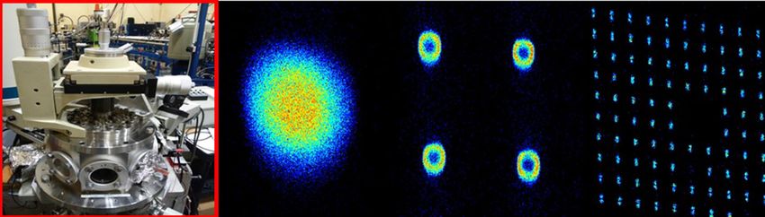
Eur. Phys. J. Plus    (2021) 136:273                                  Page 5 of 16   273

Fig. 2 Ciclotron accelerator

mm of thickness, of the metallic flange that forms the output window, to avoid its activation
during the experiments. A motorized table with step motors, remotely controlled, allows the
positioning of the targets with accuracy of 10 µm. Depending on the beam current intensity,
this is monitored by different methods: current integrator, ionization chamber, silicon particle
detector and radiochromic films. One of the advantages of the external line is its versatility; it
can be modified with the necessary elements for each investigation without much complexity.
For example, beam degraders, made of different materials and thicknesses, can be placed,
both in vacuum and in air, to irradiate the samples with different energies and beam sizes.

2.3 Accelerator 1MV Tandetron

The Accelerator Mass Spectrometry (AMS) system was acquired in 2005 from the Dutch
company High-Voltage Engineering Europe (HVEE). It is based on a 1 MV Tandetron accel-
erator (Fig. 3). AMS is an ultrasensitive technique dedicated to the detection of long-lived
radionuclides which are present in very low amounts in the analyzed samples and that are
beyond the scope of conventional radiometric and mass spectrometry techniques. Two prop-
erties give AMS this high sensitivity: First, molecules with the same mass as the isotope of
interest are broken in the interaction with the stripper gas in the accelerator terminal. Second,
using relatively high energies, the stopping power allows for additional isotope discrimi-
nation. Thanks to this, isotopic ratios as low as 14 C/12 C = 10−16 , 129 I/127 I = 10−14 or
10 Be/9 Be = 10−14 can be achieved.

    The 1MV AMS facility at CNA (SARA, from Spanish Accelerator for Radionuclide
Analysis) consists firstly on a Cesium sputtering ion source for solid samples. Ions from the
source are injected in the 1 MV tandem through an injection magnet which separates the
mass of interest. As described before, ions are stripped in the stripper channel, which is full
of He gas at low pressure. This has shown to provide a much higher transmission for several
isotopes than the original Ar specially in the case of the heaviest masses such as 129 I and
actinides. On the high energy side, the radioisotope of interest is conducted by an analyzing
magnet and an electrostatic deflector to an ionization chamber. Stable isotopes are measured

                                                                                      123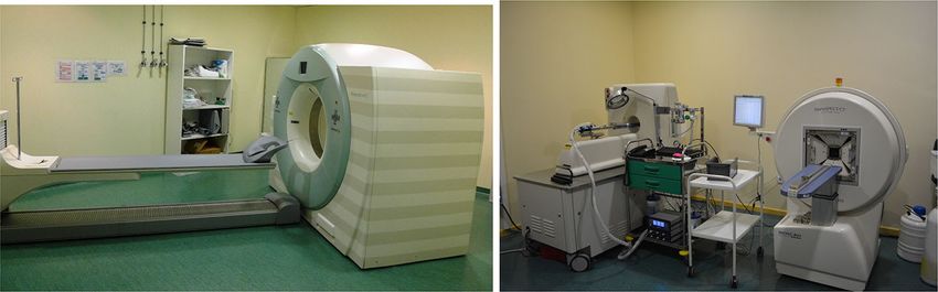
273   Page 6 of 16                                    Eur. Phys. J. Plus    (2021) 136:273

Fig. 3 AMS SARA accelerator

as an electric current after the magnet by a Faraday cup. Currently, 10 Be, 14 C, 26 Al, 41 Ca, 129 I
and several actinides can be routinely detected at SARA [19,20], which makes of this system
a very versatile tool. For this reason, it can be applied to very different fields. At CNA, one of
the most traditional and active lines is the study of environmental radioactivity. The ability
to detect very small amounts of radionuclides in samples as water, air or soil allows to trace
environmental processes. This can be applied not only to the distribution of radioactivity in
the Biosphere but also to diverse problems as climate change, geology, hydrology, etc. For
example, isotopes as 129 I or 236 U are being used at CNA to trace marine currents [21,22].
Also, sedimentation studies have been carried out through the measurement of 10 Be [23].
Apart from this, one of the latest applications of AMS at CNA is the characterization of
nuclear residues. Thanks to its high sensitivity, AMS can measure very small concentrations
of long-lived radionuclides in this kind of samples. This can help decide the final destination
of the residues, which is critical for security and economical costs.

2.4 MiCaDaS accelerator

Since 2012, 14 C Accelerator Mass Spectrometry measurements are performed in a dedicated
system at CNA (Fig. 4). This system is called MiCaDaS (Mini Carbon Dating System)
and was developed by the AMS group at the Ion Beam Physics Laboratory at the ETH
(Federal Institute of Technology) in Zürich, Switzerland [24]. It is based on a 200 kV tandem
Accelerator. This terminal voltage is five times lower than the nominal terminal voltage at
the analogue AMS system at CNA, SARA. It was designed for the exclusive detection of
14 C, being currently commercialized by the Swiss company Ionplus.

    As it was designed exclusively for 14 C measurement, several accessory focalization ele-
ments could be avoided, then reducing its size (only 2.6 × 3.4 m2 ) and turning it into a
simpler system. However, it follows the same structure of other AMS devices and is capable
to obtain comparable results to other AMS facilities [25]. Graphite cathodes are prepared
in the laboratory and ions are extracted in the ion source. After a first mass analysis, the
beam is introduced in the accelerator. Afterwards, ions with charge state q = 1+ are selected
at the high energy side, where the final analysis of the beam components is performed. An

123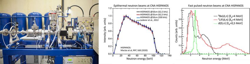
Eur. Phys. J. Plus   (2021) 136:273                                  Page 7 of 16   273

Fig. 4 MiCaDaS accelerator

ionization chamber gives information on the 14 C counts. As in other AMS systems, stable
isotopes are quantified in the corresponding Faraday cups.
   The MiCaDaS system includes a software package for sample preparation control. This
software also controls the creation of sample batches for measurement and data analysis. It
is optimized to work together with the AGE graphitization system, developed by the same
group.
   The very small sample amount needed permits Radiocarbon measurements performed
with MiCaDaS in a variety of fields. For example, one single seed, or 1 g of bone are
enough to get an accurate radiocarbon date. Then, it is easy to study archaelogical sites
extensively, getting many dates from the same site, and thus obtaining much more valuable
information [26]. The same can be applied to geological or environmental studies. As an
example, it is possible to obtain information about deposition rates in sediments and peats,
or information about landscape evolution [27] [28]. Also forensic applications have been
carried out by the measurement of 14 C, such as the dating of ivory samples against poaching
and ivory smuggling. The nuclear bomb testing in the mid-twentieth century, labeled all the
organic materials with very high 14 C concentrations. At CNA, this has been used to determine
whether the ivory used in a sculpture is old enough for the sculpture to be legally traded [29].

2.5 PET/CT clinical and preclinical scanners

Complementary to the particle accelerators described above, CNA has clinical and preclinical
scanners (Fig. 5). These instruments widen the research and applications scope of CNA and
benefit from multiple synergies, associated to common aspects in radioprotection, detector
technologies, production of novel PET isotopes the accelerators, etc. Research in this field is
carried out by a small group of CNA personnel, which collaborates with external users and
clinical personnel.
   Since late 2011, the National Accelerator Centre has a Clinical PET/CT, which allows
receiving patients at CNA facilities, particularly in the Diagnostic Imaging Center of CNA
(CDI). Human scanner shares its control room with that of a small animal PET and CT scanner.

                                                                                     123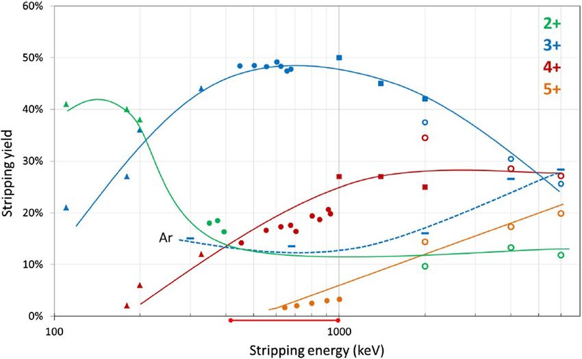
273   Page 8 of 16                                      Eur. Phys. J. Plus    (2021) 136:273

Fig. 5 Clinical PET-CT scanner (left) and preclinical micro-PET and nanoCT (right)

It is installed a few meters away from the radiopharmacy laboratory, which allows studies
with short half-life PET radioisotopes, such as 11 C-based radiopharmaceuticals. There is an
agreement with the Nuclear Medicine Services of the University Hospitals Virgen del Rocio
and Virgen Macarena to use and support the research facility in CNA. Presently, Hospital
patients of research interest are scanned at CNA three days per week, and for the remaining
two days the Service provides the qualified staff (Nuclear Medicine specialists, nursery
and technicians staff) for the human studies proposed by non-Hospital scientific personnel.
Moreover, the CT scanner is used for examination of art large objects and animals which due
to their size or mass do not fit in the animal scanner.
    Since 2005 CNA has a preclinical PET and CT scanners. Both PET and CT scanners can
operate in multibed mode allowing for large animal scans. Mosaic PET images and NanoCT
images can be co-registered in external PMOD software because the animal is immobilized
in the heated bed and can be transferred between these two scanners without moving it in
the bed. Dynamic and listmode PET images can be acquired in Mosaic PET. Clinical and
preclinical PET were used in numerous studies with animal models of acromegaly [30] with
[18 F]FDG and [11 C]Met, and of subarachnoid haemorrhage with [18 F]FMISO [31], in col-
laboration with IBIS (Spain). With CENTIS (Cuba) we examined [18 F]Amylovis, a potential
radiotracer for detection of β-Amyloid in Alzheimer’s disease [32]. Studies contributing to
the standardization of clinical PET/CT with [18 F]FDG [33] and of radiotherapy planning [34]
have been done. NanoCT was used for nanoparticle characterization in collaboration with
ICMSE (Spain) [35], and also for cryopreservation studies in collaboration with UCL (Bel-
gium) [36].

2.6 Co-60 irradiator

The proton and heavy ions irradiation research lines associated to the 3 MV Tandem and
18 MV Cyclotron accelerators were complemented in 2013 with the incorporation to CNA
of a system to perform irradiation studies with photons. This system, provided by Best
Theratronics limited (model Gammabeam X200), is equipped with a 60 Co source of 357
TBq (December 2013), which generates in air and at 100 cm distance a maximum kerma rate
of 103 Gy/h.
   With this new facility, the CNA in a first instance offers the possibility to perform reliability
studies of electronic components used in the aerospace industry, but due to the versatility of
the acquired system, it was possibly quickly to observe also the applicability of this irradiator
to Materials Science in studies devoted to analyze thermal, electric or mechanical properties
changes in materials allocated in radiation environments.

123
Eur. Phys. J. Plus (2021) 136:273 Page 9 of 16 273
The most recent applications of the CNA 60 Co irradiator have been mainly focussed in
to analyze dose effects in different electronic systems: unclonable functions implemented in
FPGAs [37] and SIMD microprocessors [38,39].
The CNA 60 Co irradiation facility is in accordance with the European Space Agency
Basic Specification ESCC 22900 (Total Dose Steady-State Irradiation Test Method), as well
as with the Defense Logistics Agency tests methods MIL-STD-750 1019 and MIL-STD-883
1019.
3 Research highlights
3.1 Pulsed neutron beams at HiSPANoS
The HiSPANoS neutron source features a number of neutron production mechanisms, as
summarized in Table 1. Using continuous beams, before the 2018 upgrade, the main research
applications of the neutron source were related to astrophysics [40,41], detectors charac-
terization [42] and electrical devices irradiation for aerospace purposes [43], among others.
Recently, a new research line in neutron radiography has been launched using both thermal
and fast neutrons, producing images that combined with γ -radiographies using the 60 Co
irradiator described above provide CNA with a unique set of imaging capabilities.
The mentioned 2018 upgrade allowed producing pulsed ion beams that provide time-of-
flight capabilities to HiSPANoS. The pulsing system from NEC consists of a chopper (650 V)
that deflects the continuous beam after at the exit of the 60 kV injector allowing the passage
of pulses with a temporal width that can be varied between 40 and 250 ns. The repetition
rate can also be adjusted, in this case between 32.2 kHz to 2 MHz and is usually chosen as
high as possible but considering that there is no overlap between consecutive neutron pulses.
For instance, a 1 keV neutron needs ∼3.4µs to travel the 150 cm that separate the neutron
production target from a detector or sample placed at 150 cm distance, and hence time the
repetition rate for epithermal neutrons is limited to about 250 kHz. Downstream from the
chopper, the buncher module enables the compression of the beam pulses in such a way that
the 40 ns pulse is reduced to only 1.7 ns (FWHM) at the end of the beam line, where the
neutron production target of choice is placed. With this pulse width, the energy resolution
achieved at a 150 cm flight path is 0.2% at 20 keV, 1.5% at 1 MeV and 5% at 12 MeV.
The neutron beams available for time-of-flight experiments are illustrated in Fig. 6. The
epithermal neutron beam [13] is produced by the 7 Li(p,n) reaction . This energy distribution,
of interest in s- and r-process nucleosynthesis calculations, has been characterized in terms of
intensity and angular distribution by means of a Li-glass detector at 35 and 50 cm flight path
Table 1 Targets and neutron production reactions available at HISPANOS
Target Target description Reaction Q-value (MeV) Neutron energy
Li/LiF Thick, water-cooled / 16 µm on Cu backing p(7 Li,n)7 Be −1.64 epithermal
Li/LiF Thick, water-cooled / 16 µm on Cu backing d(7 Li,n)7 Be 15.03 Up to 15 MeV
D D/Ti ratio ≥1.5, 500 µg/cm2 on Al backing d(D,n)3 He 3.27 2.6–3.5 MeV
(monoenergetic)
Be 2 mm thick d(9 Be,n)10 B 4.36 Up to 8 MeV
The corresponding neutron fluxes can be calculated with the tools NeuSDesc and PINO
123273 Page 10 of 16 Eur. Phys. J. Plus (2021) 136:273
Fig. 6 Neutron beam line, neutron energy distribution of the epithermal (from Ref. [13]) and fast pulsed
neutron beams produced at HiSPANoS. See text for more details
distances. The results [44] agree with the evaluation of ref. [45]. The fast neutron beams are
produced from deuteron beams incident on the different targets available. The figure shows
results from a measurement at a flight path of 150 cm with a EJ301 liquid scintillator featuring
pulse shape discrimination capabilities. Noticeable features include: (i) the maximum neutron
energy achievable at HiSPANoS is ∼15 MeV, reached by means 5 MeV deuterons hitting the
LiF target, (ii) monoenergetic neutron beams can be produced via the d(D, n) fusion reaction,
and (iii) the maximum neutron flux is achieved via d(9 Be,n) reactions on a thick Be target.
The walls of the facility are thick enough (1 m concrete) to run experiments with neutrons
at the maximum achievable production rates without posing radiological hazards outside the
experimental hall.
At HiSPANoS the external users have at their disposal a set of detectors and a digital (8
channels, 2 GS/s and 10 bits) data acquisitions system. Detectors available include a neutron
dosimeter, plastic and liquid (with Pulse Shape Discrimination capabilities) scintillators for
fast neutrons, Li-glass detectors of different thicknesses for thermal and epithermal neutrons,
and LaBr3 and HPGe detectors for γ -rays. Considering that the closest wall is at 5 m from
the neutron production target, the flight paths available are up to 2 m in the forward direction
and up to 4 m at 60 degrees. The access to the facility for international users is funded until
2024 via the H2020 ARIEL project’s Transnational Access program.
3.2 Actinides measurements on the 1 MV AMS system
The Pu AMS measurement technique (i.e., 239 Pu and 240 Pu) was successfully implemented
at CNA 12 years ago. It was the second time that a compact AMS facility, operating with
acceleration terminal voltages below 1 MV and featuring a compact design, proved its poten-
tial to perform such demanding measurements. Subsequently, the system was set up for 236 U
measurements with very competitive 236 U/238 U background levels (3 · 10−11 ). However,
236 U/238 U atom ratio levels at the 10−13 , which are the minimum ones that can be found in
natural samples, were not attainable. They could only be achieved by optimized AMS setups
with additional kinematic filters. The implementation of He as stripper gas in 2015 meant
a significant improvement in the measurement conditions for actinides. Stripping yields for
3+ charge state at low energies, progressed from 13% for former Ar gas to 50% for He, thus
increasing the counting yields, improving the quality of the AMS results and opening the
gate to minor actinides isotopes such as 241 Pu (Fig. 7). However, 236 U with He presented
worse 236 U/238 U background ratios than with Ar, at the 10−10 level, due to the enhancement
of the scattering processes with residual He gas, more mobile than Ar, occurring along the
high-energy acceleration tube and causing further background events from 235 U and 238 U
molecular fragments. The last actinide to be incorporated to the CNA catalog is 237 Np, with a
123Eur. Phys. J. Plus (2021) 136:273 Page 11 of 16 273
Fig. 7 U stripping reported by different AMS facilities in different energy ranges using He gas as stripper.
CNA results, which correspond to the circles (403–1000 keV range), can be compared with the full line, which
is the interpolated results from interpolated other institutes (complete reference in [46])
Table 2 AMS isotops available at CNA-SARA
Stripper gas Radionuclide Transmission (%) Background (ratio to 238U) Instrumental blank (atoms)
He 237Np 40 5.10−11 < 106
239Pu 3.10−9
240Pu 7.10−10
236U 30 8–13 ·10−11
Ar 239Pu 13 4.10−9
240Pu 3.10−11
236U 3.10−11
very competitive limit of detection (at the 106 atoms level) achieved in natural samples with
significant amounts of 238 U. The key point here has been the combination of a thoroughly
optimized tuning of the system (i.e., slits settings and stripper gas pressure) with a careful
sample processing aimed at minimizing U background [46,47]. A summary of the actinides
available at CNA is presented in Table 2, indicating the transmission through the accelerator,
as well as the background, and the instrumentation blank level, which is below 106 atoms
per sample in all cases.
To date, CNA has consolidated its position as a competitive facility in the actinides mea-
surement community. The implementation of state-of-the-art radio-chemical methods has
allowed us to afford the measurement of 239,240,241 Pu, 236 U and 237 Np in a wide variety of
environmental samples, and new results have come to light. Most recent studies have been
performed in the frame of the existing collaboration with the IAEA environmental laborato-
ries. Worth of mention are the studies carried out in the Namibian coast, where 236 U, 237 Np
123273 Page 12 of 16 Eur. Phys. J. Plus (2021) 136:273
and 239,240 Pu levels and sources have been assessed for the first time in the African coast,
pointing out to global fallout as their main source (i.e., baseline levels from the large-scale
testing of nuclear weapons in the 1945–1980 period) [22]. On the other hand, though, for
the first time, the study of the 237 Np/236 U signal, the sources of actinides to the Mediter-
ranean Sea and to the Canada Basin in the Arctic Ocean have been approached [48]. Another
recent study points out to the tropospheric fallout from the British and French nuclear tests
in the Southern Hemisphere as the main source of 239,240,241 Pu to Madagascar [49]. New
techniques will be tested in a future to improve the CNA actinides measurement conditions.
3.3 IBIC technique in the microprobe
Since 2012, the ion beam-induced current (IBIC) technique is available at CNA, which has led
to a series of new collaborations with national and international groups working in the field
of radiation detectors. In an IBIC experiment, a rarefied MeV light ion beam (a few hundred
or thousand ions per second) is used to analyze the active regions of a semiconductor device.
The charge induced by the motion of carriers generated by each ion is detected, amplified
and processed using a conventional electronic chain. Another possibility is to record the
signal produced in the detector directly on a fast oscilloscope, so that instead of measuring
only the total induced charge, the time profile of the current pulse is also obtained. In that
case the technique is called Time-Resolved IBIC or TRIBIC [50,51]: In both modalities, it
is generally advantageous to perform the experiments on an ion microprobe line, not only
to make use of a good spatial resolution of the order of the micron, but to be able to control
and drastically reduce the ion rate used during the measurements in order to avoid, as far as
possible, introducing ion-induced damage.
In the frame of a Coordinated Research Project from the International Atomic Energy
Agency (IAEA) entitled “Utilization of ion accelerators for studying and modeling of radi-
ation induced defects in semiconductors and insulators,” we have collaborated in the devel-
opment of a standardized methodology to quantify the radiation hardness of semiconductor
devices [52,53]. The procedure includes the irradiation with MeV light ions at different flu-
ences of the device under study (DUS) and subsequent IBIC measurement to determine the
degradation of the Charge Collection Efficiency (CCE) due to the induced structural dam-
age. Then, the analysis of the experimental results is carried out using a theoretical approach
based on the ionization and non-ionization energy loss in solids, the theory of charge induc-
tion in semiconductors and the Shockley-Read-Hall statistics for the carrier recombination
in the presence of deep traps. As an example of this methodology, we have compared the
decrease in the carrier lifetimes of Si and SiC diodes after irradiation with 17 MeV protons.
Unexpectedly, it was observed that the degradation is considerably larger in the case of SiC
(considered as a radiation hard material) but this effect is counteracted by the much larger
electric field present in the SiC samples and the shorter distance that the carriers have to cross
in these detectors [54].
IBIC characterization of single-crystal diamond detectors developed for neutron spec-
troscopy applications was done in collaboration with the Rutherford Appleton Laboratory
(UK) and the Università degli Studi di Milano-Bicocca (Italy). Detectors with large contacts
present good charge collection uniformity, while edge effects are important for detectors
equipped with a small contact [55]. CNA micro-beam was also used to study irradiation effects
that can hinder the normal operation of a diamond spectrometer, as polarization effects, which
could be recovered with polarity cycles and irradiation. IBIC and TRIBIC techniques were
applied to advanced silicon detectors developed at Instituto de Microelectrónica de Barcelona
(IMB-CNM, CSIC). Using microbeams of He2+ and H+ , charge collection studies of a new
123Eur. Phys. J. Plus (2021) 136:273 Page 13 of 16 273
Fig. 8 Left: Nuclear microbeam chamber. Right: IBIC maps with 5 MeV He2+ in microdosimeters [56]
generation of cylindrical 3D silicon structures were performed [56]. IBIC maps showed a
100% yield of active cells in a microdosimeter array, with each microsensor acting as an
independent active site (Fig. 8). Also, IBIC measurements proved to be a powerful method
to characterize the active area and effective radius of these micrometer-sized sensors.
Since 2017 the CNA is a member of the international CERN RD-50 collaboration “Radi-
ation hard semiconductor devices for very high luminosity colliders” that started in 2001
to develop radiation hard silicon detectors for the High luminosity LHC and other future
colliders. CNA contributes to this collaboration with the first characterization by IBIC and
TRIBIC of silicon low gain avalanche detectors (LGAD), developed by the IMB and the
Instituto de Física de Cantabria (IFCA). The LGAD detectors present intrinsic gain due to
the multiplication layer implanted below the cathode in which the electric field is enhanced
significantly, this gain can reach a factor of 20 in pristine detectors. It is interesting to note
that the gain vs. applied voltage curve obtained by IBIC is clearly lower than that measured
using a laser, without the mechanism behind this discrepancy having been elucidated so far.
The measurements we have made using ions with different stopping powers seem to indicate
that this effect is probably not due to a partial shielding of the electric field because of the
high density of carriers formed along the ion track.
Finally, the implementation of the IBIC technique at CNA is relevant for the business
sector. SiC detectors with applications in nuclear fusion are being developed together with
the company ALTER Technology and the IMB [57]. The advantage of this wide bandgap
material over silicon is its capacity to work at high temperatures, which makes it a potential
candidate for the detection of escaping 3.5 MeV He ions in future D-T-based fusion reactors.
So far we have studied spectrometric and transport properties in SiC detectors at room
temperature [57], and we are currently setting-up our facilities to be able to carry out IBIC
studies at high temperature.
4 Summary and outlook
CNA is a users-oriented research centre where accelerators are used for a variety of cross-
disciplinary applications. Here we have presented succinctly the six major facilities and
discussed more in depth three recent research highlights.
The vision for the near future of CNA is established in the strategic plan for the centre.
We want to expand our capabilities as a user-oriented facility, maintaining our status as a
Spanish ICTS (singular scientific and technological facility), and promoting the access of
national and international users. This requires an continuous upgrading of the facilities, but,
even more importantly, to maintain the motivation of CNA staff to engage external users. We
123273 Page 14 of 16 Eur. Phys. J. Plus (2021) 136:273
consider CNA as a unique facility in Spain to improve the training of University students, at
the degree, master and doctorate levels.
We envisage CNA as an environment to promote the interaction between academics and
high technology companies: CNA can provide services to companies, such as the irradiation
with the 60 Co irradiator, or the production of PET isotopes in the cyclotron, while companies
can provide equipment required to CNA, such as beam diagnostics and detector systems for
the Tandem beam lines and the Cyclotron external line. CNA can provide hands-on training
for companies’ staff, while companies can provide professional opportunities for CNA young
researchers.
We view CNA, as well as other small and medium sized facilities across Europe, as key
actors in the European scientific and technological ecosystem. CNA maintains links with
large, transnational facilities in Europe, which are more dedicated to fundamental science,
specially in nuclear and particle physics. CNA is a place where researchers can be trained,
equipment can be developed and tested, and scientific questions complementary to those
addressed in large facilities, can be addressed. In this line, IBIC analytical capabilities, as
well as HiSPANoS pulsed neutron beams, are indeed complementary to large facilities at
CERN such as LHC and nToF.
Applications will indeed continue to be at the core of CNA future. Environmental studies,
using the excellent AMS actinide measurements, as well as Cultural heritage studies, using
the Tandem ion beam analysis and MiCaDaS radiocarbon dating, should expand in the future.
Clinical and preclinical PET and CT imaging studies, done in collaboration with the medical
staff coming to CNA, are carried out and should improve. Proton therapy-related studies,
making use of CNA accelerators to irradiate cell cultures, have been done, and set a solid
basis for a future CNA clinical proton therapy facility.
Acknowledgements We would like to thank the effort of all the scientists, technicians and administrative
personnel, as well as the external users, which have contributed to CNA since its beginning in 1997. Also
the funding made available for infrastructures through the ICTS program of the Spanish ministry of science,
making use of FEDER funds from the European Union. The continuous support of CNA patrons, the Uni-
versity of Seville, the Junta de Andalucía and CSIC is acknowledged. Private funds, through contracts with
companies and institutions, such as Curium, Alter technologies, and the andalusian health service (SAS), made
possible to maintain contracts of key personnel. We acknowledge the funding of projects by the European
Union, H2020-847594, H2020-654002, H2020-847552, H2020-847594 , by the Spanish ministry of science
RTI2018-098117-B-C21, RTC-2017-6369-3, EQC2018-004193-P, EQC2018-004095-P, EQC2018-004166-
P, PGC2018-094546-B-I00, and by the Junta de Andalucía FEDER progrem US-1261006, US-1263369,
P18-RT-1900.
Open Access This article is licensed under a Creative Commons Attribution 4.0 International License, which
permits use, sharing, adaptation, distribution and reproduction in any medium or format, as long as you give
appropriate credit to the original author(s) and the source, provide a link to the Creative Commons licence,
and indicate if changes were made. The images or other third party material in this article are included in the
article’s Creative Commons licence, unless indicated otherwise in a credit line to the material. If material is
not included in the article’s Creative Commons licence and your intended use is not permitted by statutory
regulation or exceeds the permitted use, you will need to obtain permission directly from the copyright holder.
To view a copy of this licence, visit http://creativecommons.org/licenses/by/4.0/.
References
1. A. Garzón-Camacho, B. Fernández, M.A.G. Alvarez, J. Ceballos, J.M. de la Rosa, IEEE Trans. Inst.
Meas. 64, 318–327 (2015)
2. M.C. Jimenez-Ramos, M. Eriksson, J. García López, Y. Ranebo, R. García-Tenorio, M. Betti, E. Holm,
Spectrochim. Acta Part B 65, 823–829 (2010)
123Eur. Phys. J. Plus (2021) 136:273 Page 15 of 16 273
3. F.J. Ferrer, B. Fernández, J.P. Fernández-García, F.G. Barba, A. Fernández, D. Galaviz, V. Godinho, J.
Gómez-Camacho, A.M. Sánchez-Benítez, Eur. Phys. J. Plus 135, 465 (2020)
4. V. Godinho, J. Caballero, A. Fernández, F.J. Ferrer, J. Gómez-Camacho, B. Fernández, Spanish patent
No. ES2582052 (2018)
5. A. Barranco, M.C. Lopez-Santos, J. Idigoras, F.J. Aparicio, J. Obrero-Perez, V. Lopez-Flores, L.
Contreras-Bernal, V. Rico, J. Ferrer, J.P. Espinos, A. Borras, J.A. Anta, J.R. Sanchez-Valencia, Adv.
Energy Mater. 10, 1901524 (2019)
6. J. Gil-Rostra, F.J. Ferrer, J.P. Espinos, A.R. Gonzalez-Elipe, F. Yubero, ACS Appl. Mater. Interfaces 9,
16313–16320 (2017)
7. J. Gil-Rostra, A.R. Gonzalez-Elipe, J.P. Espinos, F. Yubero, A. Barranco, F.J. Ferrer, J. Cotrino, Spanish
patent No. ES2548912 (2016)
8. M.C. Jiménez-Ramos, J. García López, M. García-Muñoz, M. Rodríguez-Ramos, M. Carmona Gázquez,
B. Zurro, Nucl. Instr. Meth. B 332, 216–219 (2014)
9. M. Seimetz et al., IEEE Trans. Nucl. Sci. 62(6), 3216–3224 (2015)
10. J. Garcia Lopez, Y. Morilla, J.C. Cheang Wong, G. Battistig, Z. Zolnai, J.L. Cantin, Nucl. Instr. Meth. B.
267, 1097–1100 (2009)
11. S. Scrivano et al., Radiat. Phys. Chem. 130, 133–141 (2017)
12. I. Ortega Feliu et al., Nucl. Instrum. Methods Phys. Res. Sect. B 406, 318–323 (2017)
13. M. Macias, B. Fernandez, J. Praena, Radiat. Phys. Chem. 168, 108538 (2020)
14. M. Balcerzyk, M. De-Miguel, C. Guerrero, B. Fernandez, Cells 9, 9 (2020)
15. M. Balcerzyk, L. Fernandez-Maza, J.J. Mínguez, M. De-Miguel, Jpn. J. Clin. Oncol. 48(2), 200 (2018)
16. S. Rivera-Marrero et al., Curr. Radiopharm. 12(1), 58 (2019)
17. J. Garcia Lopez, I. Ortega-Feliu, Y. Morilla, A. Ferrero, Nucl. Instr. Meth. B. 266, 1583–1586 (2008)
18. M.C. Jiménez-Ramos, J. García López, M. Eriksson, J. Jernstrom, R. García-Tenorio, Nucl. Instr. Meth.
B. 273, 118–121 (2012)
19. E. Chamizo et al., Nucl. Instrum. Methods Phys. Res. Sect. B Beam Interact. Mater. Atoms 361, 13–19
(2015)
20. G. Scognamiglio et al., Nucl. Instrum. Methods Phys. Res. Sect. B Beam Interact. Mater. Atoms 375,
17–25 (2016)
21. C. Vivo-Vilches, J.M. López-Gutiérrez, R. Periáñez, C. Marcinko, F. Le Moigne, P. McGinnity, J.I.
Peruchena, Villa-Alfageme M. Sci. Total Environ. 621, 376–386 (2018)
22. M. López-Lora et al., Sci. Total Environ. 708, 135222 (2020)
23. S. Padilla, J.M. López-Gutiérrez, D.M.R. Sampath, T. Boski, J.M. Nieto, M. García-León, J. Environ.
Radioact. 189, 227–235 (2018)
24. H.-A. Synal et al., Nucl. Instrum. Methods Phys. Res. Sect. B Beam Interact. Mater. Atoms 259, 7–13
(2007)
25. L. Wacker et al., Radiocarbon 52(2-3), 252–262 (2010)
26. J.F. Gibaja et al., PLoS ONE 10(1), e0115505 (2015)
27. A. Rodríguez-Ramírez et al., Geomorphology 261, 103–118 (2016)
28. C. Ferro Vázquez et al., Radiocarbon 61(1), 101–130 (2019)
29. K.T. Uno et al., Proc. Natl. Acad. Sci. 110(29), 11736–11741 (2013)
30. J.F. Martín-Rodríguez et al., Sci. Rep. 5, 16298 (2015)
31. L. Fernandez-Maza et al., Appl. Radiat. Isot. 132, 79 (2018)
32. S. Rivera-Marrero et al., Curr. Radiopharm. 12(1), 58 (2019)
33. M. Balcerzyk et al., Nucl. Instrum. MethodsPhys. Res. Sect. A 873, 39 (2017)
34. E. Jimenez-Ortega et al., PLoS ONE 14(1), 18 (2019)
35. N.O. Nuñez et al., Nanomaterials 10(1), 149 (2020)
36. E.C.R. Leonel et al., Sci. Rep. 9, 1 (2019)
37. H. Martin, P. Martin-Holgado, Y. Morilla, L. Entrena, E. San-Millan, Radiat. Toler. Electr. 7, 163–174
(2018)
38. H. Martin, P. Martin-Holgado, P. Peris-Lopez, Y. Morilla, L. Entrena, Entropy 20(7), 513–524 (2018)
39. A. Lindoso, M. Garcia-Valderas, L. Entrena, Y. Morilla, P. Martin-Holgado, IEEE Trans. Nucl. Sci. 65,
1835–1842 (2018)
40. J. Praena-Rodriguez, P.F. Mastinu, M. Pignatari, J.M. Quesada-Molina, R. Capote-Noy et al., Nucl. Data
Sheets 120, 205–207 (2014)
41. M. Romero-Expósito, S. Viñals, O. Ortega-Gelabert, B. Fernández, P. Jiménez-Bonilla, J. Praena, C.
Domingo, Radiat. Prot. Dosim. 180, 80–84 (2018)
42. L. Irazola, F. Sanchez-Doblado, J. Praena-Rodriguez, B. Fernández, M. Macías et al., Appl. Radiat. Isot.
107, 330–334 (2016)
123273 Page 16 of 16 Eur. Phys. J. Plus (2021) 136:273
43. D. Malagon, M.C. Jimenez-Ramos, F.J. Garcia-Lopez, S. Bota, G. Torrens et al., Microelectr. Reliab. 78,
38–45 (2017)
44. M.A. Millán-Callado, C. Guerrero, B. Fernández, M. Franconetti, J. Lerendegui-Marco, M. Macías, T.
Rodríguez-González, J.M. Quesada, Springer Proc. Phys. 225, 153–154 (2019)
45. C. Lederer, F. Käppeler, M. Mosconi et al., Phys. Rev. C 85, 055809 (2012)
46. E. Chamizo, M. López-Lora, Nucl. Instrum. Methods Phys. Res. Sect. B 438, 198–206 (2019)
47. M. López-Lora, E. Chamizo, Nucl. Instrum. Methods Phys. Res. Sect. B 455, 39–51 (2019)
48. M. López-Lora et al., Sci. Total Environ. 142741 (2020) https://doi.org/10.1016/j.scitotenv.2020.142741
49. E. Chamizo et al., Sci. Total Environ. 740, 139993 (2020)
50. M.B.H. Breese, P.J.C. King, G.W. Grime, F. Watt, J. Appl. Phys. 72, 2097 (1992)
51. M.B.H. Breese, E. Vittone, G. Vizkelethy, P.J. Sellin, Nucl. Instr. Meth. B 264, 345–360 (2007)
52. E. Vittone et al., Nucl. Instr. Meth. B 372, 128–142 (2016)
53. J. Garcia Lopez, M.C. Jimenez-Ramos, M. Rodriguez-Ramos, J. Forneris, J. Ceballos. Nucl. Instr. Meth.
B 371, 294–297 (2016)
54. J. Garcia Lopez, M.C. Jimenez-Ramos, M. Rodriguez-Ramos, J. Ceballos, F. Linez, J. Raisanen, Nucl.
Instr. Meth. B 372, 143–150 (2016)
55. C. Cazzaniga et al., Nucl. Instr. Meth. B 405, 1–10 (2017)
56. C. Fleta et al., J. Instrum. 10, P10001 (2015)
57. M.C. Jiménez-Ramos et al., Radiat. Phys. Chem. 177, 10 (2020)
123You can also read