Microgel that swims to the beat of light
←
→
Page content transcription
If your browser does not render page correctly, please read the page content below
Eur. Phys. J. E (2021) 44:79
https://doi.org/10.1140/epje/s10189-021-00084-z
                                                                                THE EUROPEAN
                                                                                PHYSICAL JOURNAL E
    Regular Article – Living Systems

Microgel that swims to the beat of light
Ahmed Mourran1,a , Oliver Jung1 , Rostislav Vinokur1, and Martin Möller1,2,3,b
1
    DWI - Leibniz-Institut for Interactive Materials, RWTH university, Forckenbeckstr. 50, D-52056 Aachen, Germany
2
    Institut of Technical and Macromolecular Chemistry der RWTH Aachen, Forckenbeckstr. 50, D-52056 Aachen,
    Germany
3
    3 Max-Planck School Matter to life, D-69120 Heidelbergy, Germany

          Received 28 February 2021 / Accepted 27 May 2021 / Published online 15 June 2021
          © The Author(s) 2021

          Abstract Complementary to the quickly advancing understanding of the swimming of microorganisms,
          we demonstrate rather simple design principles for systems that can mimic swimming by body shape
          deformation. For this purpose, we developed a microswimmer that could be actuated and controlled by
          fast temperature changes through pulsed infrared light irradiation. The construction of the microswim-
          mer has the following features: (i) it is a bilayer ribbon with a length of 80 or 120 µm, consisting of a
          thermo-responsive hydrogel of poly-N-isopropylamide coated with a 2-nm layer of gold and equipped with
          homogeneously dispersed gold nanorods; (ii) the width of the ribbon is linearly tapered with a wider end
          of 5 µm and a tip of 0.5 µm; (iii) a thickness of only 1 and 2 µm that ensures a maximum variation of the
          cross section of the ribbon along its length from square to rectangular. These wedge-shaped ribbons form
          conical helices when the hydrogel is swollen in cold water and extend to a filament-like object when the
          temperature is raised above the volume phase transition of the hydrogel at 32 ◦ C. The two ends of these
          ribbons undergo different but coupled modes of motion upon fast temperature cycling through plasmonic
          heating of the gel-objects from inside. Proper choice of the IR-light pulse sequence caused the ribbons to
          move at a rate of 6 body length/s (500 µm/s) with the wider end ahead. Within the confinement of rect-
          angular container of 30 µm height and 300 µm width, the different modes can be actuated in a way that
          the movement is directed by the energy input between spinning on the spot and fast forward locomotion.

                                                                 struction of the flagellar beat as well as the metaboly
                                                                 motion requires a detailed spatiotemporal resolution
1 Introduction                                                   of the complex deformations and has been subject of
                                                                 physical modeling [3,7]. Yet, it remains a challenge to
Self-propelling microorganisms [1] such as Euglena, a            image these shape deformations in detail with current
single-cell flagellate eukaryote, move by large amplitude         microscopy techniques and recent reports focus on the
periodic shape deformations. Here, the term “large”              evaluation of the motion trajectories [8–12] as a basis
implies an amplitude of a size of the whole organ-               for the reconstruction of the propelling shape defor-
ism. Interestingly, Euglenids can employ two distinct            mation. In contrast to these advancements, mimicry
modes of locomotion. Swimming in a non-confined envi-             of such locomotion by synthetic objects that allow for
ronment is effected by the beat of the flagellum with              reduced complexity and improved control of such body
a regular beating period and a helical trajectory [2].           shape deformations is still in its infancy. It might con-
In a confined environment, the cell body undergoes a              tribute significantly to the understanding of the effi-
peristaltic motion, also called metaboly, which again            ciency of such locomotion [13,14], but will also pro-
is periodic and highly coordinated [3]. In both cases,           vide new capabilities for microrobotic systems that can
locomotion involves a deformation of the body or its             search their own way to transport and deliver, e.g., by
appendages in an environment where viscous forces                chemotaxis as the motility is effected by gradient in con-
are dominant, characterized by a low Reynolds num-               centration, or which can mix, sort and circulate fluids
ber [4,5]. Microorganisms cope with this constraint by           [1,15].
deformation of their body in a hysteresis sequence [6],             Recently, we have described preparation and motil-
which is in fact one of the challenges in the design             ity of helical ribbons that were actuated by periodic
of periodically actuated microscopic swimmers. Recon-            pulse irradiation with near IR-light [16–19]. We note
                                                                 that ribbons are long narrow strips possessing three
    a                                                            distinct material length scales (thickness, width, and
    e-mail: mourran@dwi.rwth-aachen.de (corresponding
author)                                                          length) which produce unique shapes unobtainable by
  b                                                              wires or filaments. Our ribbons were typically a few tens
    e-mail: moeller@dwi.rwth-aachen.de (corresponding
author)

                                                                                                                  123
79   Page 2 of 12                                                                          Eur. Phys. J. E (2021) 44 :79

of micrometers long, one micrometer thick and had a          2 Results and discussion
width of 5 micrometers. They were prepared from a
thermo-responsive poly(N -isopropylacrylamide) (PNI-         2.1 Shape variation by swelling and consecutive
PAm) hydrogel whose solubility decreased with tem-
                                                             bending
perature [20], causing volumetric shrinkage. Another
design feature of these ribbons is that they were
                                                             A key element of our experiments is given by the
heated from inside by means of near infrared light-
                                                             transformation of volume changes to large ampli-
absorbing gold nanorods (AuNRs) embedded in the
                                                             tude bending. In order to achieve this, we made
hydrogel matrix. As a consequence, the surrounding
                                                             thin hydrogel ribbons with a bilayer composition. As
medium acted as a heat sink. These slender bod-
                                                             described before, the ribbons were prepared by micro-
ies fulfilled specific requirements for swimming by
                                                             molding and UV-crosslinking of N -isopropylacrylamide
large periodic shape deformations, such as (i) cyclic
                                                             and N,N ’-methylene-bis(acrylamide) dissolved in DMSO
beating motion because the swelling-collapse deforma-
                                                             [21]. For the design of the geometry, we used litho-
tion was caused by the periodic irradiation, (ii) peri-
                                                             graphic techniques. An elastomer made from perfluoro-
staltic motion, as the light-induced volume collapse
                                                             polyether was employed for the fabrication of the mold
and bulge (wrinkles) were spatiotemporal inhomoge-
                                                             [22]. At 32 ◦ C, the hydrogels undergo a volume phase
neous, and (iii) large deformation as inhomogeneous
                                                             transition due to lower critical solution behavior. In
volume changes resulted in large amplitude bending
                                                             order to impart a temperature-dependent bending, the
motions. We could also demonstrate a strong asym-
                                                             polymer ribbons were sputter coated on one side by
metry of the sequence of shapes during one cycle or
                                                             a 2-nm-thick layer of gold when they were still in the
beat. This remarkable behavior was assigned to the
                                                             mold. When such bilayer is released into cold water,
fact that heating and cooling of the microgel ribbons
                                                             the hydrogel objects swell and expand relative to the
occurred faster than the corresponding volume change.
                                                             metallic layer. Obviously, stress accumulation at the
Therefore, volume-temperature equilibrium state is not
                                                             metal/hydrogel interface causes bending toward the
reached, and the deformation became path and shape-
                                                             side of the gold layer as shown in Fig. 1a. Remarkably,
dependent.
                                                             an inversion of the curvature occurs when the hydrogel
   We capitalize on our previous work to develop swim-
                                                             transforms from the swollen state at low temperature
ming microgels capable of navigation. This entails a
                                                             to the collapsed state at elevated temperature.
proper choice of the shape, i.e., the design of the micro-
                                                                Modeling of bilayer bending as a consequence of
gel objects must distinguish a head and a tail. For
                                                             equibiaxial misfit strains is well-established in the liter-
navigation, we want to control the motional mode by
                                                             ature [23–26]. As long as the surface of the bilayer sheet
the light intensity and the beat period and study how
                                                             is kept constant, bending in two directions must be iso-
the motion can respond to an obstacle or confinement.
                                                             metric, i.e., the Gaussian curvature κ is constant. This
Here, we describe how this can be achieved with wedge-
                                                             condition is fulfilled if one of the principle curvature is
shaped ribbons with ends of different width. Upon pho-
                                                             zero, κ = 0. As consequence, the expansion or shrinkage
tothermal heating, the variation in width causes dif-
                                                             of a rectangular hydrogel/gold-film bilayer tends either
ferent dynamic responses in volume change and bend-
                                                             to form a long tube (bending around the long axis of the
ing along the centerline of the ribbon, which controls
                                                             rectangular ribbon) or a spiral (bending normal to the
the locomotion. In the first part of this report, we
                                                             width of the ribbon). Elasticity of the bilayer structure
describe the temperature-mediated variations of the
                                                             enables biaxial bending, κ > 0, corresponding to some
3D shape of the microgel ribbons under equilibrium
                                                             bulging as shown in Fig. 1a. For large curvatures, how-
conditions, i.e., for varying temperatures and corre-
                                                             ever, the energy required for elastic deformation is too
sponding degrees of swelling. Because of the bilayer
                                                             high and the ribbon only bends around one direction
structure, the ribbons respond to swelling by bend-
                                                             (tube or spiral). Limited biaxial bending can still be
ing and the taper in width induces distinct coiled
                                                             found at sides of the ribbon. Because these double bend-
shapes. This point gives a first insight into the inter-
                                                             ing sides are longer in the case of a spiral, formation of a
relation of the geometry and the mechanics of our
                                                             spiral is energetically more favorable for a long ribbon.
elongated ribbons. In the second part, we focus on
                                                             This edge effect causes the ribbon to wind up as a helix,
the shape variation under non-equilibrium conditions,
                                                             with the helix direction controlled by small misfits of
when the wedge-shaped ribbons are periodically actu-
                                                             the geometrical long axis and the stresses which result
ated by NIR light which leads to conditions where
                                                             from imperfections in geometry and homogeneity of the
the temperature change is faster than the diffusion-
                                                             ribbon [25]. Figure 1b demonstrates such shape vari-
controlled swelling and contraction. Finally, we discuss
                                                             ations for our rectangular hydrogel/gold-film bilayer
how the motility can be controlled by the irradiation
                                                             samples with different length-to-width-to-height ratio
pulse frequency between moving forward and spinning
                                                             at equilibrium swelling at 20 ◦ C, i.e., at fixed swelling
on the spot. We also analyze the resulting flow in the
                                                             degree. For the shape diagram in Fig. 1b, we normal-
surrounding water that causes a forward swimming
                                                             ized the length and thickness to the width w = 5 µm.
motion.
                                                             As expected, the ribbons form spirals which transform
                                                             into helices when the aspect ratio was increased or when
                                                             the thickness was reduced. Unexpectedly, we observed

123
Eur. Phys. J. E (2021) 44 :79                                                                         Page 3 of 12   79

formation of tubes for thin and long ribbons although         wedge like ribbons to the description of the experimen-
spiral conformations should be preferred at high aspect       tal observation. Rigorous modeling of the bending is
ratios. However, the evolution of a tube may be guided        beyond the scope of this work with its focus on the
by irregularities in the swelling process, e.g., variations   non-equilibrium actuation.
in height along the ribbon, release from the mold, or            The examples demonstrate how the stresses caused
dog ear formation at the end of the ribbon. Spontaneous       by swelling can be exploited to realize distinct geomet-
curvature perpendicular to the long axis will create a        ric variations of the shape of such hydrogel objects.
geometric obstruction or barrier to reaching the spiral       Actually, we found that the conformation of the objects
shape. The tubes, which we observed, were bent like a         is susceptible to structural variations that are even less
banana demonstrating some biaxial bending influence.           pronounced. The accuracy of the micro-molding has a
Important for this work here is the transition from a         variance of about 100 nm [32] (mainly determined by
spiral to a helical conformation, whereas the main prin-      templating a silicon micromold to a perfluorpolyether
ciple curvature is controlled by the h/w ratio. For a         mold, from which the object is obtained). Relative to
square cross section (h/w = 1), the bending around the        the small thickness of the ribbons of 1 or 2 µm, this can
transverse direction dominates, while small h/w ratios        cause significant variations in bending. Figure 2 shows
favor the helix formation.                                    four 3D cone conformations observed for four wedge-
   When the bilayer hydrogel ribbon is cut to a wedge         shaped ribbons that have been prepared in the same
shape, the bending preferences varies along the length        fabrication batch (80 µm long, 1 µm thick and a width
of the ribbon and can span different areas of the dia-         of 5 and 0.5 µm at the two ends resp.) The compari-
gram in Fig. 1b. The insets C3 and C3” in Fig. 1c depict      son demonstrates that the combination of a helical and
confocal microscopy images, showing that such objects         a spiral element is strongly influenced by small varia-
can combine spiral and helical elements, which results        tions, which we cannot control so far. However, because
in the formation of a cone-like 3D conformation. As the       we can study the temperature response of such objects
cross section varies from square to rectangular along         individually, these variations enable us to observe their
the ribbon long axis, the transverse bending becomes          effects on the motility or to find efficient swimmers, as
more important, favoring a 3D helical over the 2D spi-        it will be shown below.
ral shape [27]. For the samples C1 and C2, the equi-
librium shape is a two-dimensional spiral in which the
narrow tip bends tightly, while the wider end opens           2.2 Temperature response and NIR-light actuation
radially. When the thickness was reduced, the curva-
ture increases resulting in a spiral structure similar to     So far, we looked at the equilibrium state of the wedge-
a clockwork spring, as shown in image C4 of Fig. 1c.          shaped ribbons in water at low temperature as caused
C3 in Fig. 1c shows the transition from a spiral to           by the swelling of the hydrogel. Figure 3 shows a series
a helix. Hence, the images demonstrate a remarkable           of optical microscopy images at raising temperature
shape variation between the ribbons and even within           obtained for sample C in Fig. 2. As the degree of
one ribbon. Note that in the case of a 2D spiral, the         swelling decreased at elevated temperature, the two
narrow end was oriented to the core of the spiral where       ends changed their shapes in different ways. The spiral
the curvature is maximal (C4). When, however, the rib-        end became straight, while the wider end even under-
bon adopted the 3D cone conformation, obviously con-          went the first steps for a helix inversion. Hence, the
trolled by the curvature of the wider end, its narrow end     design of a wedge-shaped bilayer ribbon does not only
pointed to the outside of the spiral that developed at        demonstrate how different shape deformations can be
the base of the cone (C3, C3” including all the conical       combined within the body of single object making a dis-
configurations in Fig. 2). In order to classify the differ-     tinction for its “head” and “tail”, but both ends of the
ent conformations, we plotted the taper ratio (w/L) of        wedge-shaped ribbon respond also differently to tem-
the ribbon against Föppl-von-Kármán number (wL/h2 )        perature changes. Together, these two features are help-
which is a geometric parameter determining how eas-           ful but not sufficient to cause locomotion of such small
ily a sheet bends [28,29]. The dashed line is a hypo-         objects.
thetical borderline between the spiral objects and the           As mentioned in the introduction, directed motil-
3D cone objects. In the case of the ribbon in C3 with         ity of such micro-objects in water, i.e., swimming,
a length of 80 µm and a thickness of 1 µm, the nar-           occurs at low Reynolds numbers and requires a cyclic
rower end only bends around the transverse axis (uni-         but asymmetric or hysteretic sequence of shapes. Such
axial bending), while the conformation at the wider end       a hysteresis-shape response is only found under non-
gets controlled by the longitudinal and transverse axis       equilibrium conditions. Theoretical models for microswim-
(biaxial bending). This approach to data presentation         mers that undergo locomotion by shape deformation are
was derived from the consideration that the 2D spiral         based on a retarded volume or shape response, e.g., by
should be controlled by the gradient in curvature and,        assuming instantaneous temperature changes [33] or by
as the ribbon width is increased, bending in the trans-       snap buckling [34]. In other words, out of equilibrium
verse direction plays an increasing role and results in       actuation ensures that the shape deformation cycle does
an apparent stiffening of the ribbon [30], which we con-       not comprise time reversible steps. Consequently, a net
sider to be proportional to the gradient in width Δw/L        flow in the surrounding fluid is generated, resulting in
[31]. So far, we limit our analysis of the bending of the     a displacement of the body. In the case of a thermo-

                                                                                                              123
79   Page 4 of 12                                                                             Eur. Phys. J. E (2021) 44 :79

Fig. 1 A The scheme shows a bilayer hydrogel ribbon           mations of bilayer ribbons that were cut in a wedge shape
with a thin gold layer (two nanometer-thick layer applied     along their length is illustrated by the drawing. Points in the
by sputter coating). At low temperature, this inextensible    graph denote experimentally found equilibrium structures in
layer restricts the swelling of the PNIPAm hydrogel and       water at 20 ◦ C shown in the corresponding confocal micro-
causes the ribbon to bend biaxially inward. At high tem-      graphs: C1(2×80) µm, C2(2×120) µm, C4(1×120) µm, and
peratures, the curvature is reversed. B Shape diagram of      C3, C3” are (1 × 80) µm (additional structures are shown
swelling caused conformations of rectangular bilayer strips   in Fig. 2). We limited our investigation to two lengths of 80
of varying length L (x-axis) and thickness h (y-axis), nor-   and 120 µm, respectively, as well as two thicknesses of 1 µm
malized to a constant width of w = 5 µm. For a square         and 2 µm. The width of the wedge-like ribbons was altered
cross section, the ratio of thickness to width is equal to    from 5 µm at the wider end to 0.5 µ m at the narrow end.
unity (h/w = 1). Points in the graph present the con-         The graph plots the taper ratio of the ribbon against Föppl–
formations, we found experimentally for the equilibrium-      von Kármán number as a geometric parameter accounting
swollen structure at 20 ◦ C. Discontinuous lines are hypo-    for the tendency of thin sheets to bend. The dashed line is
thetical boundaries between different structures. C Confor-    a hypothetical boundary between spiral and conical helix

123
Eur. Phys. J. E (2021) 44 :79                                                                            Page 5 of 12   79

Fig. 2 Four typical 3D cone conformations (20 ◦ C in           four groups: Type A, a helix that widens at the end to a
water) which were obtained by one microlithographic fabri-     short spiral element; Type B and D: a widening helix with
cation batch. The batch was directed to yield ca. 50% ‘iden-   a spiral at the end whose length is roughly identical to the
tical’ hydrogel ribbons of 80 µm in length, 1 µm height and    length of the segment that forms the helix; and Type C,
a width of 5 µm and 0.5 µm at the two ends. However, as the    only a helical element. The drawing shows the parameters
images demonstrate, small variations in the dimensions of      that describe the conical helix. The images refer to other
the ribbon can cause significant differences in the 3D con-      figures as follows: A = C  ; B = C3 ; C = C  ; D = C3
formations. We classified these variations qualitatively by

                                                                  In our work, we used gold nanorods as heating ele-
                                                               ments inside the microgel objects for the required fast
                                                               raise in temperature. Typically, we incorporated nine
                                                               nanorods per cubic micrometer of the gel. Their average
                                                               dimensions are 60 nm length and 15.4 nm diameter [16].
                                                               These nanorods are superior heating elements when
                                                               they are irradiated by NIR-light. They convert the inci-
                                                               dent light to heat nearly by 100% within nanoseconds
                                                               [38,39]. Thus, the heating rates are controlled solely
                                                               by the thermal diffusion in the aqueous gel and thus
                                                               mainly by the average distance between Au nanorods in
                                                               the gel particles and the light intensity. By light pulses,
                                                               the temperature can be raised by several degrees within
                                                               milliseconds. When the IR-irradiation stops, the small
                                                               microgel objects cool down rapidly as the heat is trans-
                                                               ferred by the same thermal diffusion to the surrounding
                                                               water, acting as a huge heat sink [40].
Fig. 3 Optical micrographs of a tapered bilayer ribbon,           Our previously reported rectangular helical microgel
80 µm long and 1 µm thick, whose shape changes during          ribbons had a constant radius [17]. When heated by
a quasi-static rise in temperature. At 30 ◦ C, close to the    NIR-light pulses both ends reacted the same way. (The
volume phase transition temperature, the ribbon unwinds        irradiation was almost homogeneous over the whole
whereby the wider end begins to bend in the opposite direc-    sample.) Heating resulted in unwinding and even rever-
tion than the tip. Above 30 ◦ C, the curvature gradually       sal of the helix. The cyclic deformation showed a hys-
reverses
                                                               teresis in the shape sequence upon fast heating and
                                                               cooling, as the actuation occurred at non-equilibrium
                                                               conditions [16,19]. When confined between two planes,
responsive hydrogel, hysteresis of the heating and cool-       the gel objects rotated around their long as well as
ing response can be expected at fast heating and cooling       around their normal axis. When one end touched a flat
rates, whereby stress generation is coupled to the diffu-       wall, we observed a net translation along this wall.
sion of the water out of and into the gel objects. Thus,          Because the new conical hydrogel objects reported
transient stresses are built up within the gel because its     here have distinguished ends, we expected to observe
volume cannot respond quickly enough to the temper-            a forward motility even under non-constrained con-
ature [35–37].

                                                                                                                123
79 Page 6 of 12 Eur. Phys. J. E (2021) 44 :79 Fig. 4 A1–4) A low-magnification optical micrograph E Shows the motion trajectory of a Type B conical helix, reconstructed by the superposition of images at different which resulted from the combined rotational and transla- time intervals enabling tracking the trajectories of differ- tion modes when irradiating for 1 ms and 8 ms recovery ent helical swimmers in this case were weakly confined as cycles. f The object resembles the one in Fig. 2b/c. Also the gap was 30 µm high, thus larger than the helices dimen- this one moves forward with its wider part ahead. Differ- sions. The period was 11 ms whereby irradiation was during ent than the one in A1–4, it could not change its direction 3 ms and the recovery for 8 ms (see SI Video 1). The image abruptly and just turned in a wide bend as a consequence shows three conical helices of the type D in Fig. 2, marked of a forward motion and rotation, most likely because of by numbers (1–3). When the conical helix got oriented with the effect of the two glass walls. Obviously e, f demonstrate its wider part toward the glass wall, it spins at the spot rather stable modes of motion within the confined space of (situation A1–2 in the image), whereas when it moves for- the rectangular capillary. SI Video 2 and 3) ward, the velocity was roughly 500 µm/s (situation A3–4). ditions, when their shape variation was actuated by wider part is moved against the wall (Fig 4A 1, 2, 3). fast heating–cooling cycle under non-equilibrium con- Eventually, the hydrogel could escape this situation and ditions. This is indeed the case as shown in Fig. 4 started to move forward parallel to the horizontal capil- and the corresponding movies in the supporting infor- lary walls with a displacement velocity of ca. 500 µm/s mation (SI Movie 1–3). Figure 4 depicts three exam- (6 body lengths per second). A different response is ples of ribbons that formed conical helices in water at shown in Fig. 4e and SI movie 2 for A/B type conical 20 ◦ C. They were observed swimming in a rectangular helix (see Fig. 2). Clearly, the object moved also with capillary with a 300 µm wide and 30 µm high lumen its wider part ahead but it followed a cycloidal trajec- when they were actuated by short NIR-light pulses sep- tory. A different situation is shown in Fig. 4f for an arated by a defined recovery time. Taking into account object that resembled the one in Fig. 2a/d. Also this that the length of the conical helices is between 10 and one moves forward with its wider part ahead. Different 50 µm and that the extended ribbon spans 80 µm, the than the one in Fig. 4a, it could not change its direc- hydrogels are confined in their movement parallel to tion abruptly. However, it follows a curved trajectory the direction of observation. They move rather freely as the consequence of a forward motion combined with within the observation plane, but they cannot freely rotation. Obviously Fig. 4e, f shows rather stable modes turn around the normal axis. Within the gap between of motion within the confined space of the rectangular the upper and the lower glass wall, we observed, how- capillary. ever, that they can swim against gravity and their mode The examples demonstrate for all three conical helix of motion could change, when they encounter the upper objects a common forward motion component with the wall. In some cases, we observed hydrogel objects spin- wider end as the head. They also show that small vari- ning at the spot as they hit the glass-wall (Fig. 4 A1). ations in the geometry in combination with the spatial In other cases, the conical objects swam forward within confinement can cause sideward and rotational compo- the horizontal plane. Figure 4A 3–4 demonstrates the nents of the motion. Figure 5 shows a series of stro- forward motion of cones with a low-temperature con- boscopic images of the light actuated object displayed formation like the one shown in Fig. 2D with the spiral in Fig. 2D. They were observed swimming in a rectan- end ahead. When the hydrogel got oriented with its gular capillary with a 200 µm wide and 20 µm high cone axis perpendicular to the top/bottom side of the lumen. In this case, the cone could not orient perpen- capillary it got stuck for some time (SI movie 1) as the dicular to the wall. This results in sudden reorientation 123
Eur. Phys. J. E (2021) 44 :79 Page 7 of 12 79
of the micro-object when it collides with the walls. We second for the 20 ms actuation cycle. Figure 6c shows
did not observe any adhesive contacts, which would per- how the radii of the head and the tail varies during
manently tether the helix to the glass. Clearly, the helix a full actuation cycle for the 20 ms actuation period,
turns in clockwise direction, most likely because of the which corresponds to the maximum amplitude of the
leverage effect of the friction at the wider spiral head. opening of the helix. The diagram demonstrates a more
Such a directed rotation can easily explain the forward or less simultaneous opening of the helix and the spi-
motion in analogy to the rotating flagella of bacteria ral during heating, while the helix segment re-twisted
such as Escherichia coli [4]. almost instantaneously when the light was switched off
accompanied by comparable slow rewinding of the spi-
ral. Clearly, the deformation cycle is non-reversible with
2.3 Control of the motility by the energy input such the area under the curve being related to the work pro-
as the NIR-irradiation sequence duced by the rotor.
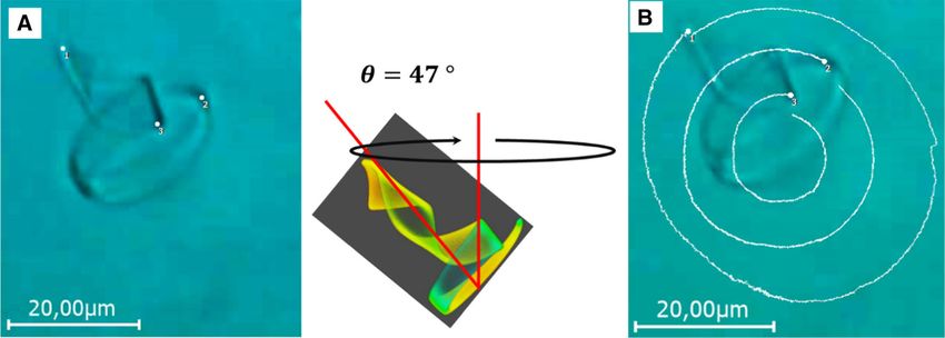
Figure 7a, b and the SI movie 6 show the movement
So far, we have demonstrated the differentiation between of the same conical helix, while it was tilted toward the
a head and a tail of the conical helix and shown that it capillary wall by an angle of 47 ◦ [41]. In this sequence,
can be actuated to undergo directed motion by pulsed the light actuation period was 1.6 ms. Under these
NIR-light. Going a step further, we hypothesize that the conditions, the amplitude is so small that the helix
coupling of different motional modes within one object conformation appears optically unchanged. However, it
can be controlled by the pulse rate and the intensity moved steadily around an imaginary axis with the head
of the NIR-irradiation. As a consequence, we expected oriented inward. Figure 7a shows the tracking points
that the motion can be directed by the choice of the (white dots) to trace the rotation of the helix. The
pulse sequences. In Fig. 4, we depicted the motility at white traces depicted in the overlay image 7B show the
relatively short irradiation pulses (3 ms on/8 ms off). trajectory of these points after a full rotation around
Within the confinement of a flat channel, we observed a the imaginary axis, which lasted about 24 s, taking
fast lateral swimming mode, during which the helix got 15,000 actuation cycles. Due to the different displace-
practically fully extended (Sequence Fig. 4A3–4). Fig- ments during one actuation cycle of the ribbon at the
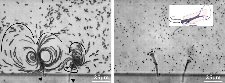
ure 6 and the corresponding movie (Supporting Infor- head and the tail, and the corresponding friction effects
mation SI-movie 5) demonstrates the movement of such on the fluid, a torque is created (on the fluid) causing
a conical helix under irradiation (10 ms on/10 ms off). a clockwise rotation of the helix around its axis.
The helix axial length was 30 µm with a radius of the As mentioned above, the confined situation displayed
spiral at the wider end of 12 µm and 4 µm for the in Figure 6a is characteristic for the 20 ms irradiation
radius of the helix at the narrow end. It is shown in a period at the maximum of the deformation amplitude
situation when it got confined in one direction as the and rate. At short irradiation times, the small deforma-
conical helix oriented perpendicular to the upper wall tion amplitude did not stabilise the spinning of the helix
of the capillary. As already shown in Fig. 4 and the with its axis orthogonal to the surfaces. The orthogo-
corresponding video, this blockade of a forward motion nal orientation is also less stable for longer irradiation
restricts the cone to rotate slowly around its long axis periods. Actually, the 20 ms period coincides with the
while the spiral end and the helix unwind and wind timescale of the diffusion of the water molecules in and
during the heating–cooling cycles. The vertical orienta- out of the gel [42]. Apparently, the orthogonal orienta-
tion enabled us to track the rotation of the extremities tion of the helix is stabilized only because of the actua-
of the cone around its long axis and thus to measure tion (kinematic stability) and that it should be possible
the time dependence of the cone’s radii. The inset in to direct the locomotion by changing the pulse period.
Fig. 6a depicts the view along the axis of the truncated That is indeed possible, as demonstrated in the follow-
coil through the spiral end which is in contact with the ing. Figure 8 presents an example, how the swimming
wall. The main image in Fig. 6a shows a superposition can be directed by the modulation of the irradiation. In
of the cone as it rotates clockwise without changing its Fig. 8a, the time-dependent superposition of the images
position during an actuation cycle of 20 s. The outer of two conical helices is depicted as they were irradiated
radius marks the trajectory of the end of the spiral, by a 2 ms on and 8 ms off sequence. (The time between
while the inner radius marks the trajectory of the eye two images was 300 ms.) At this irradiation, the conical
of the helix. Variation of the sequence of actuating light helix opened only slightly and rotated around its long
pulses effects the amplitude of the opening of the coil. axis, alike those shown in Fig. 6, whereas the time for
When we chose the irradiation frequency in a range so a full rotation lasted 18 s. The image sequence displays
that the cone remained entrapped in its orientation, we different positions of the arc of the spiral as it rotates
could analyze the rate of the rotation around the long in one case clockwise and in the other case counter-
axis of the cone. The variation of the angular velocity clockwise. Whether the conical helix rotates clockwise
for different irradiation sequences is shown in Fig. 6b or counter-clockwise is controlled by the handedness of
(light-on and light-off times were kept identical). The the helix which in turn is determined by small asym-
double-log diagram indicates that the rate of the motion metries in the structure of the wedge shaped ribbon
can be regulated over a range of two orders of magni- [16]. When the irradiation time was increased from 2
tude from roughly one revolution per minute at low to 4 ms, while the cooling time was kept constant at
and high frequencies to more than one revolution per 8 ms, the ribbon unwound to nearly full extension and
12379 Page 8 of 12 Eur. Phys. J. E (2021) 44 :79 Fig. 5 A1–4 sequence of images of the conical helix shown after 67 s indicating that while it spins, it translates and in Fig. 2d, when actuated by 200 µs long NIR-pulses fol- rotates clockwise. Note that the motion is strongly biased lowed by a recovery time of 800 µs. The time between images by the glass surface because, in this case, the capillary was was 1.7 s, which corresponds to 5170 light pulses during only 20 µm high. (The corresponding video is presented in which the helix spins counter-clockwise around the helical the Supporting Information, movie SI 4.) axis and makes one revolution. b Trajectory of the helix Fig. 6 a Overlay of optical micrographs that demonstrates image shows a superposition of the conical helix as it rotates the clockwise rotation of a conical helix with its long axis clockwise. The outer radius marks the trajectory of the head oriented perpendicular to the capillary wall above it when of the conical helix, while the inner radius marks the trajec- it has been actuated by light on and light off sequences tory of the tail. The inset contains a snapshot of the view of 10 + 10 ms. This orientation is kinematically preferred along the axis of the conical helix through the wide end when the actuation is chosen to maximize the amplitude of which is close to the wall. b The variation of the angular the oscillation whereby the rotation velocity is maximum. velocity depending on the irradiation period. c The radius The axial length of the conical helix was 30 µm, and the of the tail Rhelix (or inner radius) as a function of the radius glass capillary was 30 µm high and 300 µm wide. The main of the wider head did not have sufficient time to recover its helical confor- induce directed motility of these micro-objects and how mation. Instead it started to wag like a flagellum, obvi- this motion can be stirred in a remarkable way by the ously combined with a rotation around its long axis. control of the energy input. By the choice of the irradia- The main image in Fig. 8b presents the observation of tion sequence, we could command the agitated ribbons the forward movement of two of such ribbons actuated to rotate around at a place and order them to swim for- in their extended state. We displayed a superposition at ward when the irradiation sequence was switched. Here, different times with a time interval of 396 ms. Clearly, the velocity of the forward motion resulted to 20 µm/s the movie demonstrates the forward swimming of the (1/2 body length/s), which is comparable to the non- extended ribbon with its wider end ahead at a velocity confined swimming of a Euglena [2]. of 20 µm/s. The example shows how the rather unpre- We have mentioned above that swimming of such tentious geometry of the wedge like bilayer ribbon in thermoresponsive hydrogel micro-objects in Newtonian combination with a light actuated shape transformation fluid requires a hysteresis motion cycle, which in turn 123
Eur. Phys. J. E (2021) 44 :79                                                                             Page 9 of 12    79

Fig. 7 a Inclined configuration of the conical helix with respect to the glass surface. b Shows clock-wise rotation path
after 24 s under irradiation with 800 µs pulse and 800 µs recovery time. The rotation velocity was 23 deg/s. The drawing
illustrates the tilt angle

Fig. 8 a Overlay of images with an interval of 300 ms           strobe period of 12 ms (4 ms irradiation and 8 ms recovery),
showing the typical deformation and the trajectories of the     it translate by undulation of the body, in this case overlay
tapered ribbon, while it spins clockwise under an irradiation   images with an interval of 396 ms it helps to show a wavelike
period of 10 ms (2 ms on and 8 ms recovery), b while for a      motion. (See the corresponding movie 7)

Fig. 9 Flow direction and the streamlines pattern of tracer     was attached by its narrow end and the arrows describe
microparticles generated by two tethered tapered ribbons        the direction of the flow, Right: the ribbon was attached
during actuation (4 ms pulse and 12 ms recovery). The           by its wider end and the arrows describe the direction of
triangles indicate where the ends got bound to the poly-        movement. The inset illustrate possible streamline during
dimethylsiloxane wall of the compartment. Left: the ribbon      actuation of a free ribbon (See the corresponding movie 8)

                                                                                                                  123
79 Page 10 of 12 Eur. Phys. J. E (2021) 44 :79
entails shape deformation at non-equilibrium condi- could drive the motion from inside the object by plas-
tions. Such body deformation performs work on its envi- monic heating to which the gels respond by volume
ronment because it causes a circulation of the surround- changes that transform to different bending modes.
ing fluid. We visualized the flow of the surrounding liq- While these bending mechanisms are predefined by the
uid for the swimmer in its forward moving state shown bilayer structure of the ribbons, they are controlled
in Fig. 8b by following the traces of small colloidal par- by the deviation of the actuation from the equilibrium
ticles. This has been possible as we have been able to swelling/shrinking path.
observe the extended swimmer in action, while it was Based on these points, we have been able to design
tethered either with its narrow end or with its wide end a microswimmer that swims forward in the direction of
to a wall and could not move out of the image area. the flapping end. This might appear counterintuitive;
In this case, we did not use a rectangular capillary for however, the forward thrust can only be understood by
the microscopic observation, but watched the ribbons the coupling of this motion with the one of the tail.
in a compartment imprinted in a thin layer of poly- It may be speculated that the flapping head stabilizes
dimethylsiloxane rubber that was sealed by a thin cover the direction of the forward thrust of the tail. A more
glass yielding a square water cavity of (500 × 500) µm2 detailed analysis should be a subject of hydrodynamic
and 30 µm in height. We assume that the ends were modeling. The forward speed was determined up to 6
tethered to the edge of the silicone cavity by hydropho- body length/s, which is comparable to the rates mea-
bic interaction and with the help of the cover glass. sured for bacteria Thiovulum majus [43].
Figure 9 shows two distinct patterns of flow lines It should be noted that the locomotion of our
induced by the periodic deformation of either the widest microswimmer is in fact not fully autonomous, but
part (left) or the narrow tip (right) of the tapered rib- still controlled from the outside, i.e., by the energy
bons which got tethered to the silicone edge by their uptake and thus the width of the irradiation pulses and
opposite ends. For the free ends, we now can see the the delay between them. A fully autonomous swimmer
flow in the surrounding water. The arrows indicate the would require a mechanism such that the swimmer itself
respective flow direction. The flow lines are clearly dis- will control the switching between energy uptake and
tinct and different for the two ends. Hence, they indi- relaxation. This task has not been addressed here. For
cate different modes of motion for the wider and the a light-driven swimmer this might be achieved by orien-
narrower end of the wedge-shaped ribbon. While the tation or temperature-sensitive light absorption. Alter-
wide end of the ribbon undergoes sideways flapping natively, the swimmers could be driven by an intermit-
indicated by the very well-developed vertical vortices, tent chemical reaction. Such a metabolic energy source
the narrow end evidently demonstrates also a rotational remains subject of topical investigations [44,45]. Most
component around the main axis of the ribbon com- chemical transformations are too slow to cause non-
bined with the wagging of the tail. In a first attempt, we equilibrium situations within small open objects when
describe the motion like it is depicted in the scheme in stress generation is diffusion limited [46]. Hence, chemi-
Fig. 9b. How and whether the coupling of theses modes cal non-equilibrium in living organisms is typically con-
of motion, flapping and rotational wagging could cause trolled by membranes and pores [47]. An exception is
the forward motion in the direction of the wider end is given by coupling the oscillatory Belousov–Zhabotinsky
a question beyond the scope of this publication. Cer- (BZ) reaction to the volume change of gels and stress
tainly, the model in Fig. 9b gives a base for advanced generation, whereas the reaction itself is heterogeneous
mathematical modeling of the observed motility of the in space [48], Within a gel beam, the oscillation can
freely swimming ribbon. cause bending deformation [49], transport, and peri-
staltic pumping [50]. This behavior was modelled with
multiphysics simulations of three-dimensional poroelas-
tic systems coupled to the Oregonator model [51–53].
3 Conclusion It has been shown that the propagation of a Belousov–
Zhabotinsky reaction–diffusion front in a submillimeter
Complementary to the quickly advancing understand- gel disk induces local changes in the curvature of the
ing of the swimming of microorganisms, we demon- disk that result in periodic 3D flapping [44]. It will be
strated rather simple design principles for systems interesting how such autonomous and periodic buckling
that can mimic swimming by body shape deformation deformation propagating along the thin body could be
excluding propelling by a rotary motor. Firstly, and combined with the multi-mode design of the swimmers
actually compelling by the laws of thermodynamics, described in this report [54].
the actuation must follow a non-equilibrium path. Sec-
ondly, directional swimming that distinguishes between Supplementary information The online version con-
forward and backward movement does not only require tains supplementary material available at https://doi.org/
a swimmer with a ‘head’ and a ‘tail’ but should also 10.1140/epje/s10189-021-00084-z.
involve coupling of different modes of motion. Thirdly,
coupled modes of motion allow to control and direct Acknowledgements This research was supported by the
the locomotion by the energy input modulation as the German science foundation, through the priority program
different modes can be actuated to different extent. on microswimmers Grant No. 255087333 and by the Euro-
All three points became possible by the fact that we pean Research Council, Jellyclock Grant No. 695716. We
123Eur. Phys. J. E (2021) 44 :79 Page 11 of 12 79
have also benefited from the thriving scientific environment 6. E.M. Purcell, Life at low Reynolds number. Am. J.
provided by the SFB 985 on functional microgels and micro- Phys. 45(1), 3–11 (1977)
gel systems. AM would like to thank especially Hang Zhang 7. D. Alizadehrad, T. Krüger, M. Engstler, H. Stark, Sim-
with whom this project was initiated as well as Eric Lauga ulating the complex cell design of Trypanosoma brucei
and Lyndon Koens for the inspiration on the tapered helix and its motility. PLoS Comput. Biol. 11(1), e1003967
design. (2015)
8. B.M. Friedrich, I.H. Riedel-Kruse, J. Howard, F.
Funding Open Access funding enabled and organized by Julicher, High-precision tracking of sperm swimming
Projekt DEAL. fine structure provides strong test of resistive force the-
ory. J. Exp. Biol. 213(8), 1226–1234 (2010)
Author contribution statement A.M designed the study; 9. T.-W. Su, I. Choi, J. Feng, K. Huang, E. McLeod, A.
A.M and O.J acquired and analysed the data; RV designed Ozcan, Sperm trajectories form Chiral Ribbons. Sci.
irradiation and temperature control set up, AM and MM Rep. 3(1), 1664 (2013)
interpreted the data and wrote the manuscript. R.V, O.J, 10. L. Alvarez, B.M. Friedrich, G. Gompper, U.B. Kaupp,
M.M and A.M critically reviewed the intellectual content of The computational sperm cell. Trends Cell Biol. 24(3),
the manuscript and approved its publication. 198–207 (2014)
11. J.F. Jikeli, L. Alvarez, B.M. Friedrich, L.G. Wilson, R.
Pascal, R. Colin, M. Pichlo, A. Rennhack, C. Brenker,
Open Access This article is licensed under a Creative Com- U.B. Kaupp, Sperm navigation along helical paths in 3D
mons Attribution 4.0 International License, which permits chemoattractant landscapes. Nat. Commun. 6(1), 7985
use, sharing, adaptation, distribution and reproduction in (2015)
any medium or format, as long as you give appropriate credit 12. S. Schuster, T. Krüger, I. Subota, S. Thusek, B.
to the original author(s) and the source, provide a link to Rotureau, A. Beilhack, M. Engstler, Developmental
the Creative Commons licence, and indicate if changes were adaptations of trypanosome motility to the tsetse
made. The images or other third party material in this arti- fly host environments unravel a multifaceted in vivo
cle are included in the article’s Creative Commons licence, microswimmer system. eLife 6, e27656 (2017)
unless indicated otherwise in a credit line to the material. If 13. B. Nasouri, A. Vilfan, R. Golestanian, Minimum dissi-
material is not included in the article’s Creative Commons pation theorem for microswimmers. Phys.l Rev. Lett.
licence and your intended use is not permitted by statu- 126(3), 034503 (2021)
tory regulation or exceeds the permitted use, you will need 14. D. Agostinelli, R. Cerbino, J.C.D. Alamo, A. DeSi-
to obtain permission directly from the copyright holder. mone, S. Höhn, C. Micheletti, G. Noselli, E. Sharon,
To view a copy of this licence, visit http://creativecomm J. Yeomans, D. Agostinelli, R. Cerbino, J.C.D. Alamo,
ons.org/licenses/by/4.0/. A. DeSimone, S. Höhn, C. Micheletti, G. Noselli, E.
Sharon, J. Yeomans, MicroMotility: state of the art,
recent accomplishments and perspectives on the math-
ematical modeling of bio-motility at microscopic scales.
References Math. Eng. 2(2), 230–252 (2020)
15. C. Sybesma, in Microbiorobotics: Biologically Inspired
1. G. Gompper, R.G. Winkler, T. Speck, A. Solon, C. Microscale Robotic Systems. Elsevier: Amsterdam, p.
Nardini, F. Peruani, H. Löwen, R. Golestanian, U.B. 253 (2017)
Kaupp, L. Alvarez, T. Kiørboe, E. Lauga, W.C.K. 16. A. Mourran, H. Zhang, R. Vinokur, M. Möller, Soft
Poon, A. DeSimone, S. Muiños-Landin, A. Fischer, N.A. microrobots employing nonequilibrium actuation via
Söker, F. Cichos, R. Kapral, P. Gaspard, M. Ripoll, F. plasmonic heating. Adv. Mater. 29(2), 1604825 (2017)
Sagues, A. Doostmohammadi, J.M. Yeomans, I.S. Aran- 17. H. Zhang, L. Koens, E. Lauga, A. Mourran, M. Möller,
son, C. Bechinger, H. Stark, C.K. Hemelrijk, F.J. Ned- A light-driven microgel rotor. Small 15(46), 1903379
elec, T. Sarkar, T. Aryaksama, M. Lacroix, G. Duclos, (2019)
V. Yashunsky, P. Silberzan, M. Arroyo, S. Kale, The 18. H. Zhang, A. Mourran, M. Moller, Dynamic switching
2020 motile active matter roadmap. J. Phys. Condens. of helical microgel ribbons. Nano Lett. 17(3), 2010–2014
Matter 32(19), 193001 (2020) (2017)
2. M. Rossi, G. Cicconofri, A. Beran, G. Noselli, A. DeSi- 19. L. Koens, H. Zhang, M. Moeller, A. Mourran, E. Lauga,
mone, Kinematics of flagellar swimming in Euglena gra- The swimming of a deforming helix. Eur. Phys. J. E
cilis : Helical trajectories and flagellar shapes. Proc. 41(10), 119 (2018)
Natl. Acad. Sci. USA 114(50), 13085–13090 (2017) 20. M. Heskins, J.E. Guillet, Solution properties of poly(N-
3. G. Noselli, A. Beran, M. Arroyo, A. DeSimone, isopropylacrylamide). J. Macromol. Sci. Part A Chem.
Swimming Euglena respond to confinement with a 2(8), 1441–1455 (1968)
behavioural change enabling effective crawling. Nat. 21. H. Zhang, in Out of Equilibrium Actuation of Micro-
Phys. 15(5), 496–502 (2019) printed Hydrogel Objects for Ultrasmall Locomotor Sys-
4. E. Lauga, T.R. Powers, The hydrodynamics of swim- tems. RWTH Aachen University (2017)
ming microorganisms. Rep. Prog. Phys. 72(9), 096601 22. J.P. Rolland, R.M. Van Dam, D.A. Schorzman, S.R.
(2009) Quake, J.M. DeSimone, Solvent-resistant photocurable
5. J. Elgeti, R.G. Winkler, G. Gompper, Physics of “liquid teflon” for microfluidic device fabrication. J. Am.
microswimmers-single particle motion and collective Chem. Soc. 126(8), 2322–2323 (2004)
behavior: a review. Rep. Prog. Phys. 78(5), 056601
(2015)
12379 Page 12 of 12 Eur. Phys. J. E (2021) 44 :79
23. S. Timoshenko, Analysis of bi-metal thermostats. J. 41. The tilt angle was calculated from the length of the
Opt. Soc. Am. 11(3), 233–255 (1925) projection of the main axis of the truncated coil
24. S. Bartels, A. Bonito, R.H. Nochetto, Bilayer plates: 42. J.M. Skotheim, L. Mahadevan, Dynamics of poroelastic
model reduction, Γ-convergent finite element approx- filaments. Proc. R. Soc. Lond. Ser. A Math. Phys. Eng.
imation, and discrete gradient flow. Commun. Pure Sci. 460(2047), 1995–2020 (2004)
Appl. Math. 70(3), 547–589 (2017) 43. A.P. Petroff, X.-L. Wu, A. Libchaber, Fast-moving bac-
25. S. Alben, B. Balakrisnan, E. Smela, Edge effects deter- teria self-organize into active two-dimensional crystals
mine the direction of bilayer bending. Nano Lett. 11(6), of rotating cells. Phys. Rev. Lett. 114(15), 158102
2280–2285 (2011) (2015)
26. A. DeSimone, Spontaneous bending of pre-stretched 44. C.M. Pooley, A.C. Balazs, Producing swimmers by
bilayers. Meccanica 53(3), 511–518 (2018) coupling reaction–diffusion equations to a chemically
27. N. Hu, X. Han, S. Huang, H.M. Grover, X. Yu, L.N. responsive material. Phys. Rev. E 76(1), 016308 (2007)
Zhang, I. Trase, J.X.J. Zhang, L. Zhang, L.X. Dong, 45. I. Levin, R. Deegan, E. Sharon, Self-oscillating mem-
Z. Chen, Edge effect of strained bilayer nanofilms for branes: chemomechanical sheets show autonomous peri-
tunable multistability and actuation. Nanoscale 9(9), odic shape transformation. Phys. Rev. Lett. 125(17),
2958–2962 (2017) 178001 (2020)
28. T.V. Kármán, Festigkeitsprobleme im Maschinenbau, in 46. R. Yoshida, M. Tanaka, S. Onodera, T. Yamaguchi,
K. Mechanik, F. Müller, editors, Vieweg+Teubner Ver- E. Kokufuta, In-Phase synchronization of chemical and
lag: Wiesbaden, pp. 311–385 (1907) mechanical oscillations in self-oscillating gels. J. Phys.
29. E. Efrati, E. Sharon, R. Kupferman, Buckling transition Chem. A 104(32), 7549–7555 (2000)
and boundary layer in non-Euclidean plates. Phys. Rev. 47. C. Sybesma, Biological transport processes, in Bio-
E 80(1), 016602 (2009) physics, Springer Netherlands: Dordrecht, pp. 195–211
30. T. Barois, L. Tadrist, C. Quilliet, Y. Forterre, How a (1989)
curved elastic strip opens. Phys. Rev. Lett. 113(21), 48. R. Yoshida, T. Takahashi, T. Yamaguchi, H. Ichijo, Self-
214301 (2014) oscillating gel. J. Am. Chem. Soc. 118(21), 5134–5135
31. M. Liu, L. Domino, D. Vella, Tapered elasticæ as a (1996)
route for axisymmetric morphing structures. Soft Mat- 49. S. Maeda, Y. Hara, T. Sakai, R. Yoshida, S. Hashimoto,
ter 16(33), 7739–7750 (2020) Self-walking gel. Adv. Mater. 19(21), 3480–3484 (2007)
32. T.J. Merkel, K.P. Herlihy, J. Nunes, R.M. Orgel, J.P. 50. S. Maeda, Y. Hara, R. Yoshida, S. Hashimoto, Peri-
Rolland, J.M. DeSimone, Scalable, shape-specific, top- staltic motion of polymer gels. Angew. Chem. Int. Ed.
down fabrication methods for the synthesis of engi- 47(35), 6690–6693 (2008)
neered colloidal particles. Langmuir 26(16), 13086– 51. V.V. Yashin, A.C. Balazs, Pattern formation and
13096 (2010) shape changes in self-oscillating polymer gels. Science
33. S.V. Nikolov, P.D. Yeh, A. Alexeev, Self-propelled 314(5800), 798–801 (2006)
microswimmer actuated by stimuli-sensitive bilayered 52. I.C. Chen, O. Kuksenok, V.V. Yashin, R.M. Moslin,
hydrogel. ACS Macro Lett. 4(1), 84–88 (2015) A.C. Balazs, K.J. Van Vliet, Shape- and size-dependent
34. C. Wischnewski, J. Kierfeld, Snapping elastic disks as patterns in self-oscillating polymer gels. Soft Matter
microswimmers: swimming at low Reynolds numbers by 7(7), 3141 (2011)
shape hysteresis. Soft Matter 16(30), 7088–7102 (2020) 53. P. Dayal, O. Kuksenok, A.C. Balazs, Directing the
35. T. Yamaue, M. Doi, The stress diffusion coupling in the behavior of active, self-oscillating gels with light. Macro-
swelling dynamics of cylindrical gels. J. Chem. Phys. molecules 47(10), 3231–3242 (2014)
122(8), 084703 (2005) 54. P.W. Miller, N. Stoop, J. Dunkel, Geometry of wave
36. A. Suzuki, T. Ishii, Y. Maruyama, Optical switching in propagation on active deformable surfaces. Phys. Rev.
polymer gels. J. Appl. Phys. 80(1), 131–136 (1996) Lett. 120(26), 268001 (2018)
37. J. Wang, D. Gan, L.A. Lyon, M.A. El-Sayed, 55. H. Mary, G.J. Brouhard, Kappa: analysis of curvature in
Temperature-jump investigations of the kinetics of biological image data using B-splines. bioRxiv, 852772
hydrogel nanoparticle volume phase transitions. J. Am. (2019)
Chem. Soc. 123(45), 11284–11289 (2001)
38. H.H. Richardson, M.T. Carlson, P.J. Tandler, P. Her-
nandez, A.O. Govorov, Experimental and theoretical
studies of light-to-heat conversion and collective heat-
ing effects in metal nanoparticle solutions. Nano Lett.
9(3), 1139–1146 (2009)
39. A.O. Govorov, H.H. Richardson, Generating heat with
metal nanoparticles. Nano Today 2(1), 30–38 (2007)
40. G. Baffou, H. Rigneault, Femtosecond-pulsed optical
heating of gold nanoparticles. Phys. Rev. B 84(3),
035415 (2011)
123You can also read