3D AND 4D MODELING FOR DESIGN AND CONSTRUCTION COORDINATION: ISSUES AND LESSONS LEARNED
←
→
Page content transcription
If your browser does not render page correctly, please read the page content below
3D AND 4D MODELING FOR DESIGN AND CONSTRUCTION
COORDINATION: ISSUES AND LESSONS LEARNED
SUBMITTED: September 2006
REVISED: July 2007
PUBLISHED: July 2007 at http://itcon.org/2007/26/
EDITOR: B-C Björk

Sheryl Staub-French, Assistant Professor
Department of Civil Engineering, University of British Columbia
email: ssf@civil.ubc.ca

Atul Khanzode, Business Analyst and PhD Candidate
DPR Construction Inc. and Department of Civil and Environmental Engineering, Stanford University
email: atulk@stanford.edu

SUMMARY: 3D and 4D modeling tools have been available in the marketplace for some time. The past few
years has seen a growing interest from the design and construction community to adopt these tools. As many
project teams are realizing, implementing 3D and 4D modeling on an actual project is a complicated process
that requires a coordinated effort. No guidelines currently exist on using these tools in a multi-disciplinary and
multi-organizational environment and project teams are forced to figure this out on their own in real time as the
project progresses. This paper addresses this shortcoming by providing guidelines that describe how to
overcome the technical, procedural and organizational issues confronted by project teams as they undertake
this new way of working. Specifically, the paper describes different approaches for assembling a project team to
leverage these technologies, the modeling requirements for implementing 3D and 4D projects, the 3D and 4D
modeling processes, the benefits and shortcomings of the process and technologies, the effect of these
technologies on the project's outcome, and the lessons learned. This paper is intended for industry professionals
interested in pursuing this type of innovative project delivery. This paper will also be of interest to researchers
as it illustrates the limitations of emerging 3D and 4D technologies.

KEYWORDS: 3D model, 4D model, computer aided design (CAD), virtual design and construction, virtual
building technologies, design coordination, MEP coordination, construction scheduling.

1. INTRODUCTION
In recent years, we have seen significant improvements in the tools available to model a construction project
using 3D and 4D technologies. Current 3D modeling tools offer pre-defined objects that facilitate the
development, routing, and connection of building systems in 3D, and provide conflict detection mechanisms
that help to automatically identify physical interferences between components. 4D modeling tools link a
project’s scope in 3D with the construction schedule to graphically simulate the construction process. Many
research efforts have discussed the potential of these tools to significantly improve design coordination and
construction execution. However, implementing 3D and 4D modeling on an actual project in a multi-
disciplinary and multi-organizational environment is a complicated process that requires a coordinated effort.
There are a variety of technical, procedural, and organizational issues that must be addressed, which might
explain their limited use. Moreover, there is little research that critiques these tools in the context of project
teamwork on actual projects. Yet, without demonstrating their benefits and providing guidelines for
implementation, it is difficult for practitioners to invest the resources necessary to adopt these technologies.
In practice, 3D and 4D technologies have been applied on a variety of construction projects. Prior research
efforts have compiled detailed case studies that assess the benefits and limitations of these tools and their impact
on project performance (Fischer and Haymaker 2001, Staub-French and Fisher 2001, Kam et al., 2003).
Researchers have also critiqued the functionality of 3D and 4D technologies to meet the needs of industry
(McKinney and Fischer 1998, Songer et al, 1998, Koo and Fischer 2000, Heesom and Mahdjuobi 2004). Some
research efforts have also investigated the application of 3D and 4D modeling tools for specific purposes, such
as constructability analysis (Ganah et al. 2005) and resource management (e.g., Akinci et al. 2003). Other
research studies have documented the benefits and challenges of applying 3D / 4D tools specifically to the

ITcon Vol. 12 (2007), Staub-French and Khanzode, pg. 381
coordination of Mechanical, Electrical, Plumbing, and Fire Protection (MEP/FP) systems on complex projects
(e.g., Khanzode et al., 2005, Staub-French and Fischer 2001). Finally, researchers have also investigated
techniques to enhance the interaction capabilities of 3D and 4D models using immersive technologies (Messner
et al. 2006) and virtual reality (Whyte et al. 2000). These studies clearly demonstrate that 3D/4D technologies
have been well established and can be applied to resolve complex design and construction challenges. Although
much has been written on the application of 3D and 4D technologies, few guidelines exist that outline what is
required for multi-disciplinary project teams to apply these tools in real time on actual construction projects.
This paper provides 3D and 4D modeling guidelines for industry professionals interested in pursuing this type of
innovative project delivery. These guidelines generalize the authors’ unique experience as model developers,
integrators, and coordinators on two different building construction projects, and outline an optimized process
for implementation based on their lessons learned. We discuss the technical, procedural and organizational
issues confronted by project teams as they undertake this new way of working. Specifically, the paper describes
different approaches for assembling a project team to leverage these technologies, the modeling requirements
for implementing 3D and 4D projects, the 3D and 4D modeling processes, the benefits and shortcomings of the
process and technologies, the effect of these technologies on the project's outcome, and the lessons learned. This
paper is intended for industry professionals interested in implementing these technologies on actual projects.
This paper will also be of interest to researchers as it illustrates the limitations of emerging 3D and 4D
technologies and the challenges of using them in practice.
The projects studied demonstrate that although there is room for improvement, current 3D and 4D technologies
provide significant benefits to project teams in developing coordinated and constructible designs and
construction sequences. Specifically, 3D and 4D models help project teams to identify design conflicts, design
errors, sequencing constraints, access issues, fabrication details, and procurement constraints that impact the
efficiency of the project delivery process. We believe that the use of these tools help project teams minimize
risk and attract quality team members to construction projects and will be commonplace in the coming years as
the industry copes with the realities of a tight labor market. We found that these technologies had a dramatic
impact on project execution, including:
        •      the elimination of field interferences,
        •      less rework,
        •      increased productivity,
        •      fewer requests for information,
        •      fewer change orders,
        •      less cost growth, and
        •      a decrease in time from start of construction to facility turnover.
The next sections describe the scope and organization of the projects studied, the 3D and 4D coordination
processes, and the impact of 3D and 4D technologies on the project’s outcome.

2. PROJECT SCOPE AND ORGANIZATION
The authors worked on two different building construction projects that implemented 3D and 4D modeling to
various degrees throughout the design and construction process: (1) Camino Medical Center in Mountain View,
California; and (2) Sequus Pharmacueticals Pilot Plant Facility in Menlo Park, California. The next sections
describe these projects in detail, including the scope, the organization, the modeling responsibilities, and the
authors’ roles on the project.

2.1     The Camino Medical Group Project
The Camino Medical Group project in Mountain View California is a new Medical Office Building facility. The
project scope includes a 250,000 square foot, three-storey Medical Office Building and a two-storey 1,400 space
parking garage. The Medial Office Building includes patient exam rooms, doctor’s offices, surgery and
radiology rooms, public spaces, a cafeteria, numerous conference rooms etc. The project owner, Sutter Health, a
major provider of Healthcare services in Northern California, adopted Virtual Building technologies
(specifically 3D / 4D tools) for the successful delivery of this project. The negotiated contract for this project is
about $100M. Construction started in January 2005 and the project was completed on April 30th, 2007.

ITcon Vol. 12 (2007), Staub-French and Khanzode, pg. 382
FIG. 1: 3D rendering of the three-storey medical office building for the Camino Medical Group Project in
Mountain View, California.

2.1.1     Project Organization
The Architect for this project is Hawley Peterson and Snyder Architecture, the Mechanical Engineer is Capital
Engineering, and the General Contractor is DPR Construction Inc. The owner, along with the Architect,
Engineers and Contractor pre-qualified the MEP and FP subcontractors for their ability to work using the 3D /
4D coordination and collaboration tools. A detailed guideline was created to pre-qualify the subcontractors for
their ability to collaborate using 3D / 4D tools. This guideline included the ability to produce 3D models using
parametric objects, and compatibility of software products with the design review software. The MEP/FP
subcontractors selected for this project include Southland Industries (HVAC), JW McClenahan Company
(Plumbing), Cupertino Electric (Electrical) and North Star Fire Protection (Fire Protection).
2.1.2     Modeling Responsibilities
The Architect was responsible for providing the 3D model for the architectural and structural scope of work.
The subcontractor team used these architectural and structural models to model their scope of work. The
General Contractor was responsible for coordinating the MEP Design process, which included performing clash
detection and resolution using the 3D models, coordinating the installation sequence for the MEP trades, and
producing 4D models. The subcontractors agreed to develop their design using 3D tools under a Design-Assist
method and agreed to complete coordination using 3D / 4D tools.
The MEP Design on this project is unique in the sense that it is being managed using the Lean Project delivery
process. It is not the intent of this paper to explain Lean Construction. For more information, refer to the Lean
Construction Institute website (www.leanconstruction.org). In essence, Lean Construction advocates early
involvement of subcontractors in the design process, the elimination of negative iteration, and pulling the design
from the construction sequence. On the Camino Project, the MEP subcontractors were brought on board in the
Schematic Design phase. They were responsible for assisting the engineers in the Detailed Design phase and
producing a fully coordinated set of 3D MEP models in the Construction Documents phase. Table 1 shows the
modeling responsibilities for the Camino project and the project phase that the model was created. The starting
point for the coordination process was the Architectural and Structural 3D model that was created in the
Schematic Design stage. The subcontractors then took these models and developed the 3D models on their own
in the Design Development stage. The objective of the program was to eliminate negative iteration and reduce
the cycle time by using the 3D models created by the subcontractors to develop a fully coordinated MEP / FP
model that could be used for fabrication and construction.

ITcon Vol. 12 (2007), Staub-French and Khanzode, pg. 383

TABLE 1: Modeling Responsibilities for the Camino Medical Group Project.
Company                    Role                  Modeling Scope               3D Software              Phase Model
                                                                                                       Created/Coordinated

Hawley Peterson and        Architect             Architectural Modeling in    Autodesk Architectural   Schematic Design
Snyder                                           3D                           Desktop (ADT)
KPFF Engineers             Structural            Structural Steel, Concrete   ADT, ETABS               Schematic Design
                           Engineers             Foundation, and Shear
                                                 Walls in 3D
Capital Engineering        Mechanical            Mechanical Systems in        AutoCAD                  Schematic Design
                           Engineers             2D
The Engineering            Electrical            Electrical Systems in 2D     AutoCAD                  Schematic Design
Enterprise                 Engineers
DPR Construction, Inc.     General Contractor    Overall Coordination of      NavisWorks, ADT          Design Development
                                                 MEP in 3D
Southland Industries       Mechanical            Ductwork and Piping in       3D Pipe Designer,        Design Development and
                           Subcontractor         3D                           CADDuct, NavisWorks      Construction Documents
Cupertino Electric         Electrical            Conduit and Cable Trays      3D Pipe Designer,        Design Development and
                           Subcontractor         in 3D                        NavisWorks               Construction Documents
JW McClanahan              Plumbing              Plumbing System in 3D        3D Pipe Designer,        Design Development and
Company                    Subcontractor                                      NavisWorks               Construction Documents
North Star Fire            Fire Protection       Fire Protection System in    FireACAD                 Design Development and
Protection                 Subcontractor         3D                                                    Construction Documents

2.1.3        Author’s Role on the Project
One of the authors, Atul Khanzode, was intimately involved in the MEP coordination process on the Camino
project while working for DPR Construction. The author was a key member of the project team and participated
part time during the MEP coordination process from April of 2005 to December 2005. The author also wrote a
lessons learned report for the team that included the use of 3D tools for MEP coordination and the use of the
Lean Project Delivery System on the project (Khanzode et al. 2005). The author’s role is summarized below
(specific details are provided in subsequent sections):
         •        Helping the team define and setup the technical logistics on the project. The technical logistics
                  involved defining how the servers would be setup to share the models, the file naming conventions
                  for the model files, and how the model files would be integrated in 3D in Navisworks.
         •        Determining the phase schedule for coordination. This involved working with the MEP
                  subcontractors and the architect and engineering (A/E) team to determine an overall schedule for
                  the MEP coordination work.
         •        Determining the handoffs between designers and the subcontractors detailing team. This involved
                  establishing the specific design scope that would be handed off to the subcontractors’ detailers
                  from the A/E team.
         •        Integrating the 3D models created by the subcontractors detailing team. This involved gathering all
                  the model files from the subcontractor’s detailers and then merging these files with the
                  architectural and structural models.
         •        Identifying physical conflicts between models using NavisWorks Clash Detective program. This
                  involved defining the batches for clash detection and selecting the appropriate systems. For
                  example, clashes between HVAC ductwork and steel were determined by defining a batch in
                  NavisWorks and selecting HVAC models to clash against the structural steel model. This was
                  completed for all possible dual combinations of systems on the project.
         •        Publishing reports that identified the specific clashes and documented the action items for each
                  clash that needed to be resolved. These reports were distributed to the project team to
                  communicate the changes needed in each discipline’s 3D models to resolve the issues identified.
         •        Tracking the commitments from subcontractors towards completion of the outstanding issues. This

ITcon Vol. 12 (2007), Staub-French and Khanzode, pg. 384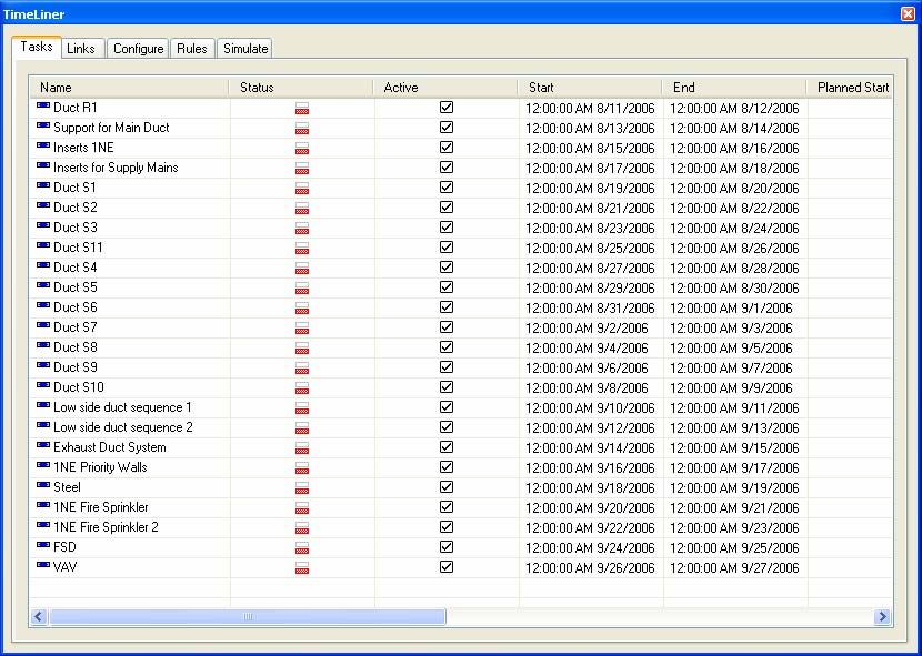
involved using the weekly work planning process where commitments were sought from the
subcontractors and tracked for resolution.
• Creating 4D models based on the weekly work plans created by the subcontractors. This process is
described in detail in section four of this paper.
• Participating in the coordination process to determine the installation sequence for the MEP work.
This process is also described in detail in the context of 4D modeling for the MEP installation
work.
2.2 The Sequus Project
The project’s scope was to construct a pilot plant facility within an existing warehouse for Sequus
Pharmaceuticals, a bio-tech company located in Menlo Park, California. The facility contains 20,000 square feet
of available space, with 3,440 square feet of office space, 3,100 square feet of manufacturing space, 2,900
square feet of process development space, and 4,800 square feet of future expansion space. The MEP systems
were designed such that the majority of the work was placed on an equipment platform. The platform was
necessary because the existing structure was not capable of supporting the increased loads from the MEP
systems and related equipment. Construction started in May 1998 and substantial completion was completed as
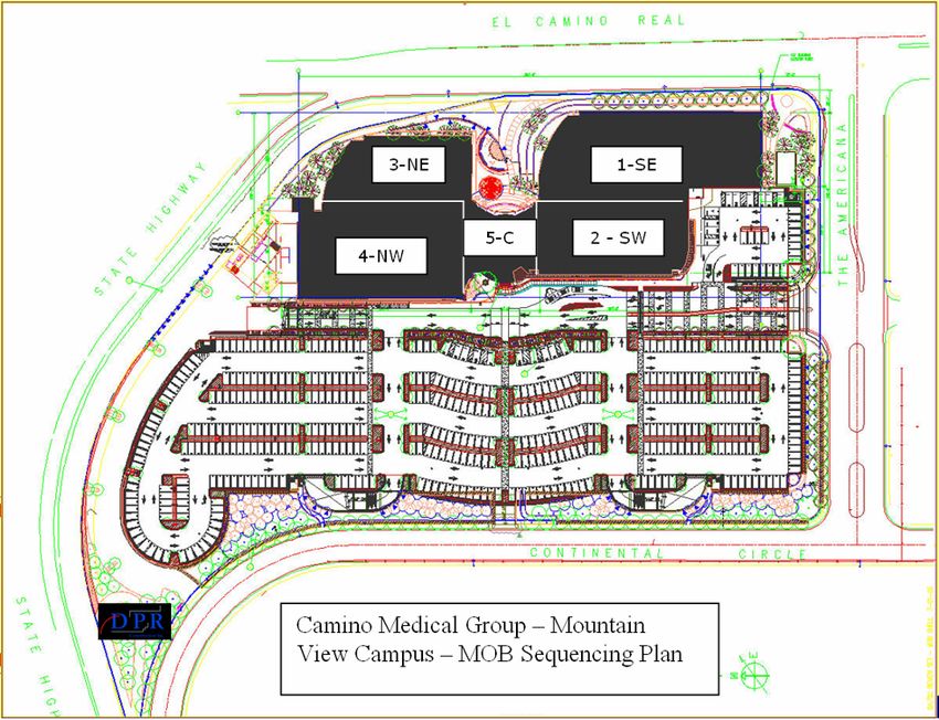
scheduled on February 1, 1999. The negotiated contract price was approximately $6M. Fig. 2 shows the
integrated 3D model.
FIG. 2: Integrated 3D Model of the Sequus Pharmaceuticals Pilot Plant in Menlo Park, California.
2.2.1 Project Organization
The Sequus project was unique in that the general contractor assembled the design-build team prior to design
and construction. The project team consisted of the following companies: the design firm Flad & Associates, the
General Contractor Hathaway Dinwiddie Construction Company (HDCC), the engineering firm Affiliated
Engineers Incorporated, the piping subcontractor Rountree Plumbing & Heating (RPH), the HVAC
subcontractor Paragon Mechanical (PM), and the electrical subcontractor Rosendin Electric Incorporated (REI).
The general contractor selected each member of the design-build team based on their experience using 3D CAD
technology on past construction projects and previous experience working with each other. Each team member
made a commitment to model their respective scope of work in 3D CAD using a design-build approach.
2.2.2 Modeling Responsibilities
In general, the design firm was responsible for managing the design process and creating the 3D model of the
architectural scope of work. The general contractor was responsible for orchestrating and managing the
distribution of electronic design information, design coordination, and managing the construction process. The
engineering firm was responsible for providing the basis of design and schematic drawings for the mechanical,
electrical, and piping work. The MEP subcontractors were responsible for the detailed design and 3D modeling
ITcon Vol. 12 (2007), Staub-French and Khanzode, pg. 385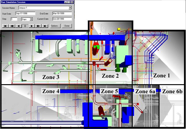
of their scope of work.
Table 2 summarizes the modeling responsibilities for the various project participants. The unique aspect of the
assignment of modeling responsibilities on this project is that the designs are created by the participants who are
responsible for installation and can leverage the designs throughout construction. The engineers created the
Basis of Design and the schematic drawings but the subcontractors did all the 3D modeling for the MEP
systems. This collaborative design approach enabled each company to get feedback quickly on their designs.
Participants were able to communicate directly with the other team members to explain their design intent. Each
team member had an incentive to provide the 3D models and this feedback because they could leverage their
own 3D models and the designs created by others to support their project management functions throughout the
design and construction processes.
TABLE 2: Modeling Responsibilities for the Sequus Project.
Company                    Role                      Modeling Responsibility        3D Software        Phase Model
                                                                                                       Created /Coordinated

Flad and Associates        Architect                 Architectural Modeling in 3D   Archt by           Schematic Design
                                                                                    Autodsys
Affiliated Engineers       Mechanical,               Basis of Design and            N/A                Schematic Design
Incorporated               Electrical, and Process   Schematic Drawings for the
                           Engineers                 MEP Systems
Hathaway Dinwiddie         General Contractor        Overall Coordination of MEP    AutoCAD            Design Development
Construction Co.                                     Design
Rountree Plumbing &        Plumbing                  Mechanical and Process         Multi-pipe by      Design Development and
Heating                    Subcontractor             Piping in 3D, 3D MEP           UHP Process        Construction Documents
                                                     Coordination                   Piping
Paragon Mechanical         Mechanical                Ductwork and Mechanical        Autodesk           Design Development and
                           Subcontractor             Equipment in 3D                Building Systems   Construction Documents
Rosendin Electric          Electrical                Conduit, Cable Trays, and      AutoCAD            Design Development and
                           Subcontractor             Lighting in 3D                                    Construction Documents

2.2.3         Author’s Role on the Project
The first author worked full time for Hathaway Dinwiddie Construction Company during design and
construction of the Sequus Project. A significant part of her responsibilities focused on supporting the 3D design
coordination process, enabling the use of the 3D models for different construction management purposes, and
developing and managing the 4D model. Specifically, she supported the project team with the following
activities:
          •     Worked with project team members to develop design guidelines to aid the electronic 3D design
                coordination process. These guidelines will be discussed in detail in the next section.
          •     Supported the electronic 3D design coordination process. This included integrating the 3D models
                for design coordination meetings, working with the different 3D models to facilitate design
                coordination, and maintaining a digital archive.
          •     Documented the results of the 3D design coordination meetings. This involved documenting the
                conflicts and solutions during the design coordination meetings. In some cases, it also involved the
                preparation of a summary report of the meeting discussion for distribution to other members of the
                team.
          •     Developed custom 2D and 3D models to support the General Contractor’s other project management
                functions. For example, the author prepared dimensioned 2D drawings of the concrete pads for the
                Air Handler Units using the 3D mechanical model.
          •     Identified drawing methods and data manipulation techniques to support design-cost integration of
                the 3D designs. Although not discussed in this paper, we also investigated the feasibility of
                integrating the different 3D models with cost estimating software (Staub-French and Fischer 2001).
          •     Developed and maintained the master construction schedule. This included working with the project
                superintendent, the project manager, and the subcontractors’ foremen to provide summary, detailed,

ITcon Vol. 12 (2007), Staub-French and Khanzode, pg. 386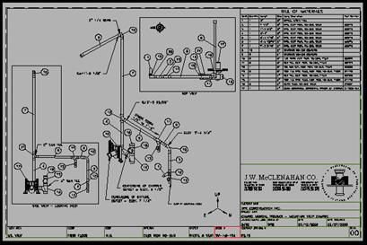
and look-ahead schedules to the various stakeholders.
        •    Created and maintained a 4D model to assist with coordination of day-to-day construction
             operations. This included working with the different subcontractors to represent each discipline’s
             workflow and relevant activities, manipulating the different discipline-specific 3D models to
             facilitate the linking of 3D objects and activities, and updating the schedule and 4D model as the
             design and construction strategy changed and evolved. This will be discussed in detail in section 4.

3. 3D DESIGN COORDINATION
In a complex building project, building system coordination is a critical and challenging task. It involves the
detailed layout and configuration of the various building systems such that it complies with design, construction,
and operations criteria (Barton 1983, Tatum and Korman 2000). Specialty contractors are typically responsible
for the coordination of MEP systems, including responsibility for checking clearances and identifying routes,
fabrication details, and installation locations (Tatum and Korman 2000).

3.1     Current 2D Design Coordination Process
The design coordination process typically begins when the design and preliminary routing of the building
systems are complete. The specialty contractors encounter common constraints that determine the system
routing: the building structure, corridors, shear walls, fire walls, major equipment locations, and architectural
requirements, such as ceiling type and interstitial space (Korman and Tatum 2001). Consequently, each
specialty contractor routes their system to their advantage as they consider these constraints, which is reflected
in the preliminary drawings. This includes minimizing the length of branches and number of fittings, choosing
prime locations for major components, routing close to support points, and designing for most efficient
installation by their own trade (Korman and Tatum 2001). The level of detail in the preliminary drawings often
varies by trade. Typically, the HVAC and piping systems are sized at this stage whereas the electrical and fire
protection are not. Consequently, some of the building systems are drawn to scale while others are drawn simply
as lines with references to component sizes.

FIG. 3: Typical view of MEP systems coordinated in a 2D paper-based process.
Design coordination is an iterative process that starts with the specialty contractors bringing their preliminary
drawings to a coordination meeting. The drawings are typically created in 2D and printed on transparent paper
at 1/4-inch scale. During the coordination meeting, each specialty contractor places their 2D drawing on a light
table to compare the different building system designs. Fig. 3 shows a typical view of MEP systems being
coordinated using a 2D coordination process. The specialty contractors identify conflicts and develop solutions
that are red-lined on the 2D drawings. This process continues until the coordination is complete and the
specialty contractors sign-off on each other's drawings to signify their acceptance.
The current 2D paper-based design coordination is time-consuming, inefficient, and often leads to sub-optimal
project performance as design conflicts are encountered and have to be resolved in the field. Creating and
coordinating the designs in 3D allows project teams to integrate their designs electronically in the computer and
identify conflicts in all three dimensions. Moreover, sharing electronic 3D models enables the project team to

ITcon Vol. 12 (2007), Staub-French and Khanzode, pg. 387
leverage the 3D design information throughout the design and construction process.

3.2     3D Design Coordination Process
Going from 2D to 3D design is a complicated process that requires a significant coordinated effort to fully
leverage the benefits of 3D models. We identified the following ten steps as essential to setting up a 3D design
process. These steps describe the optimal process based on the challenges we encountered:
        1.     Identify the Potential Uses of the 3D Models
        2.     Identify the Modeling Requirements
        3.     Establish the Drawing Protocol
        4.     Establish a Conflict Resolution Process
        5.     Develop a Protocol for Addressing Design Questions
        6.     Develop Discipline-specific 3D Models
        7.     Integrate Discipline-specific 3D Models
        8.     Identify Conflicts between Components/Systems
        9.     Develop Solutions for the Conflicts Identified
        10.    Document Conflicts and Solutions

3.2.1 Step 1: Identify the Potential Uses of the 3D Models
The project team should discuss the potential uses of the 3D models on a given project and identify the specific
uses that will be implemented. For example, the 3D models could be used for thermal simulation, cost
estimating, fabrication, shop drawings, user group visualization, etc. The use of the model often dictates the
modeling requirements in terms of the level of detail and the modeling techniques that must be utilized. For
example, if the architectural model is going to be used for thermal simulation then rooms must be explicitly
modeled. If the model is going to be used for stakeholder visualization, then room details that are often
important to user groups, such as light switches and electrical outlets, may also need to be modeled. If the model
is going to be used for cost estimating, then the components must be modeled in a way that quantities can be
extracted. If the model is to be used for creating fabrication and installation drawings then it also needs to
include the correct objects that could then be pulled into a material requisition sheet and organized into a pre-
fabrication work order (Fig. 4).

FIG. 4: Figure shows a pre-fabrication isometric drawing of a plumbing waste and vent assembly with the Bill
of Materials that was generated automatically from the 3D Model on the Camino Project.

ITcon Vol. 12 (2007), Staub-French and Khanzode, pg. 388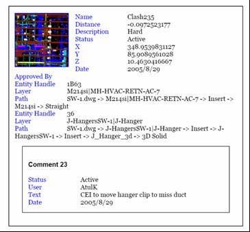
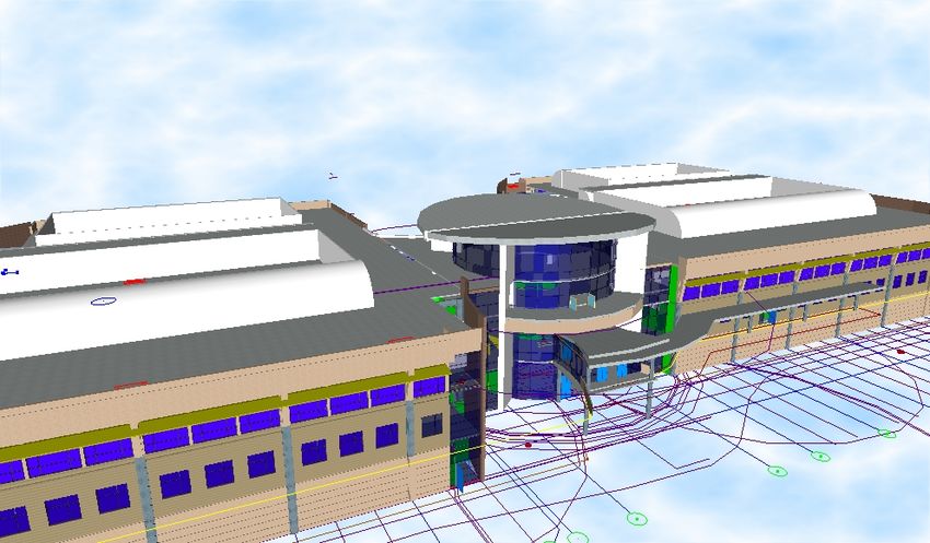
3.2.2 Step 2: Identify the Modeling Requirements
It is essential that the project team identifies who will create the 3D models, when the 3D models will be
created, and how the 3D models will be created. Specifically, this step involves the following:
Identify the modeling responsibilities for the various scopes of work. This involves establishing the
responsible party, and in some cases, the handoff or transition between parties. For example, on the Sequus
Project the engineer was responsible for establishing the basis of design which excluded all CAD modeling,
while the MEP subcontractors were responsible for creating the detailed 3D CAD models. Handoffs between
parties become important if the scope of the 3D modeling efforts is shared by engineers and subcontractors. For
example, on the Camino Project, the Mechanical Engineers modeled the HVAC systems to a certain point in
2D, and then the Mechanical Subcontractor detailed the scope in 3D.
Establish the scope of the 3D modeling effort and the level of detail to be modeled. To address this issue,
project teams should consider the possible uses of the 3D models (step 1), as well as the cost and benefit of
modeling a scope of work in 3D. For example, rebar could be modeled in 3D to facilitate procurement of these
components but the benefits may not justify the expense. In contrast, the Structural Engineer on the Camino
Project did not model the gusset plates in 3D, but these elements were critical for 3D coordination and should
have been included.
Establish the work breakdown structure. It is important to identify how the models are going to be integrated
and create a breakdown structure that is consistent and agreed upon by all parties. For example, on the Camino
Project, the Medical Office Building was divided into 12 distinct quadrants, and the models were developed for
each quadrant and coordinated by each quadrant.
Create a schedule that identifies key modeling activities. The schedule should specify when the models will
be created, coordinated (conflicts identified), updated (conflicts resolved), and approved (ready for fabrication).
Ideally, these milestones should be incorporated into the construction schedule and coordinated with related
activities for installation.

FIG. 5: Flow chart of design coordination process established on the Camino Project.
Fig. 5 shows a flow chart that illustrates the formal process established on the Camino Project for coordination
and collaboration between designers, subcontractors, and the general contractor. The MEP coordination process
was driven by the construction process. For example, MEP coordination was done by quadrant to meet with the
schedule of installing inserts before the deck slab was poured, in a sense pulling design based on the
construction sequence. Negative iteration in design was avoided by starting the modeling process early, and
sharing incomplete designs early and often. The subcontractors also were encouraged to work directly with the

ITcon Vol. 12 (2007), Staub-French and Khanzode, pg. 389
designers to get answers to questions quickly rather than going through the traditional RFI workflow between
subcontractor – general contractor – designer and back. An online system to make and keep track of all
commitments was used as a substitute for the RFI process. This system called Commitment Manager acted as a
conduit between the team and supported the Design process using 3D / 4D models efficiently.
3.2.3 Step 3: Establish the Drawing Protocol
To ensure that the 3D models can be electronically integrated and coordinated, the project team should establish
a protocol that specifies the drawing conventions that will be implemented by all the parties.
Project Reference Point (0,0,0): The project team must employ the same reference point so that the models
integrate appropriately in all three dimensions. This is extremely important for 3D coordination otherwise the
team will spend a lot of time trying to combine the models together for conflict detection purposes. For the
Sequus and Camino Projects, the reference point was established by the design team, which was dictated by the
architectural 3D model.
File Naming Convention: The file name should communicate the company that created the 3D model, the
scope of the 3D model, and the version of the 3D model. On the Camino Project, we followed the AIA File
Naming Convention but appended the initials of the subcontractor to the drawing. For example, the file name
“M211A_SI.dwg” communicates the following: M = Mechanical, 2 = HVAC, 1 = 1st Floor, 1 = 1st Quadrant,
A = Area, and SI = Southland Industries. However, this convention was not optimal for 3D coordination using
Navisworks Clash Detective, therefore, we recommend that the company name be represented first in the file
name if this software is being used.
Version Control: The version of the file can be represented in the file name by appending the file name with
the date, or it can be handled separately through the use of folder names on FTP sites or collaboration sites.
Layering Convention: A layering convention should be established to facilitate 3D coordination. Any Object
that requires separate coordination should be on a separate layer so that it can be viewed independently and
easily turned on and off, which may include: text or annotations, structural grids, different systems (e.g., supply
and return systems, junction boxes), flexible systems that can be easily routed (e.g., flex duct), and connections
(e.g., sprinkler mains vs. heads).
Color Scheme: The color scheme should facilitate visual communication of the different scopes of work. Fig. 6
shows the color scheme established on the Camino Project, which shows the colors used for different systems
and companies.

FIG. 6: Color Scheme used on the Camino Project for 3D coordination.

3.2.4 Step 4: Establish a Conflict Resolution Process
Setting up a process for identifying and resolving conflicts is extremely important to ensure that the team is

ITcon Vol. 12 (2007), Staub-French and Khanzode, pg. 390
making continuous progress towards a conflict-free solution on the project. In order to do this, there needs to be
a system to detect conflicts between trades, document the conflict and the responsible party, and then resolve the
conflict in the same sequence.
Identify the specific design review software that will be used during the 3D design coordination process.
The software can be a CAD package (e.g., Autodesk Building Systems), or specific 3D coordination software
(e.g., Navisworks Clash Detective). Although both packages facilitate the detection of physical interferences, we
found that Navisworks Clash Detective was far superior in detecting some soft conflicts (e.g., interferences
between physical components and clearance spaces), managing the process of detecting and resolving conflicts
(e.g., conflicts can be tracked according to their status - new, active, approved, resolved, and old), and
documenting the conflicts identified (e.g., conflict reports can be generated). Fig. 7 shows a snapshot of the
Navisworks model for the Camino Project and the nine clash tests that were created to facilitate conflict
detection between the systems.
Establish the process for sharing drawing files. We recommend that project teams use a formal collaboration
website rather than an FTP site. In addition, we recommend that such a system facilitate both informal and
formal information sharing. For example, the different disciplines should be able to pull the most recent model
from the website when developing their 3D models, which doesn’t require a formal coordination meeting.

FIG. 7: Screenshot from the combined MEP/FP model for one of the quadrants from the Camino project and
the 9 clash tests that were created.
Establish the timing and general meeting process for coordinating the 3D models. This should include the
timing of meetings, timing of 3D model uploads, organizations involved, drawings to be coordinated, objects
included (e.g., no text, no flex duct, no xrefs, specific systems, etc.), and systems to be coordinated (e.g.,

ITcon Vol. 12 (2007), Staub-French and Khanzode, pg. 391
structural and HVAC).
Identify a responsible party to facilitate the electronic design coordination process. The responsible party
downloads and electronically integrates the 3D drawings that are scheduled to be coordinated in the meeting.
This typically includes drawings for the architectural, structural, piping, ductwork, lighting, and fire protection
systems. The party responsible for this activity can vary but the key issue is making sure someone is
responsible. On the Camino Project this was the responsibility of the General Contractor while on the Sequus
Project this responsibility was given to the Mechanical Contractor.
3.2.5 Step 5: Develop a Protocol for Addressing Design Questions
This step is necessary if the contractors are responsible for developing the 3D models. We have learned that
there needs to be a very clear and unambiguous mechanism in place for subcontractors and detailers who are
working on developing the models to ask questions to the design team and resolve issues quickly as they come
up, particularly on fast-track projects. We realized that the normal RFI process is inadequate when using the 3D
models due to the unnecessary lag time for resolving issues. On the Camino Project, we adopted a web-based
system called Commitment Manager, which the team members used to ask questions of each other (Fig. 8). We
also agreed that during the Design Phase, the subcontractors and detailers should be able to pose a question
directly to the most appropriate member of the design team rather than route it through the General Contractor
in the form of an RFI so that valuable time is saved in resolving the issue.

FIG. 8: Screenshot of the Commitment Manager Action Cycle being used for making requests and answering
questions on the Camino Project.

3.2.6 Step 6: Develop Discipline-specific 3D Models
Each discipline creates their respective 3D model using the discipline-specific design software used in their
firm. Typically, the architect creates the architectural model first and then the other members of the team use the
architectural model as the background when creating their 3D designs. Then, after the first coordination
meeting, all members of the team can share and use each other’s 3D models as a background. In this process,
designs are being optimized from a coordination and constructability perspective as they are being developed.
Therefore, coordination and constructability is not simply assessed at a specific point in time during design
development, it is considered throughout the design development process.
3.2.7 Step 7: Integrate Discipline-specific 3D Models
The responsible party downloads and integrates the 3D models in preparation for the coordination meeting. On
the Camino project, the project team used Navisworks to coordinate the building systems in 3D. The 3D models

ITcon Vol. 12 (2007), Staub-French and Khanzode, pg. 392
created using Quick Pen and CADDuct were combined into a single model in Navisworks and then the
Navisworks Clash Detective module was used to define clash tests and identify clashes.
3.2.8 Step 8: Identify Conflicts between Components/Systems
A substantial amount of time in coordination meetings is spent trying to identify and resolve design conflicts.
They are looking for "hard" conflicts, which are physical interferences between components, as well as “soft”
conflicts, which are interferences between design components and access spaces or violations of clearances.
Hard conflicts can be identified manually or automatically depending on the particular software being utilized.
Fig. 9a shows a meeting between the General contractor and the Mechanical and Fire Protection contractors
identifying all the conflicts between the Mechanical and Fire Protection systems for one of the quadrants of the
building. Fig. 9 shows a hard conflict that was automatically identified between the Fire Sprinkler Pipe and the
Supply Duct.

FIG. 9a: Formal coordination and conflict identification     FIG. 9b: Hard conflict between the Fire Sprinkler Pipe
meeting between the General Contractor and the               and the Supply Duct that was automatically identified in
Mechanical and Fire Protection contractors on the            Navisworks Clash Detective on the Camino Project.
Camino Project.
On the Sequus Project, the team focused on certain areas and building systems and identified conflicts manually.
For example, in one meeting, the detailer and foreman for Rountree Plumbing met with the detailer for Paragon
Mechanical to coordinate the piping and ductwork connections around the air handler units with the 3D models
in the computer (Fig. 10a). Although this process enabled the team to identify most conflicts, it would have been
more efficient to identify such conflicts automatically.

                                                               Design Solution

    Design Conflict           15"                                                       9"

FIG. 10a: Design of connection to Air Handler Unit and       FIG. 10b: Revised conflict-free design of connection to
conflict identified on the Sequus Project.                   the Air Handler Unit that was developed on the Sequus
                                                             Project.

3.2.9 Step 9: Identify Solutions for the Conflicts Identified
After conflicts were identified, the team jointly develops a solution that works for all parties involved. Fig. 10b
shows the solution to the design conflict at the air handler connection shown in Fig. 10a which was encountered

ITcon Vol. 12 (2007), Staub-French and Khanzode, pg. 393
on the Sequus Project. This design solution called for raising the air handler connection by 6" to avoid the
piping. This design solution was detected early in the design coordination process and the AHU manufacturer
implemented the change at no additional cost.
3.2.10 Step 10: Document Conflicts and Solutions
It is important to document the conflicts addressed in the coordination meetings including, the design conflict (a
snapshot or clash report from Navisworks), the proposed solution, the responsible party, the systems that were
coordinated, the drawing files used (for version control), the meeting date, and the organizations/people
involved in the coordination process. On the Camino project we used the Navisworks software to create a
conflict identification and resolution report that listed a particular conflict and how it was to be resolved by the
next iteration (Fig. 11). This document was used to identify and resolve the clashes. The report was generated
directly out of Navisworks.
FIG. 11: Conflict identification and resolution report from the Camino Project generated directly from
Navisworks Clash Detective.
3.3 Benefits
The following summarizes the key benefits of designing and coordinating building systems in 3D, and when
possible, gives an example of each benefit realized on one of the projects.
• Most design conflicts are identified prior to construction: By modeling in 3D and
electronically integrating the 3D models, design coordination and constructability analysis is
performed with a more accurate representation of the building systems. On the Camino and Sequus
projects, this process is further enhanced because the participants with the construction expertise
that had the most to benefit from the models were actually designing and coordinating the 3D
models. Moreover, many conflicts are avoided because the different disciplines are using each
other’s 3D models as they design.
• Productivity is significantly improved: Most design conflicts are identified and resolved prior to
construction enabling a more efficient and productive installation process. In addition, many of the
mechanical systems can be fabricated directly from the 3D model in the shop, which can lead to
significant productivity gains. On the Sequus Project, the mechanical contractor used the 3D
models extensively for field coordination and daily planning of construction activities, resulting in
a substantial increase in field productivity. As stated by the Project Manager: "Field productivity
was improved. Even on a system where we did not attempt to do any prefab, the installers were
able to refer to small area isometric drawings to facilitate installation." On the Camino Project, the
productivity for the mechanical subcontractor was significantly improved. They estimate
approximately 25-30% improvement in productivity compared to their estimated productivity for
installation of duct and piping scopes of work on traditional projects (Fig. 12).
ITcon Vol. 12 (2007), Staub-French and Khanzode, pg. 394Field Productivity Over Estimate
35%
Improvement Over Baseline
30%
25%
20%
15%
10%
5%
0%
Jan Feb Mar April
Project Timeline
Rectangular Duct Round Duct Shaft Duct HHW Pipe
FIG. 12: Comparison of field productivity versus estimated productivity for the Camino project for installation
of ductwork and heating hot water pipe (courtesy of Southland Industries, 2006).
• Less Rework: The MEP design coordination process eliminates most of the design conflicts prior
to construction. Typically, many conflicts go undetected until they are encountered during
installation, often resulting in expensive rework. On the Sequus Project, the only rework that was
required occurred between trades that did not model their scope of work in 3D. In fact, the
superintendent for the general contractor noted the "seamless" installation process for the 3D work.
On the Camino project, after 250,000 square feet had been constructed, there was not a single field
conflict during the installation of the MEP / FP work. According to the Superintendent, he has
never experienced this level of accuracy of field installation before in his 35 years of experience
and estimates that he is spending much less time resolving field issues compared to past projects.
He estimates that on past projects he used to spend 2 to 3 hours per day dealing with these issues,
and on Camino he has spent a total of 10-15 hours over an eight month period after the MEP
installation began.
• Increased opportunity for Pre-fabrication: We believe that modeling and coordinating the MEP
/ FP systems in 3D provides a better opportunity to pre-fabricate materials in a shop environment.
For example on the Camino Project, all of the plumbing systems (piping for water, waste and vent)
were pre-fabricated. Normally the piping is cut in the field. All the low pressure duct system was
also pre-fabricated. Normally only the medium pressure duct is pre-fabricated and the low pressure
smaller duct runs are field assembled. On the Sequus Project, the Mechanical Contractor was able
to fabricate many of the different pipe runs from the 3D models, resulting in time and cost savings
and fewer errors. This was particularly useful for the extremely expensive piping that is used in
Sequus' manufacturing processes. For example, stainless steel pipe can cost approximately
$400/LF in cramped spaces, such as mechanical rooms, and $125/LF in open spaces, such as
laboratories, according to the project manager for Rountree Plumbing. If one measurement is off in
such complicated piping systems, it could cost approximately $700 to fix each mistake. In
addition, the large 4” and 6” piping around the chillers was labor-intensive to install and expensive
to cut. The 3D models allowed Rountree Plumbing to have the supplier fabricate the pipe in the
shop at about 1/3 of the cost. The project manager for Rountree Plumbing stated that "virtually
everything prefabricated from the 3D model was installed as planned."
• Fewer Requests for Information (RFI): There are primarily two reasons why there can be
significantly fewer RFI's on 3D projects: 1) the designs are coordinated and conflicts are identified
early in the construction process (as described above), and 2) the MEP subcontractors are
responsible for the detailed design of their scope of work. By creating detailed 3D models in the
design phase, the MEP subcontractors are able to work out how the components would fit together
and how the building systems would interface. In a traditional process, these issues would often be
ITcon Vol. 12 (2007), Staub-French and Khanzode, pg. 395resolved through the RFI process. On the Sequus Project, there were 60% fewer Requests for
Information (RFI) than expected for a project of this complexity. On the Camino project, out of
233 RFI’s, 160 were confirming RFI’s, about 10% related to the MEP / FP coordination work
where the 3D models were used for coordination, and only two were related to field conflict
issues..
• Fewer Change Orders: Rework is often a big cause for the many change orders that typically
originate during construction. On both the Sequus and Camino projects, there were significantly
fewer change orders than expected for such complex projects. On the Sequus Project, there was
only one contractor-initiated change order for the scope of work modeled in 3D, which is
remarkable for work of this complexity. On the Camino Project, there were zero change orders
related to field conflicts after the construction of MEP systems for the first six quadrants.
• Design errors can be identified prior to construction: On the Sequus project, we identified a
design error that could have potentially caused substantial rework. An AEC chiller was incorrectly
designed in 3D at about 20% its actual size. When this mistake was corrected, the chiller no longer
fit in the space allocated requiring the piping to be re-routed to a new location. This conflict was
resolved three months before the chiller was scheduled for installation.
• Ability to build the system with a less skilled labor force: We believe that modeling and
coordinating the MEP / FP systems in 3D provides an opportunity to create more of an IKEA type
assembly rather than trying to interpret complex drawings to build a system. On the Camino
Project, this has allowed the team to use a less skilled labor workforce to bolt together systems
which would normally require experienced plumbers. For tight labor markets like California, less
skilled labor is often required and it is imperative that tools like 3D / 4D be used to maintain the
quality of installation.
• Improved Safety Performance: A fully coordinated model facilitates a smoother workflow by
helping teams to identify their work area requirements and plan logistics resulting in a much safer
jobsite. On the Camino Project, there was only one recordable injury after 178,000 person-hours.
• Better cost control: On the Camino Project, the MEP / FP subs have adjusted their cost
downwards in finalizing their contracts due to the increased productivity that has resulted from a
highly accurate bill of materials and increased pre-fabrication on the project. We believe that this
has resulted in a much better cost control for the subs performing the work on the project. On the
Sequus Project, cost control was a key concern for the owner. Typical cost growth on projects of
this complexity range from 2% - 10%, with 2% considered extremely successful, according to the
Sequus project manager. The cost growth on the Sequus Project averaged 1% for the MEP
subcontractors, which was mostly due to owner initiated design changes.
3.4 Lessons Learned
On each of these projects, the project team learned many valuable lessons that were critical to the success of the
integrated 3D approach that should be incorporated on future projects. These lessons learned are summarized
below:
• Project teams should determine the stage in the design development process when a specific scope
of work should be modeled in 3D. The sequencing and timing of the design development process
needs to coincide with the design coordination process, the procurement process, and the
construction process, particularly in design-build environments. On the Camino Project, we
learned that the structure should be modeled in 3D before the 3D coordination for MEP trades can
start, and that the HVAC duct needs to be 75% complete before the other trades can really be
productive in routing their utilities as the duct is the most constraining. In addition, one other
lesson learned from Camino is that for multi-storey buildings it is extremely important that the
gravity system be decided very early in the project, otherwise changes to higher floors impact the
design of lower floors.
• Project managers and executives committing to a team-oriented approach should carefully
assemble their project staff. It is critical that each discipline's project team understands the goals of
the project, the level of information sharing needed, and the level of 3D modeling required.
• Assemble teams so that the designs are created by the participants who have the construction
expertise to create constructable designs, and who are responsible for installation and can leverage
the designs throughout construction. A collaborative design approach also provides incentives for
ITcon Vol. 12 (2007), Staub-French and Khanzode, pg. 396team members to provide feedback on the other discipline's designs because they can leverage the
designs created by others to support their project management functions. We recommend pre-
qualifying all the team members for their capability to produce 3D drawings and work in 3D.
• When setting up a 3D project, it is preferable to have one person or one company that is
responsible for the electronic design coordination meetings. Ideally, the company responsible for
the 3D coordination meetings will also be responsible for MEP coordination in general. On the
Sequus Project, however, the mechanical contractor was responsible for electronically integrating
the 3D drawings that were scheduled to be coordinated in the meeting while the General
Contractor was responsible for the MEP coordination process, which led to inconsistencies in the
management of this process.
• Every essential trade on the project should put their design (scope of work) into the 3D model to
leverage the benefits of electronic 3D design coordination. On the Sequus Project, the structural
work was only partially modeled in 3D and the fire sprinkler work was not modeled at all in 3D,
resulting in the only design conflict problems during construction.
• Project teams modeling in 3D require increased design and coordination time. Although this is
offset by benefits in construction, it does need to be addressed in each discipline's estimate and
contract. On the Sequus Project, the mechanical trades reported a 30% increase in design time.
• It is important that all team members agree on a coordination and conflict resolution process.
There needs to be a formal process in place for addressing the conflicts and issues identified in the
3D MEP coordination process. On the Camino Project, we learned that when using Navisworks
Clash Detective it is best to proceed with clash detection in a sequence otherwise fixing one clash
has the potential to generate other clashes. Also, it is important to keep track of who is fixing what
using the Clash Report. Also, defining a process that can guarantee reduced latency to answer
design questions raised by the subs during the modeling process is key to success and allows the
subs to keep working on their models.
• Most of the professionals involved, from the designers and consultants to the subcontractors and
trades and foremen, are used to communicating and understanding a 2D presentation of the design.
To facilitate acceptance and understanding of the 3D models, project teams should provide both
2D and 3D representations when adopting this type of process.
• Issues and conflicts identified in an MEP coordination meeting need to be documented in a way
that facilitates ease of use and interpretation. The 3D model alone does not provide this type of
documentation. There needs to be a complementary document that provides the necessary
annotations and labeling to convey the issues identified and their resolution.
4. CONSTRUCTION COORDINATION
This section describes the current practice of creating and maintaining construction schedules and contrasts it
with the 4D process used on the Sequus and Camino projects. We describe the specific steps required to create
4D models, the issues that must be addressed to ensure successful implementation, and the benefits and
limitations of 4D technologies.
4.1 Current Practice
A major task for construction planners is to determine the sequence of construction activities so that resources
are allocated appropriately and coordination of sub-trades is optimized. Current project management practice
uses CPM (Critical Path Method) schedules to represent the completion of a facility design over time. CPM
schedules show the dependencies between activities, but they do not provide a link between the three
dimensions of space and the fourth dimension of time. Yet the interdependency between this information is
critical for planning, evaluating, monitoring, and coordinating the construction process.
Most construction managers, through years of experience, are able to visualize the construction process in their
heads. Communicating that conceptualization of the construction process, however, is ineffective with
traditional CPM networks and bar charts, resulting in differing perceptions about how the work will actually be
installed in the field. Consequently, many problems go undetected resulting in reactive project management and
sub-optimal project performance as problems get resolved during construction. To proactively manage the
construction process, project teams need to be able to visualize the four dimensional nature of the construction
process.
ITcon Vol. 12 (2007), Staub-French and Khanzode, pg. 397You can also read