RHINO TO STL - BEST PRACTICES - WHITE PAPER AUTHOR VERONICA DE LA ROSA
←
→
Page content transcription
If your browser does not render page correctly, please read the page content below
WHITE PAPER

RHINO TO STL — BEST PRACTICES
AUTHOR VERONICA DE LA ROSA
RHINO TO STL — BEST PRACTICES
INTRODUCTION

                                                                                                                                    Best Practices and Procedures for Getting Quality Prints Out of Your RHINO Models | F001 2015
          In order to get the best quality 3D prints from RHINO CAD models it is important to be
          familiar with the parameters that effect STL file creation. It is essential to adjust these
          parameters before converting your geometries because STL files cannot be modified or
          made smoother. The primary factors that affect the quality of your 3D printed parts during
          modeling and STL creation are:

                           • WALL THICKNESS
                           • MESH SETTINGS
                           • MULTIPLE SHELLS // NESTED PARTS

WALL THICKNESS
          Wall thicknesses can be a major contributor to 3D printing errors. Thin walls in your CAD
          models can make for very fragile and delicate parts that can result in tears and holes during
          support material removal. On occasion, files can not be processed by the printers if the wall
          thicknesses are too thin.

          Use the chart below to ensure wall thicknesses meet minimum requirements.

          MINIMUM FEATURE SIZE
                        POLYJET                                                                                     RAPID TOOLING
                                          SELECTIVE LASER    FUSED DEPOSITION      CAST URETHANES
                                                                                                    CNC MACHINING     INJECTION
                                           SINTERING (SLS)    MODELING (FDM)           (POLYS)
             FLEXIBLE             RIGID                                                                                MOLDING

             0.045 in         0.025 in    0.030 – 0.040 in   0.025 – 0.040 in         0.025 in        0.025 in        0.025 in
                                                                ** Dependant on
                                                                 geometry & size

MESH SETTINGS
          RHINO describes geometry as NURBS surfaces, so files need to be converted as an STL to
          be processed by 3D printers. During this process, RHINO surfaces are translated into
          triangulated meshes approximating the NURBS geometry.

          In general, the finer the resolution of your mesh, the larger the file size and the closer it will
          approximate your RHINO surface. Excessive faceting should be avoided though, as it
          creates larger files that can cause delays in processing and model upload. Super low
          faceting should also be avoided because it results in flat spots where models should be
          curved. The best option is to find a resolution that is detailed enough to build your model
          features accurately while keeping file size manageable.

                                                                                                                                                               1
  3d printer sales // rapid prototyping // design consultation // studiofathom.com // 510.281.9000 // oakland, ca & seattle, wa
MESH SETTINGS IN RHINO
Within RHINO’s mesh Detailed Controls there are seven numerical settings and three check
boxes. Each of these settings will affect the resolution of the mesh and some will work
together. The combined effects of these settings are complex so expect some trial and
Best Practices and Procedures for Getting Quality Prints Out of Your RHINO Models | F001 2015
error. In the meantime, we will discuss the most important setting; max distance edge to
surface. Reference RHINO’s Help section for a detailed description of the other settings.
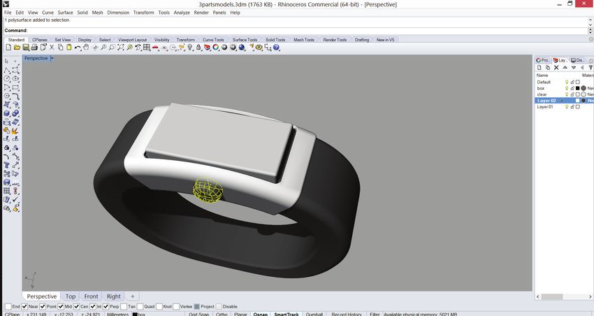
MAX DISTANCE EDGE TO SURFACE
This setting controls how much polygons divide until the distance from a polygon edge
midpoint to the NURBS surface is smaller than the setting’s value. The smaller the value the
more polygons divide to better approximate the NURBS surfaces which also creates for
larger file sizes. Below are examples of surfaces that have been meshed with different Max
Distance Edge to Surface values. Note the correlating file sizes in figure 2.1.
Fig. 2.1 The higher the resolution of your mesh, the larger the file size. It is good practice to turn your NURBS into
meshes within your rhino file and view them in Flat Shade mode (_FlatShade command). This mode shades models
so individual mesh faces are visible (This creates a good preview as to what your part will look like once printed).
2
3d printer sales // rapid prototyping // design consultation // studiofathom.com // 510.281.9000 // oakland, ca & seattle, waBest Practices and Procedures for Getting Quality Prints Out of Your RHINO Models | F001 2015
Fig. 2.2 It is good practice to turn your NURBS into meshes within your rhino file and view them in Flat Shade mode
(_FlatShade command). This mode shades models so individual mesh faces are visible and gives you a preview of
what your part will look like.
To accommodate different 3D printer technologies the Maximum Distance Edge to Surface
values should be less than half a printer’s resolution. For example a setting of 0.01mm is a
good value for a printer with a resolution of 0.03mm.
CREATING A MESH FROM YOUR NURB SURFACES
1. Select the surfaces you want to mesh
2. Enter into the command line _Mesh
3. In the Polygon Mesh Options click on Detailed Controls
4. In the Detailed Option dialogue enter the following settings:
• Maximum angle: 20
• Maximum edge length: 6
• Minimum edge length: 0.0001
• Maximum distance, edge to surface: 0.001 (< 1/2 printer resolution)
EXPORTING THE MESHES IN YOUR RHINO MODEL TO STL
Once the file has been meshed and you are satisfied with its resolution, export the file.
1. Select the mesh
2. Enter into the command line _Export
3. Give the file a name and select STL from the file type menu
4. Hit Save
5. From the STL Export Options select Binary for File (this produces smaller files
than selecting Ascii) — click okay
3
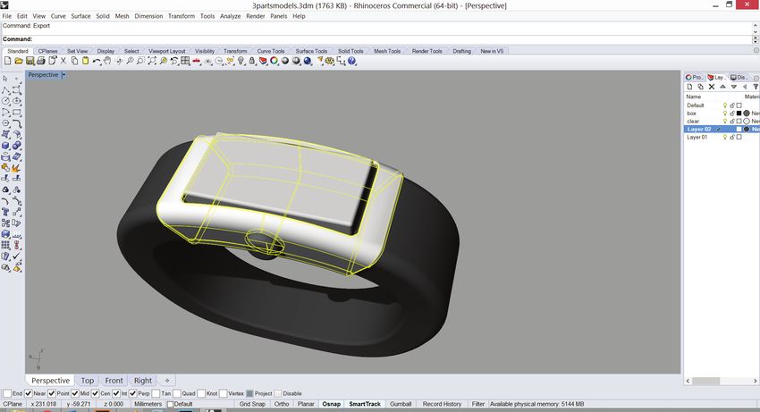
3d printer sales // rapid prototyping // design consultation // studiofathom.com // 510.281.9000 // oakland, ca & seattle, waMULTIPLE SHELLS AND NESTED PARTS
If your model is an assembly and is composed of multiple shells or nested parts you will
need to export each shell individually creating as many STL file as there are parts in the
model. Make sure that you are exporting each shell so that all STLs share the same
Best Practices and Procedures for Getting Quality Prints Out of Your RHINO Models | F001 2015
coordinates. This way when each file is imported into the 3D printing software it will fall into
its relative position within the assembly.
Fig. 3.1 This model contains nested parts that will be printed in different materials. All shells that are of the same
material are selected and exported as one STL. In the case above the outer housing will be printed in VeroWhite,
while the knob will be printed in Tango Black. Items are selected in their relative position so that when imported into
the 3d printing software, they drop into place with the same coordinates.
4
3d printer sales // rapid prototyping // design consultation // studiofathom.com // 510.281.9000 // oakland, ca & seattle, waYou can also read