Deformation Transfer for Triangle Meshes
←
→
Page content transcription
If your browser does not render page correctly, please read the page content below
To appear in SIGGRAPH 2004.

                                Deformation Transfer for Triangle Meshes
                                             Robert W. Sumner                   Jovan Popović
                                       Computer Science and Artificial Intelligence Laboratory
                                              Massachusetts Institute of Technology
         Reference
Source
Target

                                                                                                  Output

Figure 1: Deformation transfer copies the deformations exhibited by a source mesh onto a different target mesh. In this example, deformations
of the reference horse mesh are transfered to the reference camel, generating seven new camel poses. Both gross skeletal changes as well as
more subtle skin deformations are successfully reproduced.

Abstract                                                                   1    Introduction
Deformation transfer applies the deformation exhibited by a source         Mesh deformation plays a central role in computer modeling and
triangle mesh onto a different target triangle mesh. Our approach          animation. Artists hand-sculpt facial expressions and stylized body
is general and does not require the source and target to share the         shapes. They assemble procedural deformations and may use com-
same number of vertices or triangles, or to have identical connec-         plex musculature simulations to deform a character’s skin. Despite
tivity. The user builds a correspondence map between the triangles         the tremendous amount of artistry, skill, and time dedicated to craft-
of the source and those of the target by specifying a small set of         ing deformations, there are few techniques to help with reuse. In
vertex markers. Deformation transfer computes the set of trans-            order to reuse a deformation created for one shape to deform an-
formations induced by the deformation of the source mesh, maps             other, the specific parameters that control the deformation must be
the transformations through the correspondence from the source to          adapted to the new shape. In many cases, adapting these parameters
the target, and solves an optimization problem to consistently ap-         is just as time consuming as starting from scratch. Although spe-
ply the transformations to the target shape. The resulting system          cial purpose adaption methods exist, the problem is compounded
of linear equations can be factored once, after which transferring a       in the common case where many different deformation techniques
new deformation to the target mesh requires only a backsubstitu-           are used in tandem. An automatic adaption method designed for
tion step. Global properties such as foot placement can be achieved        one type of deformation may fail in the presence of others. Fur-
by constraining vertex positions. We demonstrate our method by             thermore, any hand-sculpted alterations will be lost. As a result,
retargeting full body key poses, applying scanned facial deforma-          the work spent designing a deformation typically cannot be reused
tions onto a digital character, and remapping rigid and non-rigid          after its planned application.
animation sequences from one mesh onto another.                                Our research amends this problem by automatically copying de-
                                                                           formations from one mesh onto another. This deformation transfer
CR Categories: I.3.5 [Computer Graphics]: Computational Ge-
                                                                           technique is our central research contribution. We use a general
ometry and Object Modeling—Hierarchy and geometric transfor-
                                                                           approach that requires no knowledge of the actual method used to
mations; I.3.7 [Computer Graphics]: Three-Dimensional Graphics
                                                                           deform the original shape. Our technique is purely mesh-based and
and Realism—Animation
                                                                           does not require the two meshes to share the same number of ver-
Keywords: Deformations, Correspondence, Animation                          tices or triangles, or to have identical connectivity. However, our
                                                                           algorithm is designed for the case where there is a clear seman-
Authors’ contact:                                                          tic correspondence between the two meshes indicating which parts
The Stata Center, 32 Vassar Street, Cambridge, MA 02139                    of the source and target should deform similarly. Our system can
sumner@csail.mit.edu                                                       transfer hand-sculpted alterations as well as deformations resulting
jovan@csail.mit.edu                                                        from arbitrarily complex procedural or simulation based methods.
                                                                           Figure 1 demonstrates our method used to transfer full body defor-
                                                                           mations of a horse mesh onto a camel. The camel mesh was never
                                                                           articulated and the resulting camel deformations are completely de-
                                                                           rived from the source mesh using deformation transfer.
                                                                               With the aid of a correspondence tool, the user supplies a map-
                                                                           ping between the triangles of the source and those of the target. For
                                                                           each triangle of the source mesh, our method computes an affine
                                                                           transformation that takes the triangle from its original position to
                                                                           its deformed position. These affine transformations, together with
                                                                           the correspondence, specify the ideal change in orientation, scale,

                                                                       1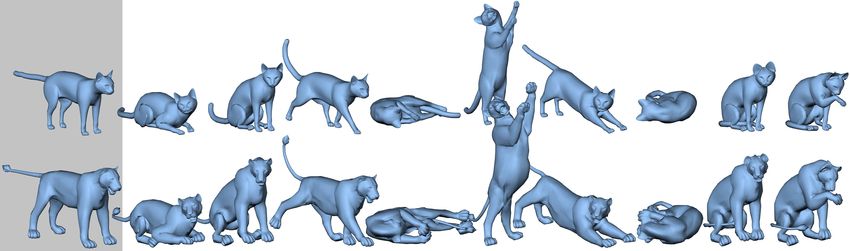
To appear in SIGGRAPH 2004.

and skew of each triangle of the target shape. However, these ideal          as single-weight enveloping or skeleton-subspace deformation de-
transformations will not, in general, be consistent with respect to          forms mesh vertices by blending deformations of nearby skeleton
one another: applied directly without modification, the transfor-            bones. New target meshes can be swapped in by binding their ver-
mations would not preserve the connectedness of the target mesh.             tices to the appropriate bones and setting the desired vertex weights.
Therefore, to find the deformed target shape, deformation trans-             Furthermore, the motion of the skeleton can be parameterized by
fer solves an optimization problem such that the ideal changes are           joint angles to define a set of natural control parameters for direct
matched as closely as possible while maintaining consistency. The            animation of the mesh with keyframing, or for retargeting motion
retargeting process is numerically efficient, as the system of lin-          from a skeleton of a different size and proportion [Gleicher 1998].
ear equations for a source/target pair can be factored and stored in         Deformation transfer is the first step toward the development of
a precomputation step. Transferring a new deformation from the               similar techniques for the animation of meshes with non-skeletal
source to the target requires only performing backsubstitution with          deformations or without an obvious skeletal structure. It general-
the stored factorization. Global properties such as foot placement           izes the binding concept, which maps the motion of mesh vertices
can be achieved using positional vertex constraints.                         to the motion of a skeleton, by mapping deformations of the target
                                                                             mesh to deformations of the source.
                                                                                Deformation transfer can have an immediate impact on example-
2    Background                                                              based techniques, which currently rely on the artist to specify exam-
                                                                             ple shapes. Pose-space deformation, for example, corrects the “col-
Deformation transfer is a generalization of the concept introduced           lapsing elbow” and other problems associated with simple skeleton-
by expression cloning, which transfers facial expressions from one           driven deformations by enabling the artist to sculpt corrective de-
face mesh to another [Noh and Neumann 2001]. In this approach,               formations [Lewis et al. 2000]. Once these corrections have been
each expression is encoded with vertex displacements that define             sculpted, deformation transfer can reduce the effort required to
the differences between the reference face and the expression face.          adapt them to new meshes. Bregler et al.’s cartoon-capture tech-
Expression cloning uses heuristics designed to adapt the direction           nique encodes a motion in the coefficients of a linear combination
and scale of displacement vectors to account for faces of differing          of meshes, which describe the animated character in a selection of
shape and proportions. This representation and adaptation tech-              key poses [2002]. Mapping these motions onto a different character
nique is specialized for the deformations that arise in facial expres-       requires an artist to recreate the new character in every single pose.
sions. Our method transfers arbitrary nonlinear deformations by              Deformation transfer requires only one pose for the new charac-
computing an optimal global deformation of the target shape.                 ter and automates the reproduction of the remaining poses. If the
    One way to represent such a global deformation is with a free-           entire configuration space of the character is described in this man-
form deformation [Sederberg and Parry 1986] in which a lattice of            ner [Ngo et al. 2000; Sloan et al. 2001], deformation transfer could
control points induces a deformation on the enclosed space. With             lead to a technique for mapping the articulation from one character
this or a similar representation, any target mesh can be deformed            to another.
with ease by applying the global deformation to every mesh ver-
tex. The Inkwell 2D system uses precisely this strategy to animate
different 2D characters with the same set of hand-animated Coons             3    Deformation Transfer
patches [Litwinowicz 1991]. However, this approach is harder to
generalize when the source deformation is not initially described            The goal of deformation transfer is to transfer the change in shape
by a free-form deformation or a similar representation. In these             exhibited by the source deformation onto the target. We represent
cases, the method must infer both the structure of the control lattice       the source deformation as a collection of affine transformations tab-
and the position of its control points, or, less optimally, solve for        ulated for each triangle of the source mesh. We use this represen-
the control points of a specific lattice structure [Hsu et al. 1992].        tation because the non-translational portion of each affine transfor-
A fixed lattice structure is not optimal, because a reasonably sized         mation encodes the change in orientation, scale, and skew induced
lattice cannot express arbitrary nonlinear deformations of vertices          by the deformation on the triangle. However, the three vertices of
for every target mesh [Singh and Fiume 1998].                                a triangle before and after deformation do not fully determine the
    Deformation transfer resolves this problem by using locally              affine transformation since they do not establish how the space per-
specified deformations [Barr 1984], which can define any global              pendicular to the triangle deforms. To resolve this issue, we add a
nonlinear deformation of mesh vertices. This approach extends the            fourth vertex in the direction perpendicular to the triangle. Let vi
ideas from Alexa, Cohen-Or, and Levin’s [2000] shape interpola-              and ṽi , i ∈ 1 . . . 3, be the undeformed and deformed vertices of the
tion technique which maximizes the rigidity of a blended shape by            triangle, respectively. We compute a fourth undeformed vertex as
computing the optimal deformation of its interior. We show that
                                                                                 v4 = v1 + (v2 − v1 ) × (v3 − v1 )/ |(v2 − v1 ) × (v3 − v1 )| (1)
                                                                                                                      p
the interior of the target mesh need not be considered for transfer
of mesh deformation. Our boundary formulation has tremendous                 and perform an analogous computation for ṽ4 . We scale the cross-
practical advantages. It greatly simplifies the numerical complexity         product by the reciprocal of the square root of its length since
of the transfer process and makes it easier to specify regions that          this causes the perpendicular direction to scale proportional to the
should move similarly.                                                       length of the triangle edges.
    The concept of deformation transfer can be posed as an anal-                An affine transformation defined by the 3 × 3 matrix Q and dis-
ogy: given a pair of source meshes, S and S 0 , and a target mesh T ,        placement vector d, which, for notational convenience, we write as
generate a new mesh T 0 such that the relationship between T and             Q + d, transforms these four vertices as follows:
T 0 is analogous to the relationship between S and S 0 . This form of
reasoning was used to transfer drawing styles between two curves                                  Qvi + d = ṽi ,    i ∈ 1 . . . 4.             (2)
[Hertzmann et al. 2002]. Deformation transfer applies in the spe-
cific case where the relationship between S and S 0 is a continuous          If we subtract the first equation from the others to eliminate d and
global deformation of the space and not an arbitrary relationship.           rewrite them in matrix form treating the vectors as columns, we get
This specialization enables optimal reproduction of the source de-           QV = Ṽ where
formation on the target mesh. Furthermore, deformation transfer
does not require a common parameterization of the source and tar-                              V = [v2 − v1 v3 − v1 v4 − v1 ]
get meshes. Instead, it employs source and target meshes with                                                                        .          (3)
                                                                                               Ṽ = [ṽ2 − ṽ1 ṽ3 − ṽ1 ṽ4 − ṽ1 ]
matching reference poses much like facial animation uses a neu-
tral face or skeleton-based techniques use a mesh in the T-pose.             A closed form expression for Q is given by
    When the deformation of a triangle mesh is purely skeleton-
driven, transfer is more straightforward. A simple technique known                                        Q = ṼV−1 .                           (4)

                                                                         2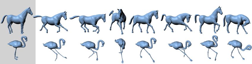
To appear in SIGGRAPH 2004.

Source
Target   Reference

                                                                       A                                   B                                            C

Figure 2: We encode a source deformation with an affine transformation for each source triangle and relate the transformations to the target
through a user supplied triangle correspondence. (A) Using only the non-translational component of the source transformations transfers the
change in orientation and scale to the target triangles but does not position them appropriately relative to their neighbors. (B) Using the source
displacements gives a disconnected shape since consistency requirements are not enforced. (C) Deformation transfer solves a constrained
optimization problem for a new set of target transformations that are as close as possible to the source transformations while enforcing the
consistency requirements: shared vertices must be transformed to the same place.

   We use Equation 4 to compute the source transformations
S1 , . . . , S|S| that encode the change in shape induced by the defor-                                             ...                                      ~
                                                                                                                                                             v   k ∈p(v)
mation, where S refers to the set of triangle indices for the source                            j ∈p(v)             v       Tj v+dj = Tk v+dk = ~v
mesh.                                                                                                                                                              j ∈p(v)
                                                                                                       k ∈p(v)                                         ...
   In order to relate the source deformation to the target mesh with
the set of triangle indices T , the user supplies a mapping M between
the set indices for the source and target triangles:
                                                                                       Figure 3: In order to maintain consistency, the affine transforma-
                                                                                       tions for all triangles j, k ∈ p(v) that share vertex v must transform
                M = {(s1 ,t1 ), (s2 ,t2 ), . . . , (s|M| ,t|M| )}.           (5)       v to the same position.

A pair (si ,ti ) indicates that the target triangle with index ti should
deform like the source triangle with index si . This mapping allows                    affine transformations:
transferred deformations to originate from any region of the source
mesh. There are no restrictions on M. In most cases, it is a general                                                      |M|
                                                                                                                                              2
many-to-many mapping, but it can also be bijective (one-to-one and
onto), surjective (onto), or not-onto. This generality enables trans-
                                                                                                   min
                                                                                           T1 +d1 ...T|T | +d|T |
                                                                                                                          ∑     Ss j − Tt j   F                                (7)
                                                                                                                          j=1
fer between meshes of different tessellations.
                                                                                                  subject to            T j vi + d j = T k vi + dk ,    ∀i, ∀ j, k ∈ p(vi ).
   Our strategy is to transfer the source transformations via the cor-
respondence map to the target. The non-translational portion S of
a source affine transformation S + d encodes the change in triangle                    The matrix norm || · ||F is the Frobenius norm, or the square root of
shape induced by the source deformation. However, we cannot ap-                        the sum of the squared matrix elements.
ply S directly to the corresponding target triangle since S encodes                       A solution of this optimization problem defines a continuous de-
only the change in orientation and size and not the positioning of                     formation of the target mesh up to a global translation. The global
the triangle relative to its neighbors (Figure 2 A). Furthermore, we                   translation can be defined explicitly by setting the displacement di
cannot use the source displacement vectors to resolve this problem                     for any target triangle. In addition, other positional constraints such
since their lengths depend on the size and position of the source                      as foot placement can also be added.
shape. Doing so yields a discontinuous shape (Figure 2 B) and ex-
poses the fact that our deformation representation affords too many
degrees of freedom. It allows the triangles to be transformed arbi-                    4        Vertex Formulation
trarily even though neighboring triangles share vertices.
                                                                                       Although the formulation of deformation transfer in Equation 7 can
   In order to ensure that the affine transformations, when applied                    be solved with quadratic programming techniques, a more efficient
to the target mesh, are consistent with respect to one another, we                     method eliminates the constraints by reformulating the problem in
require that shared vertices be transformed to the same place (Fig-                    terms of vertex positions. The key idea is to define the unknown tar-
ure 3). For the set of target affine transformations T1 + d1 . . . T|T | +             get transformations in terms of the triangles’ vertices. Then, rather
d|T | this requirement is                                                              than solving for the entries of the affine transformations, we solve
                                                                                       directly for the deformed vertex positions. This method satisfies
             T j vi + d j = T k vi + dk ,     ∀i, ∀ j, k ∈ p(vi ),           (6)       all constraints because, by construction, any shared vertex will be
                                                                                       transformed to the same location.
                                                                                          For each target triangle, we add a fourth undeformed vertex
where p(vi ) is the set of all triangles that share vertex vi .                        (Equation 1) and write the non-translational portion of the affine
   In order to transfer the source deformation onto the target mesh                    transformation in terms of the undeformed and deformed vertices
while maintaining these consistency requirements (Figure 2 C),                         T = ṼV−1 . The elements of V−1 depend on the known, unde-
deformation transfer minimizes the difference between the non-                         formed vertices of the target shape. The elements of Ṽ are the co-
translational components of the source and target transformations                      ordinates of the unknown deformed vertices. Thus, the elements of
and enforces the consistency constraints in Equation 6 by solv-                        T are linear combinations of the coordinates of the unknown de-
ing the following constrained optimization problem for the target                      formed vertices.

                                                                                   3
To appear in SIGGRAPH 2004.

    Given this definition, we rewrite the minimization problem as
                                       |M|
                                                                2
                        min
                       ṽ1 ...ṽn
                                       ∑          Ss j − Tt j   F
                                                                  .                   (8)
                                       j=1

Since the target transformations are defined in terms of the un-                                      A                        B                      C                       D
known deformed target vertices, the minimization is over the ver-
tices themselves and the continuity constraints are implicitly satis-
fied. Positional vertex constraints can be enforced by simply treat-                            Figure 4: The correspondence algorithm deforms the source mesh
ing a vertex as a constant rather than as a free variable.                                      into the target, controlled by user selected marker points shown in
   The solution to this optimization problem is the solution to a                               yellow. (A) Target mesh. (B) Source mesh. (C) Source mesh after
system of linear equations. Rewriting the problem in matrix form                                the first phase of deformation where the closest valid point term
yields                                                                                          is ignored. (D) Final deformed mesh using all three terms of the
                          min ||c − Ax̃||22                       (9)                           objective function.
                              ṽ1 ...ṽn
where x̃ is a vector of the unknown deformed vertex locations, c is
a vector containing entries from the source transformations, and A                              Here, T1 , . . . , T|T | are defined in terms of the target vertices accord-
is a large, sparse matrix that relates x̃ to c. Setting the gradient of                         ing to Equation 4, and adj(i) is the set of triangles adjacent to tri-
the objective function to zero gives the familiar normal equations:                             angle i. Note that this term is minimized when the change in defor-
                                    AT Ax̃ = AT c                                    (10)       mation, and not the mesh itself, is smooth. For example, regardless
                                                                                                of the smoothness of the mesh, any rigid transformation applied to
The entries in A depend only on the target mesh’s undeformed ver-                               all triangles is a valid minimum for ES .
tex locations. Furthermore, the system is separable in the spatial                                 Deformation identity, EI , is minimized when all transformations
dimension of the vertices. Thus, for each source/target pair, we                                are equal to the identity matrix:
compute and store the LU factorization of AT A only once. Retar-
                                                                                                                                               |T |
geting any source deformation onto the target mesh only requires
performing backsubstitution to solve separately for the x, y, and z                                                      EI (v1 . . . vn ) =   ∑ ||Ti − I||2F .                   (12)
components of the deformed target vertices. For efficiency, we use                                                                             i=1
a sparse LU solver [Davis 2003]. Since the columns of A corre-                                  The purpose of this term is to prevent the deformation smoothness
spond to the unknown deformed target vertices, and since we add                                 term from generating a drastic change in the shape of the mesh in
an extra vertex for each triangle, the number of columns of A (and                              order to achieve optimal smoothness.
hence the number rows and columns of AT A) is equal to the number                                  The closest valid point term, EC , indicates that the position of
of vertices plus the number of triangles of the target mesh. Table 1                            each vertex of the source mesh should be equal to the closest valid
lists the vertex and triangle counts for the meshes in this paper, and                          point on the target mesh.
Table 2 lists the factorization and average backsubstitution times.
                                                                                                                                                           n
                                                                                                                   EC (v1 . . . vn , c1 . . . cn ) =      ∑ ||vi − ci ||2 ,       (13)
5     Correspondence                                                                                                                                      i=1

                                                                                                where ci is the closest valid point on the source mesh to target vertex
The correspondence between the source and target triangles defines                              i. When computing the closest valid point, vertex normals of the
how the deformation of the source mesh should be transferred to                                 source mesh are compared with triangle normals of the target mesh
the target. We aid the creation of this mapping with a tool that auto-                          and a difference in orientation of less than 90◦ indicates a valid
matically computes the triangle correspondence from a small set of                              point. A grid-based spatial sorting algorithm accelerates the closest
m user selected marker points. Our correspondence technique is an                               point computation.
iterated closest point algorithm with regularization, aided by user                                To compute the deformed vertices ṽ1 . . . ṽn of the source mesh,
selected marker points, that deforms the source mesh into the target                            we define the following minimization problem
mesh. Then, it computes the triangle correspondence by search-
ing for pairs of source and target triangles whose centroids are in                                   min         E(v1 . . . vn , c1 . . . cn ) = wS ES + wI EI + wC EC
close proximity. Figure 4 illustrates this process. Our correspon-                                   ṽ1 ...ṽn                                                                   (14)
dence system is similar to the template fitting procedure described                                                subject to      ṽsk = mk ,            k ∈ 1...m
by Allen, Curless, and Popović [2003] but developed in the context
of our numerical framework.                                                                     where wS , wI , and wC are weights, sk is the source vertex index for
   The correspondence system solves a minimization problem sim-                                 marker k, and mk is the position of marker k on the target mesh. We
ilar to the one we use for deformation transfer, but the objective                              solve this minimization in two phases. In the first phase, we ignore
function is designed to deform one mesh into the other, rather than                             the closet point term by using weights wS = 1.0, wI = 0.001, and
deforming it like the other deforms. The user controls the deforma-                             wC = 0. We solve the problem for the deformed source mesh (Fig-
tion by supplying a set of marker points specified as pairs of source                           ure 4 B). The marker points of the deformed mesh will match ex-
and target vertex indices. Each pair indicates that the source ver-                             actly since they are specified as constraints, and the rest of the mesh
tex, after deformation, should match the location of the target ver-                            will be carried along by the smoothness and identity terms. We use
tex. These markers are enforced as constraints in the minimization.                             this initial estimation to compute a set of valid closest points. Then,
The objective function contains a term that enforces deformation                                in the second phase, we solve the same problem increasing wC each
smoothness, one that prevents over smoothing, and one that moves                                time and updating the closest points after each iteration. Preserving
the source vertices to the target mesh.                                                         wS = 1.0 and wI = 0.001 while increasing wC in four steps from
   Deformation smoothness, ES , indicates that the transformations                              1.0 to 5000.0 produced good results in our tests. Each time the
for adjacent triangles should be equal. For a mesh with n vertices,                             minimization problem is solved, the source mesh is deformed from
we let T be the set of triangle indices and T1 + d1 . . . T|T | + d|T | be                      its original undeformed state. Since wC increases, the source mesh
                                                                                                more closely approximates the target mesh after each iteration (Fig-
the affine transformations that define the deformation. Then,                                   ure 4 C).
                                           |T |                                                     Once the source mesh has been deformed to match the shape of
               ES (v1 . . . vn ) =         ∑ ∑            ||Ti − T j ||2F .          (11)       the target mesh, we compute the triangle correspondences by com-
                                                                                                paring the centroids of the deformed source and target triangles.
                                           i=1 j∈adj(i)

                                                                                            4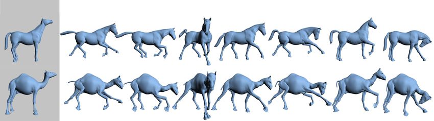
To appear in SIGGRAPH 2004.
Mesh Vertices Triangles
Horse 8,431 16,843 Example Number of LU Factor- Back-
Camel 21,887 43,814 Markers ization substitution
Cat 7,200 14,410 Horse/Camel 65 1.559s 0.293s
Lion 5,000 9,996 Cat/Lion 77 0.299s 0.057s
Face 29,299 58,836 Face/Head 42 1.252s 0.298s
Head 15,941 31,620 Horse/Flamingo 73 1.495s 0.406s
Flamingo 26,907 52,895
Table 2: The number of correspondence markers used and the tim-
Table 1: Number of vertices and triangles for our example meshes. ing results for our examples on a 3.0GHz Pentium IV machine.
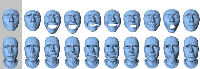
Two triangles are compatible if their centroids are within a certain captured and adapted to the target head. This type of transfer might
threshold of each other and the angle between their normals is less be used when a digital stand-in must replace a real actor, or to map
than 90◦ . This compatibility test prevents two nearby triangles with the facial expressions of a voice actor onto an animated character.
disparate orientation (e.g., triangles from the upper and lower lips Since the scanned data is in the form of face masks and the target
of a face) from entering the correspondence. For each triangle of mesh consists of an entire head and neck, the mapping between the
the deformed source, we compute the closest compatible triangle source and target triangles is not onto. Only a subset of the target
(if any) of the target mesh and add the pair to the correspondence triangles (those of the front of the face) are listed in the correspon-
list. Likewise, for each triangle of the target, we compute the clos- dence. We specify that the deformation of the remaining target tri-
est compatible triangle of the deformed source mesh and add that angles should be minimal by mapping them to the identity matrix.
pair. This process ensures that all triangles of the source and tar- Our deformation transfer technique was designed for the case
get meshes, subject to the compatibility restriction, will be listed where there is a clear semantic correspondence between the source
among the correspondences. A target triangle may correspond to and target. We chose anatomically similar meshes to demonstrate
many source triangles, and vice versa. This feature allows our de- our results since they have an obvious mapping (i.e., leg to leg, head
formation transfer method to accommodate meshes with differing to head, etc.). In Figure 8, we challenge this assumption by transfer-
numbers of vertices and triangles. ring the horse deformation onto a flamingo mesh. The correspon-
dence is ambiguous as the flamingo has only two legs, no tail, and a
beak. We mapped the flamingo’s legs to the horse’s front two legs,
6 Results the flamingo’s body to the entire horse’s body including its tail, and
its beak to the horse’s head. Building this mapping pushes the lim-
Figure 1 shows deformations of a horse transfered onto a camel. its of our correspondence system as the flamingo’s “S”-shaped neck
The reference horse mesh, shown in the gray box, is deformed into must be unbent to match the horse’s straight neck. The deformation
seven key poses. The key poses include obvious skeletal deforma- smoothness term (Equation 11) fights against these large local de-
tions such as bending of the legs or neck as well as more subtle skin formations, requiring the user to select many marker points along
deformations like stretching near the joints. The input to our algo- the neck. However, once the correspondence has been adequately
rithm is the reference horse mesh, the seven deformed horse poses, specified, the flamingo faithfully deforms like the horse. Of course,
the reference camel mesh, and the correspondence between the two a real flamingo’s hips bend in the opposite direction of a horse’s
reference meshes. Given this data, deformation transfer generates front hips, which demonstrates a reason why deformation transfer
seven new camel poses by transferring the source deformations onto between anatomically different meshes may not be appropriate.
the reference camel. Both the gross skeletal changes as well as None of the source and target meshes in our examples share the
the more subtle skin deformations are faithfully reproduced on the same number of vertices, triangles, or connectivity. Table 1 lists
camel. Figure 5 demonstrates a similar set of deformations. Here, this geometric information about each model, and Table 2 gives
key poses of a cat are retargeted onto a lion. Since deformation timing results for each example. Our method is extremely fast.
transfer copies the change in shape induced by the deformation, we For example, the camel mesh, consisting of 21, 887 vertices and
require the source and target reference meshes to have the same 43, 814 triangles, required only 1.559 seconds for factorization and
kinematic pose when skeletal deformations are retargeted. 0.293 seconds on average to solve for each retargeted pose. The
While the deformations of Figures 1 and 5 are primarily skeletal user time required to add the markers and compute the correspon-
in nature, Figure 6 demonstrates the effectiveness of our approach dence for each example was under one hour.
with non-rigid deformations. Here, the horse collapses as if it were
made of a rubber sheet. Its legs buckle and its entire body falls to
the ground, folding on top of itself. The deformations are transfered 7 Conclusion
to the camel, and its body buckles and collapses similarly.
In the accompanying video, we use deformation transfer to re- Deformation transfer is a general mesh based technique that trans-
target two deformations that vary continuously through time. First, fers deformations exhibited by a source mesh onto a different target
we transfer a gallop gait from the horse to the camel, and then mesh. The technique transfers between meshes with different mesh
we transfer the collapsing motion from Figure 6. In order to re- structure (number of vertices, number of triangles, and connectiv-
solve the global positioning of the camel over time and to enforce ity). The process is numerically efficient. A precomputation step
foot/ground contact, we extracted the positions of one vertex on factors and stores the system of equations for a source/target pair.
each foot of the horse over time, performed an overall scaling to Transferring a new deformation involves a backsubstitution with
better match the larger size of the camel, and added vertex con- the factored system.
straints to match a vertex on each camel foot to these positions. The user controls the transfer process by supplying a mapping
Deformation transfer then copies the horse deformation onto the between the triangles of the source and the triangles of the target
camel while simultaneously satisfying the vertex constraints. Be- that identifies which parts should move similarly. Our correspon-
cause computing the source deformations as well as mapping them dence tool assists the user by automatically computing the triangle
to the target are both linear operations, temporal consistency of the correspondence from a small number of user supplied markers.
source animation and vertex constraints results in a temporally co- In order to perform deformation transfer, the source and target
herent target animation. deformations are represented as affine transformations. The known
In Figure 7, facial expressions of a real person, acquired with a source deformations are mapped to the target via the correspon-
3D scanning system, are transfered onto a digital character. A great dence map. We solve a constrained optimization for the target de-
deal of expressiveness—especially around the eyes and nose—is formation that matches the source transformations as closely as pos-
5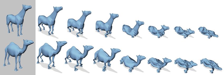
To appear in SIGGRAPH 2004.

           Reference
Source

                                                                                                              Output
Target

                                                      Figure 5: Cat poses retargeted onto a lion.

         Reference
Source

                                                                                                                              Output
Target

                     Figure 6: The horse deformation, collapsing as if it were made of a rubber sheet, is transferred to the camel.

sible while maintaining consistency constraints. For efficiency, we            to the specification of positional constraints only during key events
use a vertex formulation of this problem that satisfies the constraints        such as foot/ground contact. However, a formulation of deforma-
implicitly.                                                                    tion transfer over time would increase the numerical complexity of
    Several limitations of our current system point to directions of           the optimization, requiring a different numerical approach. With
future work. Our method allows limited control over the deforma-               our direct LU solver, we have successfully transfered deformations
tion transfer process in the form of the correspondence map and                onto a target mesh with 400k triangles. However, at this point
vertex constraints, but provides no direct way to fine-tune the so-            the LU solver approaches memory limitations. The LU factoriza-
lution aside from changing the source deformation and reapplying               tion, with a considerable amount of swapping, took 95 seconds, and
deformation transfer. In particular, it cannot transfer the animation          backsubstitution took 6.5 seconds. For extremely large meshes, a
controls used to generate the deformation in the first place. Ideally,         multigrid solver would likely outperform our direct method.
deformation transfer would carry over the controls as well, allowing              Perhaps the most conspicuous limitation of our technique is
the retargeted deformation to be fine-tuned for the target shape. A            the requirement of gross similarity between the source and tar-
general technique to adapt animation control knobs from one char-              get meshes. Transferring deformation between drastically different
acter to another is an open problem in computer graphics.                      meshes is an open problem in computer graphics that presents two
    The optimization problem that we solve is unique up to a global            primary challenges. First, it requires a more versatile technique to
translation. Thus, the global position must always be specified in             relate the source and target to one another that can accommodate
some way by the user. When retargeting only key poses, as in Fig-              ambiguous and arbitrary mappings. Second, it requires a method to
ures 1 and 5, it is easy to resolve the global position by fixing one          appropriately adapt the deformation to the target, rather than simply
vertex in place. However, when retargeting an entire animation se-             transferring it directly without modification.
quence, the position must be specified at each point in time. A po-
sitional constraint specified only during selected intervals (such as
during ground contact) will result in “popping” artifacts when the
constraint becomes active. In the accompanying video, we resolved              Acknowledgments
the issue by constraining the camel’s feet to match the horse’s feet
at each point in time. But, if two meshes have very different pro-             The authors would like to thank Daniel Vlasic for his assistance on
portions, it may be more difficult to formulate an appropriate con-            an earlier version of this project, Ray Jones for his insightful com-
straint.                                                                       ments, Charles Han and Andrew Elliott for their help in preparing
    One way to approach this problem is to directly address the tem-           the figures, and Shuang You for an earlier version of the correspon-
poral dimension in the retargeting process in order to enforce tem-            dence system. This research was sponsored by the Deshpande Cen-
poral coherence as well as reduce the global positioning problem               ter for Technological Innovation.

                                                                           6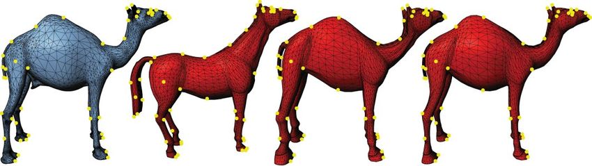
To appear in SIGGRAPH 2004.

         Reference
Source
Target

                                                                                                            Output

                                   Figure 7: Scanned facial expressions cloned onto a digital character.

         Reference
Source
Target

                                                                                             Output

                                             Figure 8: Horse poses mapped onto a flamingo.

References
A LEXA , M., C OHEN -O R , D., AND L EVIN , D. 2000. As-rigid-           L EWIS , J. P., C ORDNER , M., AND F ONG , N. 2000. Pose
   as-possible shape interpolation. In Proceedings of ACM SIG-              space deformations: A unified approach to shape interpolation
   GRAPH 2000, Computer Graphics Proceedings, Annual Confer-                and skeleton-driven deformation. In Proceedings of ACM SIG-
   ence Series, 157–164.                                                    GRAPH 2000, Computer Graphics Proceedings, Annual Confer-
                                                                            ence Series, 165–172.
A LLEN , B., C URLESS , B., AND P OPOVI Ć , Z. 2003. The space of       L ITWINOWICZ , P. C. 1991. Inkwell: A 2 1/2-d animation system.
   human body shapes: Reconstruction and parameterization from              In Computer Graphics (Proceedings of ACM SIGGRAPH 91),
   range scans. ACM Transactions on Graphics 22, 3 (July), 587–             vol. 25, 113–122.
   594.
                                                                         N GO , T., C UTRELL , D., DANA , J., D ONALD , B., L OEB , L., AND
BARR , A. H. 1984. Global and local deformations of solid primi-            Z HU , S. 2000. Accessible animation and customizable graph-
  tives. In Computer Graphics (Proceedings of ACM SIGGRAPH                  ics via simplicial configuration modeling. In Proceedings of
  84), vol. 18, 21–30.                                                      ACM SIGGRAPH 2000, Computer Graphics Proceedings, An-
                                                                            nual Conference Series, 403–410.
B REGLER , C., L OEB , L., C HUANG , E., AND D ESHPANDE , H.
   2002. Turning to the masters: Motion capturing cartoons. ACM          N OH , J., AND N EUMANN , U. 2001. Expression cloning. In
   Transactions on Graphics 21, 3 (July), 399–407.                          Proceedings of ACM SIGGRAPH 2001, Computer Graphics Pro-
                                                                            ceedings, Annual Conference Series, 277–288.
DAVIS , T. A. 2003. Umfpack version 4.1 user guide. Tech. rep.,
  University of Florida. TR-03-008.                                      S EDERBERG , T. W., AND PARRY, S. R. 1986. Free-form defor-
                                                                            mation of solid geometric models. In Computer Graphics (Pro-
G LEICHER , M. 1998. Retargeting motion to new characters. In               ceedings of ACM SIGGRAPH 86), vol. 20, 151–160.
   Proceedings of ACM SIGGRAPH 1998, Computer Graphics Pro-
   ceedings, Annual Conference Series, 33–42.                            S INGH , K., AND F IUME , E. L. 1998. Wires: A geometric
                                                                            deformation technique. In Proceedings of ACM SIGGRAPH
H ERTZMANN , A., O LIVER , N., C URLESS , B., AND S EITZ , S. M.            1998, Computer Graphics Proceedings, Annual Conference Se-
   2002. Curve analogies. In Eurographics Workshop on Rendering             ries, 405–414.
   2002, 233–246.
                                                                         S LOAN , P.-P. J., ROSE , III, C. F., AND C OHEN , M. F. 2001.
H SU , W. M., H UGHES , J. F., AND K AUFMAN , H. 1992. Direct               Shape by example. In Proceedings of the 2001 symposium on
   manipulation of free-form deformations. In Computer Graphics             Interactive 3D graphics, ACM Press, 135–143.
   (Proceedings of ACM SIGGRAPH 92), vol. 26, 177–184.

                                                                     7
You can also read