+RIBRAFT X-POD INSTALLERS GUIDE - Firth Ribraft X-Pod
←
→
Page content transcription
If your browser does not render page correctly, please read the page content below

DECEMBER 2018

+RIBRAFT X-POD
             ®   ®

INSTALLERS
GUIDE
1            Scope                                           3
    2            Description of the System                       3
    1 DPM			                                                     4
        2.1      Concrete                                        4
        2.2      Pods                                            4
        2.3      Mesh                                            6
        2.4      Steel                                           6
        2.5      DPM                                             7
        2.6      Optional Gravel raft                            7
        2.7      Firth HotEdge                                   7
    3            Installation of the system                      7
        3.1      Site/earth works                                7
        3.2      Plumbing                                        7
        3.2.1    Below Slab Plumbing Installation Methodology.   7
        3.3      In Floor Plumbing Installation methodology.     9
        3.4      Recesses for showers.                           11
        3.5      Sub-base/subgrade                               12
        3.6      Formwork setup                                  12
        3.7      DPM placement                                   12
        3.8      Pod installation                                12
        3.9      Reinforcement Placement                         13
        3.10     Concrete Placement                              13
        3.11     Shrinkage Control Joints                        14
        3.11.1   Saw cut joints                                  14
        3.11.2 Free joints                                       14
        3.12     Finish expectations                             15
    4            Installation Documentation                      15

2                                                                     FIRTH RIBRAFT® X-POD® INSTALLERS GUIDE
1   SCOPE                                                          2     DESCRIPTION OF THE SYSTEM

        This installation guide has been developed for the exclusive         The Firth RibRaft® X-Pod® flooring system comprises of:
        use of Firth customers who are experienced in the
                                                                             • Firth concrete mix IP2019X or IP2519X, refer section 2.1
        construction of residential concrete foundation systems.
        The Building Act requires that only suitably qualified               • A matrix of RibRaft® X-Pod® formers to create typically
        persons, who are Licensed Building Practitioners, (LBP)                a total floor thickness of 300mm with ribs at 750 or
        or working under the supervision of a LBP, can construct               1500mm centres and a 85mm minimum topping above
        foundations systems. Experience in the placing finishing               the RibRaft® X-Pod®s. Note refer to the project drawings
        and early age care of concrete in accordance with NZS3109              as designers have differing preferences for topping
        is mandatory.                                                          thickness, refer section 2.2

        The RibRaft® X-Pod® foundation is a specifically designed            • Firth RibRaft® Keystones which lock the X-Pod®s
        systems and as such all details shall be provided in the               into place
        project drawings. These drawing will have been reviewed
                                                                             • Mesh in the topping, refer section 2.3
        as part of the building consent process. Any errors or
        omissions should be brought to the designers attention               • Reinforcement typically in the form of DH10s or larger

        for instruction.                                                       diameter in the ribs, perimeter, and load bearing beams,
                                                                               section 2.4
        Contact your local Firth Representative for supply of
        Firth RibRaft® X-Pod®s. Pods shall be released to site               • DPM providing a vapour barrier between ground and

        upon confirmation of the placement of an order for the                 flooring system, section 2.5

        appropriate Firth concrete mix code (see section 2.1).               • Dependent upon soil conditions the flooring system may
                                                                               sit on a compacted gravel raft, section 2.6

                                                                             • The system is compatible with Firth HotEdge® should
                                                                               slab edge insulation be specified, section 2.7
    FIGURE 1 - THE RIBRAFT® X-POD® SYSTEM

                                                                                                            2
                           7

                               6

                                                                                                                5

                                   4                                                                    1

                                                    3

    1 DPM                                                                  5 Steel reinforcing (bars)
    2 RibRaft® X-Pod® (215/750 or 215/1500)                                6 Steel reinforcing (mesh)
    3 RibRaft® Keystone 8/16                                               7 Firth Concrete (mix code IP2019X or IP2519X)
    4 RibRaft ADJ Pod (215/150.400 and ADJ Pod 215/450.700)
               ®

3                                                                                                    FIRTH RIBRAFT® X-POD® INSTALLERS GUIDE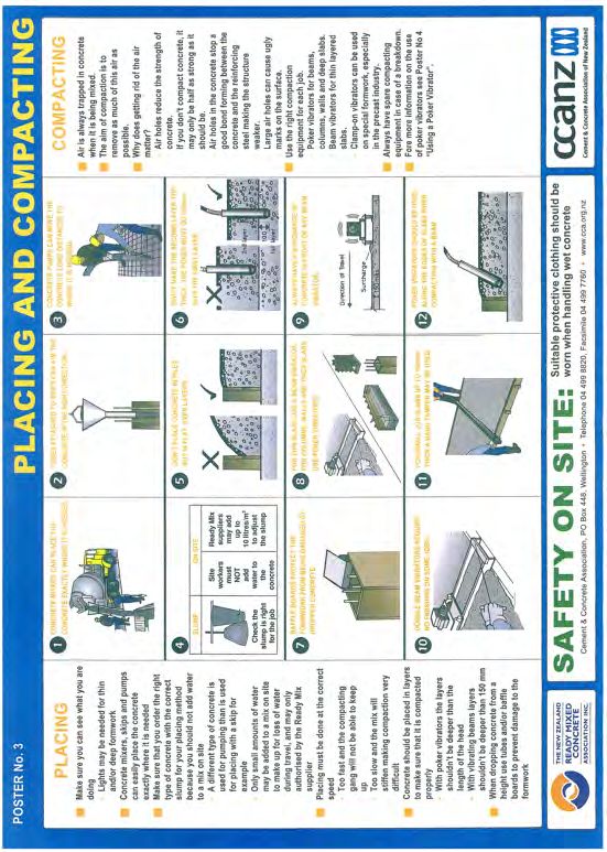
2.1 CONCRETE                                                    2.2 PODS

      RibRaft® X-Pod® Foundation systems require a specific Firth     The Firth RibRaft® X-Pod® flooring system comprises of 4
      designed concrete mix. Choose one of the following:             pod options which are linked using the X-Pod® Keystone clip
                                                                      to create an efficient and strong flooring system.
       1 X-Pod® Mix IP2019X – a 20MPa 120mm slump mix
                                                                      The pod options are:
        available as a pump mix suitable for 100mm pump lines
        available in either a 13mm or more usually a 19mm nominal      • RibRaft® X-Pod® 215/750. These units, when laid out and
        aggregate size, or as a structural (non-pump) mix               linked with the X-Pod® Keystone create a grid with 100mm
                                                                        ribs at 750 centres. The height of the pods are 215mm
       2 X-Pod® Mix IP2519X – a 25MPa 120mm slump mix
                                                                        which when combined with 85mm of concrete topping
        available as a pump mix suitable for 100mm pump lines
                                                                        give a total floor thickness of 300mm.
        available in either a 13mm or more usually a 19mm nominal
                                                                        See Figure 2.
        aggregate size, or as a structural (non-pump) mix. This
        mix shall be specified for buildings constructed in the        • RibRaft® X-Pod® 215/1500. These units, when laid and
        ‘sea spray zone’ (i.e. within 500m of the sea including         linked with the X-Pod® Keystone create a grid with
        harbours, within 100m of tidal estuaries or inlets, on          100mm ribs at 1500 centres. The units are designed to
        offshore islands and elsewhere as defined as exposure           form a cross shaped concrete column in the centre of
        zone D in 4.2.3.3 of NZS3604).                                  the 1500mm rib grid. The height of the pods are 215mm
                                                                        which when combined with 85mm of concrete topping
                                                                        give a total floor thickness of 300mm. See Figure 3.

                                                                       • RibRaft® two part adjustment pod. ADJ Pod
                                                                        (215/150.400 and ADJ Pod 215/450.700). These units can
                                                                        be used when the required spacing between beams and
                                                                        ribs is less than 750mm. The 215/150.400 unit contains a
                                                                        top mounted clip which allows it to be securely connected
                                                                        to other X-Pod® units. Without modification the unit fills
                                                                        a 400mm void. With cutting and overlapping the unit can
                                                                        fill voids of between 150 and 400mm. When combined
                                                                        with the ADJ 215/450.700 unit, voids of between 450 to
                                                                        700mm can be filled. Figure 4 illustrates the units.

    FIGURE 2 - TYPICAL RIBS LAYOUT OBTAINED WITH RIBRAFT® X-POD®S 215/750

                                   750               750

                                                                          750

                                                                          750

        Illustration: © Cresco.co.nz

4                                                                                              FIRTH RIBRAFT® X-POD® INSTALLERS GUIDE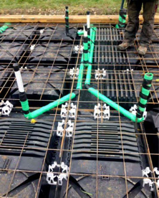
FIGURE 3 - TYPICAL RIBS LAYOUT OBTAINED WITH RIBRAFT® X-POD®S 215/1500

                                                          Illustration: © Ribraftdesign.co.nz

    FIGURE 4 - RIBRAFT® X-POD® TWO PART ADJUSTMENT PODS

                                                                                                                  Illustration: © Ribraftdesign.co.nz

               RibRaft® X-Pod® ADJ 215/150.400                                         RibRaft® X-Pod® ADJ 215/450.700

       Firth RibRaft® X-Pod®s are placed directly on levelled ground and are arranged in such a way as to form a reinforced
       concrete floor slab with a grid of reinforced concrete ribs and edge beams when concrete is placed onto them.
       The RibRaft® ADJ Series X-Pod®s may be used to suit specific architecture layout and also to accommodate services.

       Figure 5 shows how the various X-Pod® components might be utilised on a complex floor arrangement where liquefaction
       or expansive soils are not a consideration.

5                                                                                                       FIRTH RIBRAFT® X-POD® INSTALLERS GUIDE
FIGURE 5 - EXAMPLE OF HOW THE VARIOUS X-POD® COMPONENTS CAN BE UTILISED ON A COMPLEX SHAPED FLOOR

    2.3 MESH                                                         2.4 STEEL

      Mesh shall be Grade 500 and comply with AS/NZS                    The reinforcing bars in the ribs and edge beams shall
      4671:2001. Typically the mesh will be 665 mesh (Class L)          conform to AS/NZS 4671:2001 Grade 500, Class E “Steel
      or SE62 ductile mesh (Class E). The Design Engineer shall         Reinforcing Materials”. The volume of reinforcement shall
      specify the required mesh.                                        be documented on the approved building consented
                                                                        drawings.
      Class L mesh can be used when the sole purpose is
      limitation of crack widths and the ground conditions              The Firth RibRaft® X-Pod® Keystones hold the
      are defined as good in terms of NZS3604. The Class E              reinforcement in positon without the need for tying.
      reinforcing bars in the ribs and beams provides adequate          The X-Pod® Keystone can accommodate up to two DH16
      ductility of the system which allow the use of Class L mesh.      bars at a lap positon.

      Class E shall be used when the mesh preforms a structural
      function such as a slab on ground prone to liquefaction or
      expansive soils.

      Mesh shall be lapped in accordance with NZS3101.

      Two options are available for supporting the mesh which
      shall be defined on the drawings:

       1 The mesh can be supported on mesh chairs to achieve
        cover to the top surface of 35mm. This methodology
        minimises the cover and therefore enhances the crack
        width limiting ability of the mesh.

       2 The mesh can alternatively be laid on upstands provided
        in the corners of the pods. The 15mm upstands on the
        pods mean that cover from the concrete surface to the
        mesh (SE62) is 58mm and slightly less at mesh overlaps.

6                                                                                                FIRTH RIBRAFT® X-POD® INSTALLERS GUIDE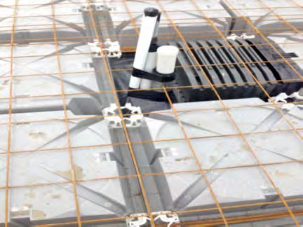
2.5 DPM                                                   3   INSTALLATION OF THE SYSTEM

       The damp proof membrane (DPM) material                     The following provides an overview of the installation of the
       shall be polyethylene sheet in accordance with             Firth RibRaft® X-Pod® system. Where conflict exists between
       NZS 3604:2011. The DPM shall be laid over the              the information provided in this document and the approved
       entire building platform directly on top of a sand         building consent drawing set, the drawings shall take precedence.
       blinding layer, extending to the outside of the edge       However, it is mandatory that the concrete used is supplied by
       beam. The joints shall be lapped not less than             Firth Industries to allow management of quality control.
       50mm and sealed with pressure sensitive tape
       not less than 50mm wide. All penetrations of the
       DPM by plumbing and services or punctures during       3.1 SITE/EARTH WORKS
       construction shall also be sealed with pressure
                                                                  The building footprint shall be excavated to a suitable depth
       sensitive tape. The DPM may extend beyond the
                                                                  to ensure all organic material is removed (top soil, roots etc).
       edge of the slab i.e. underneath the formwork, or
                                                                  Excavation shall extend beyond the footprint a distance shown
       may be folded and stapled up the inside of the
                                                                  on the drawings which is typically twice the depth of compacted
       formwork. The minimum requirement is that the
                                                                  hardfill beneath the concrete slab. Precautions shall be taken to
       DPM extends to the outside of the edge beam. It is
                                                                  prevent silt laden runoff from leaving the site should rain occur.
       very important that the DPM is not bunched up at
       the formwork.

       Where enhanced thermal performance is required,        3.2 PLUMBING

       ThermoX DPM can be used as the DPM.                        Various Territorial Authorities have their own preferences for
                                                                  plumbing details so always check with the local council.

    2.6 OPTIONAL GRAVEL RAFT                                      Two options exist for running plumbing:

       Often a gravel raft is not required below the DPM          • The pipes are installed in the ground below the slab and then

       where ground bearing conditions permit, although             rise up through the slab at the desired location within the

       a sand blinding layer may be required to provide             building, referred to as “below slab installation”. This is the

       puncture resistance to the DPM. Where ground                 preferred option in most situations.

       conditions are soft, a compacted gravel raft can           • The pipes run within the plane of the X-Pod® flooring system,
       be provided to reduce the bearing pressures in               referred to as “in floor installation”.
       the natural ground to acceptable levels. Details of
       any gravel raft shall be provided on the
       project drawings.                                      3.2.1 BELOW SLAB PLUMBING INSTALLATION METHODOLOGY

                                                                  This option is applicable for most situations but should not be used
                                                                  on liquefaction sites for which lateral spread is expected. In most
    2.7 FIRTH HOTEDGE   ®

                                                                  situations this is the norm and most cost effective solution.
       Where additional thermal efficiency is required,
                                                                  For this option, pipes shall be conveyed underground to their plan
       Firth HotEdge® can be incorporated into the design.
                                                                  location then brought up through the X-Pod® and the concrete
       Refer Firth web page for more information.
                                                                  floor slab. The trenching, placing and bedding of the pipes/
                                                                  ducts and the backfilling shall conform to the requirements of the
                                                                  consent documentation. Services shall not be placed within any
                                                                  concrete except to cross that section of concrete i.e. services shall
                                                                  not run along ribs or edge beams. In accordance with
                                                                  AS/NZS3500.4:2015 pipes penetrating through concrete shall be:

                                                                  • Installed at right angles to the slab surface

                                                                  • Lagged with an impermeable material for the full depth of the
                                                                    concrete penetration

                                                                  • Lagging must be at least 6mm thick

                                                                  Any services horizontally crossing ribs or the edge beams shall be
                                                                  placed only within the middle third of the member. At no stage
                                                                  shall any of the reinforcement bars be relocated or cut to allow for
                                                                  the services (it is acceptable, however to cut the mesh). In some
                                                                  instances this will dictate the location of the pods.

                                                                  The X-Pod® ADJ spacers can be used to trim around plumbing
                                                                  penetrations if required.

7                                                                                                  FIRTH RIBRAFT® X-POD® INSTALLERS GUIDE
TYPICAL DETAILS ARE SHOWN BELOW

    Below slab installation
    showing lagging of pipes

                                                            600                                                             600
    Details where large dimeter
                                                                             25                        0
                                                                               0
    pipe required through                                                                           25
                                                                                        350
    perimeter beam

                                                                                                                     2HD10 CRANKED
                                                                  600 MIN.                                           BOTTOM BARS +
                                                                                                                     1HD10 CRANKED

                                                                                                           400
                                                                   2HD10                MIN. CLEARANCE               TOP BAR
                                                                                   25

                                                                   BOTTOM BARS          FOR REINFORCING

                                                                                                                                      RIBRAFT™ X-POD

                                          Ø110 (MAX) PIPE
                                       IN COMPRESSIBLE
                                      LAGGING MATERIAL
                                                                                                                                     RIBRAFT™ X-POD
                                                                                                                                     ADJ 215/150.400

    Use of X-Pod® ADJ pods
    to create zone for pipes to
    penetrate slab

8                                                                                                                FIRTH RIBRAFT® X-POD® INSTALLERS GUIDE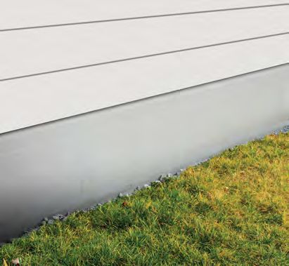
3.3 IN FLOOR PLUMBING INSTALLATION METHODOLOGY

       This is the preferred methodology for sites where lateral spread associated with liquefaction is expected as it provides enhanced
       protection for the pipes compared to the below slab methodology. However, it can be used for all ground conditions.

       Pipes services can be run within the plane of the RibRaft® X-Pod®s either exiting out of the side of the perimeter ring beam
       or going underground near the edge beam. Pipes shall be laid at a fall to comply with NZBC G13/AS1. For pipe up to 65mm
       diameter the minimum gradient is typically 1 in 40, while for 100mm pipes its 1 in 60, however greater falls may be required
       dependent upon the required number of discharge units. Table 1 provides distances from the edge of the slab to pipe surface
       penetration to achieve minimum pipe gradients. Where gradients cannot be achieved, then services will be required to be run
       under the slab.

       Pipes shall either be:

        1 Located to pass perpendicular to the ribs and beams and shall not be laid along the length of ribs or beams. X-Pod®s can be
          cut and sealed as required to achieve the required fall and position.

        2 The adjustable X-Pod® can be used to create beams to run services through. Pipes shall be laid to ensure 15mm concrete
          cover between pipe and reinforcement in the perimeter beam. The width of the rib containing the pipes shall be greater
          than the specified rib width (typically 100mm) plus the pipe diameter. This ensures the rib width is maintained even though
          plumbing pipes run through it. All pipes in contact with concrete shall be lagged with an impermeable material of at least
          6mm thickness.

    TABLE 1 MAXIMUM DISTANCE FROM EXTERIOR TO ENTRANCE POINT OF PLUMBING PIPES

               Pipe Diameter (ID)mm Gradient                                               Maximum distance to edge
               			                                                                           with 215mm thick pod

                                 40                             1 in 40                               3400

                                 50                             1 in 40                               3000

                                 65                             1 in 40                                2400

                             100                                1 in 60                                1200

    TYPICAL DETAILS ARE SHOWN BELOW

    In slab installation pipes
    cut through rib walls

9                                                                                                   FIRTH RIBRAFT® X-POD® INSTALLERS GUIDE
Use of X-Pod® ADJ pods to
     create zone for pipes to run
     without compromising Ribs

     Typical drop down detail for sewer                                                       Ø110 (MAX) PIPE

     line to prevent it being visible at
                                                                           FLEXIBLE SEALANT              COMPRESSIBLE
     exterior of slab                                                       AROUND THE PIPE              LAGGING MATERIAL

                                                                                    F.F.L.

                                           STOP BARS EACH SIDE
                                           OF PIPE, INSTALL HD12
                                           BARS X 1500 mm LONG

                                                                                                        USE ADJUSTABLE EDGE PODS
                                                                                                        LOCALLY TO GIVE PIPE SLEEVE
                                                                                                        A MIN. OF 100 mm CONCRETE COVER
                                                       SEAL DPM PENETRATION

                                                                   FLEXIBLE JOINT

10                                                                                                 FIRTH RIBRAFT® X-POD® INSTALLERS GUIDE
3.4 RECESSES FOR SHOWERS
The following figures provide typical details for recesses and large penetrations.
Shower recess distant
from slab edge
Shower recess close
to slab edge
Large penetration
through slab
11 FIRTH RIBRAFT® X-POD® INSTALLERS GUIDE3.5 SUB-BASE/SUBGRADE 3.8 POD INSTALLATION
Excavated material shall be replaced with hardfill material The drawing should be reviewed to determine whether the
compacted in maximum layers of 150mm or as specified symmetrical RibRaft®.
by the design engineer. Refer specific project drawings/
X-Pod® 750/215 is specified or the non-symmetrical
specification for minimum hardfill layer under slab. A
1500/215 pod. Review of the 1500/215 pod will show that
blinding layer of 0-5 mm sand or crusher dust shall cover
only two of the sides only will create a 100mm rib.
base material to a maximum thickness of 25mm (for
final hand screeding). The finished level of compacted Place a row of RibRaft® X-Pod®s the specified distance
hardfill shall be determined specifically by the designer away from the formwork (refer consent drawings). Click in
for each site. The subgrade/sub-base should be inspected X-Pod keystones along perimeter beam to secure in place.
by the design engineer when this is a condition of the Align second row of X-Pod®s and clip together in groups
building consent, or where concerns exist that the ground of four pods with X-Pod® Keystone in the holes provided.
conditions are not those implied by the design. The X-Pod® Keystones click into place. Continue placing
X-Pod®s and clicking together with X-Pod® Keystones.
Note the pods are securely held together and modest
realignment can occur by pushing. However, take care to
3.6 FORMWORK SETUP avoid damage to the DPM.
Perimeter shutters shall be set to profiles or string lines Where adjustment pods are specified, or where required to
with top edge at Finished Floor level. Setting level of frame around a plumbing penetration, follow the following
shutters must allow for variation across prepared base procedure, refer Figure 6.
and final hand screed of sand blinding layer (to +/- 5mm).
Shutters shall be adequately braced to ensure minimal FIGURE 6 RIBRAFT® X-POD® TWO PART
movement occurs under full load of wet vibrated concrete ADJUSTMENT PODS
and construction loadings. Forms shall prevent the leakage
of grout at joints which can result in a bony surface finish.
The finished floor level shall ensure that the height above
ground level satisfies the greater requirements of:
Clip
• E1/AS1, refer section 2 in particular
• E2/AS1, refer section 9.1 in particular
• any local flood management clearance criteria
The specified levels shall be shown on the project drawings.
Location nib
3.7 DPM PLACEMENT
The DPM shall be laid over the entire building platform Cutting guidance
directly on top of a sand blinding layer, extending to the
outside of the edge beam. The joints shall be lapped not RibRaft® X-Pod® ADJ 215/150.400
less than 50mm and sealed with pressure sensitive tape
not less than 50mm wide. All penetrations of the DPM by
plumbing and services or punctures during construction
shall also be sealed with pressure sensitive tape. The DPM
may extend beyond the edge of the slab i.e. underneath
the formwork, or may be folded and stapled up the inside
of the formwork. The minimum requirement is that the
DPM extends to the outside of the edge beam. It is very
important that the DPM is not bunched up at the formwork.
ThermoX DPM is highly reflective and sunglasses should be
used when installing on sunny days. The reflective side is
placed upwards.
RibRaft® X-Pod® ADJ 215/450.700
Illustration: © Ribraftdesign.co.nz
12 FIRTH RIBRAFT® X-POD® INSTALLERS GUIDEWhere a 400mm gap needs filling use the ADJ/215/150.400 pod. Simply clip the alignment clip into the recess provided in the
RibRaft® X-Pod®.
Where the required extension width is between 150 and 350mm (in 50mm increments), the ADJ 215/150.400 pod requires
cutting. The location of the required cuts are shown on the side of the adjustment pod. For 150 to 200mm extensions two cuts
are required, while for 250 to 350mm extensions only one is required. Once cut, clip the clip end into the recess in the X-Pod®
and overlay the other end to provide a stop end.
For extension requirements of 450 to 700mm clip the ADJ 215/150.400 into the X-Pod® and overlay the ADJ 215/450.700 to
achieve the required extension. Aligning the extension number on the side of 215/450.700 pod with the location nib on the ADJ
215/150.400 pod will achieve the required extension in 50mm increments.
The holes on the sides of the extension pods are designed to accommodate the X-Pod® Keystone if required.
3.9 REINFORCEMENT PLACEMENT
The X-Pod® Keystones have been designed to securely hold reinforcement in positon without the need for tying. Place
reinforcement in the location and to the details shown on the drawing. Clip reinforcement into place in X-Pod® Keystones.
Mesh can either be placed on reinforcement chairs or supported on the upstands in the corner of each X-Pod®. Refer to the
drawings to determined which mesh support mechanism is specified for a particular project to determine the preference of the
design engineer.
3.10 CONCRETE PLACEMENT
Firth concrete mix IP2019X or IP2519X are the most commonly specified mix designs for X-Pod® floors. The volume of the
concrete floor above the pods can be estimated by calculating the overall volume including the pods (typically 750x750x300)
and deducting the volume of the X-Pod®s provided in Table 2.
TABLE 2 VOLUME OF RIBRAFT® X-POD®S
Type of X-Pod® Volume (litres)
215/750 83
215/1500 91
The Firth concrete mix is designed to have a suitable strength at a higher slump. The mix has been formulated to achieve
appropriate filling of the X-Pod® foundation system. Pumping concrete is the recommended method of delivering the fresh
concrete to the work face. Other methods of delivery may be suitable however approval from Firth or project engineer is
required. For placing and finishing guidelines refer below and to CCANZ’s posters number 3 and 5.
1 It is generally preferable to start pour at the garage (allows a harder, flatter finish) and work away. Controlling the flow
from the pump nozzle is important to ensure even coverage.
2 Follow behind pour face with immersion (spud) type vibrator to all concrete (beams, ribs and top slab).
3 Care must be taken around plumbing to ensure damage, or movement does not occur.
4 Following vibration, normal concrete finishing techniques shall be carried out (refer poster number 5). Screed off concrete
using normal screeding tools or vibrating screeds. Bull float to push down aggregates left at the surface during the
screeding operation. Finish the edges with steel trowel and the interior of the slab surface with troweling machines. It is
important that final troweling does not commence until all the bleed water has evaporated as premature commencement
of troweling can lead to surface delamination or dusting.
13 FIRTH RIBRAFT® X-POD® INSTALLERS GUIDE5 Hot and/or windy conditions present during pouring/finishing require steps be taken for the protection of the concrete to
prevent plastic cracking. Protection measures include:
a Aliphatic alcohol sprays
b Water vapour misting over surface (ie from water blaster directed upward, and wind carrying mist over slab surface).
However this water must be fully evaporated from the surface before commencing trowelling.
c Positioning wind breaks
6 Curing the slab is crucial to ensure strength gain of concrete and protection from early age cracking. Suitable methods of
curing include:
a Water spraying/ponding
b Curing membrane sprays
c Polythene covering
7 If environmental conditions forecast greater than 12 degrees variation of day time to overnight temperatures, then
measures to protect slab from thermal shock shall be employed, these include:
a Planning the pour time to minimise the temperature variations the concrete will experience
b Covering surface with fabric, plastic covers or polythene
c Using early entry saws
Forms shall not be struck on the day of the pour, and consideration should be given to leaving forms in place for 2-3 days
following pour in very cold or shaded locations.
3.11 SHRINKAGE CONTROL JOINTS
Shrinkage control joints reduce the risk of unwanted cracks, and their placement needs to be carefully considered
where uncontrolled cracking could be unacceptable. Two types are described here, saw cut joints (which are tied joints)
and free joints.
3.11.1 SAW CUT JOINTS
Saw cuts are located at positons in which the concrete is likely to crack due to stresses induced by restrained shrinkage.
The aim of providing them is for the concrete to crack at the bottom of the saw cut thus minimizing the potential for a visible
crack wandering over the surface. The level of reinforcement provided in a RibRaft® X-Pod® flooring system mean that cracks
have no structural implications being only an aesthetics issue. Factors to consider are the type of floor finish, the location of
ribs and ground beams.
When warm sunny days are followed by cool nights, the change in temperature can cause cracking. Hence preference should
be given to using early entry saws which are used immediately after finishing. Shrinkage control joints cut using diamond
blades shall be cut as early as possible which is typically within 24 hours of hardening in summer, and 48 hours in winter. They
shall be cut to a depth of 25mm. Shrinkage control joints do not guaranteed to eliminate all visible or unwanted cracks.
Joints shall be positioned to coincide with major changes in floor plan. Where concrete is to be exposed, for example in a
garage, or brittle covering placed over, the maximum intermediate bay sizes shall be limited to 5m. Bay dimensions formed by
shrinkage control joints shall be limited to a maximum ratio of length:width of 1.5:1. Where a shrinkage control joint runs along
the line of a load bearing rib, then the joint shall be located directly above one edge of that rib.
In order to limit the width of cracks at re-entrant, or internal corners, extra steel is often specified and is placed on top of the
mesh. These are typically 2-HD12 bars (grade 500E), 1200mm long tied to the top of the mesh at 200mm centres, with 50mm
cover to the internal corner – refer Building Consent drawing for details.
3.11.2 FREE JOINTS
For large plan areas the designer may specify free joints. These are typically joints which allow unrestrained movement,
but are doweled to prevent vertical movement. If specified then follow details shown on the building consent drawings.
14 FIRTH RIBRAFT® X-POD® INSTALLERS GUIDE3.12 FINISH EXPECTATIONS
The Building Amendment Act 2013 introduced new consumer protection measures which became effective on
1 January 2015. MBIE has developed guidance to the industry on what constitutes a defect and the definition of acceptable/
unacceptable defects. The MBIE guidance document suggest that for a concrete floor it is recognised that some cracking
in concrete is common and not necessarily a sign of poor workmanship. The document suggests that cracks up to 3mm
wide are acceptable.
It is also recognises that the levelness of the floor is important. NZS3114 requires an even plane within ±5mm for every 3m
direction for a carpeted floors and ±3mm for tiled and vinyl floors. Individual mounds should be less than 3mm high and
depressions less than 3mm deep. In additional no abrupt deviations greater than specified in NZS3114 should exist.
Visible reinforcing or bony concrete should not exist along the slab edge.
Concrete is a natural material and shade variation can be expected. Often slight colour variations will fade with time.
4 INSTALLATION DOCUMENTATION
When requested, the installation contractor shall provide a PS3 for the installation of the Firth RibRaft® X-Pod® floor.
Confirming that construction was in accordance with the project drawings and that the concrete used for the project was
supplied by Firth Industries.
15 FIRTH RIBRAFT® X-POD® INSTALLERS GUIDE16 FIRTH RIBRAFT® X-POD® INSTALLERS GUIDE
17 FIRTH RIBRAFT® X-POD® INSTALLERS GUIDE
© Firth Industries 2018. All rights reserved. Content in this document is protected under the Copyright Act 1994. No material may be reproduced in whole or in part without the written consent of the copyright holder.

                  0800 FIRTH 1                                                                                                    PRODUCTSPEC
                  FIRTH.CO.NZ                                                                                                         productspec.net                                 masterspec.co.nz
You can also read