Robo-AO: autonomous and replicable laser-adaptive-optics and science system
←
→
Page content transcription
If your browser does not render page correctly, please read the page content below
Robo-AO: autonomous and replicable laser-adaptive-optics and
                           science system
  C. Baranec*a, R. Riddlea, A. N. Ramaprakashb, N. Lawc, S. Tendulkara, S. Kulkarnia, R. Dekanya,
          K. Buia, J. Davisa, M. Burseb, H. Dasb, S. Hildebrandta, S. Punnadib & R. Smitha
  a
  Caltech Optical Observatories, California Institute of Technology, 1200 E. California Blvd., MC
  11-17, Pasadena, CA, USA 91125; bInter-University Centre for Astronomy & Astrophysics, Post
   Bag 4, Ganeshkhind, Pune, India 411 007; cDunlap Institute for Astronomy and Astrophysics,
          University of Toronto, 50 St. George Street, Toronto M5S 3H4, Ontario, Canada

                                                       ABSTRACT

We have created a new autonomous laser-guide-star adaptive-optics (AO) instrument on the 60-inch (1.5-m) telescope at
Palomar Observatory called Robo-AO. The instrument enables diffraction-limited resolution observing in the visible and
near-infrared with the ability to observe well over one-hundred targets per night due to its fully robotic operation. Robo-
AO is being used for AO surveys of targets numbering in the thousands, rapid AO imaging of transient events and long-
term AO monitoring not feasible on large diameter telescope systems. We have taken advantage of cost-effective
advances in deformable mirror and laser technology while engineering Robo-AO with the intention of cloning the
system for other few-meter class telescopes around the world.
Keywords: Adaptive optics, lasers, wavefront sensing, astronomy, robotics

                                                1. INTRODUCTION
Robo-AO is a new autonomous laser-guide-star adaptive-optics (AO) and science instrument currently deployed on the
60-inch telescope at Palomar Observatory. The instrument has demonstrated wavefront correction sufficient for
diffraction-limited resolution imaging, 0.1"-0.25", at visible and near-infrared wavelengths over a field as large as 44" ×
44". Robotic software automations1 keep target-to-target observing overheads of < 2 minutes (including slew time)
which leads to the ability to observe over one-hundred targets per night. While several initial scientific results are in
press2 and in preparation, we are continuing to exploiting this capability to execute extremely large targeted AO
surveys3,4, rapid AO imaging and characterization of transient events5 and long-term AO monitoring6,7 not otherwise
feasible on large telescope AO systems8. The first of many envisioned systems is currently executing a 30-night science
demonstration period at the 60-inch telescope before supporting seven competitively selected programs, over 21 nights,
in the 2012B semester. Three other implementations of Robo-AO are in various stages of development: work on a clone
of Robo-AO for the 2-m IUCAA Girawali Observatory near Pune, India is underway; a natural guide star only system
for the 1-m Table Mountain telescope, led by Pomona College, has recently closed their AO loop on sky; and a system
dedicated to precision near-infrared astrometry is being studied for deployment at the South Pole.

                            2. DESCRIPTION OF THE ROBO-AO SYSTEM
The Robo-AO system comprises several main systems: a robotic host telescope; the laser system; support electronics
including the master robotic control computer; and a Cassegrain mounted adaptive optics system with integrated science
instruments (see Fig. 1).
          The first Robo-AO system has been deployed on the Palomar 60-inch telescope. The telescope was upgraded
with full robotic control in 2004, permitting local or remote operation via TCP/IP commands9. In addition, the telescope
uses data from a locally hosted weather station to execute automated routines to ensure telescope safety during adverse
weather conditions.
          The core of the Robo-AO laser system is a pulsed 10-W ultraviolet laser (JDSU Q301-HD) mounted in an
enclosed projector assembly on the side of the telescope. The laser projector incorporates a redundant shutter in addition
to the laser’s internal shutter for additional safety; a half-wave plate to adjust the angle of projected linear polarization;
___________________________________________________________________
*baranec@astro.caltech.edu; phone 1 626 395 8377; http://www.astro.caltech.edu/Robo-AO/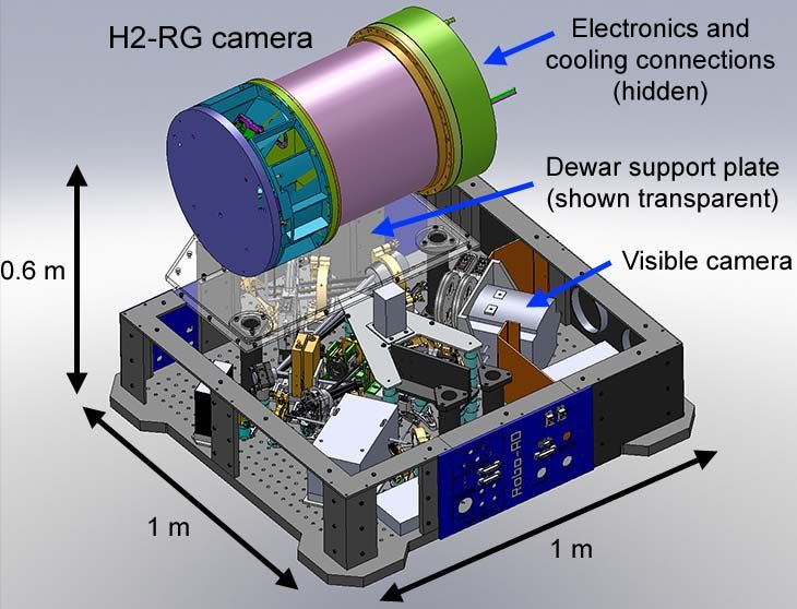
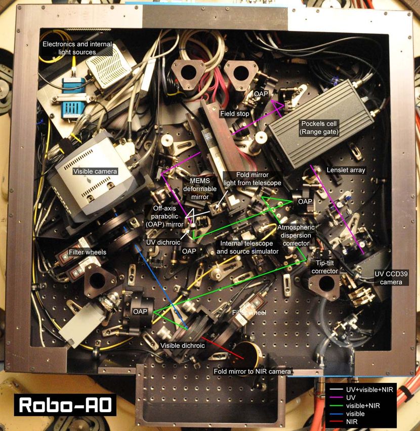
Figure 1.The Robo-AO laser adaptive-optics system. The adaptive optics and science instruments are installed at the
    Cassegrain focus of the robotic 60-inch telescope at Palomar Observatory. The laser system and support electronics are
    attached to opposite sides of the telescope tube for balance.

and an uplink tip-tilt mirror to both stabilize the apparent laser beam position on sky and to correct for telescope flexure.
A bi-convex lens on an adjustable focus stage expands the laser beam to fill a 15 cm output aperture lens, which is
optically conjugate to the tip-tilt mirror. The output lens focuses the laser light to a line-of-sight distance of 10 km.
Within the adaptive-optics instrument, a high-speed beta-BaB2O4 Pockels cell optical shutter (FastPulse Lasermetrics10)
is used to transmit laser light only returning from a ~400-m slice of the atmosphere around the 10 km projector focus,
resulting in the laser appearing as a spot. Switching of the Pockels cell is driven by the same master clock as the pulsed
laser, with a delay to account for the round trip time of the laser pulse through the atmosphere.
          The ultraviolet laser has the additional benefit of being invisible to the human eye, primarily due to absorption
in the cornea and lens11. As such, it is unable to flash-blind pilots and is considered a Class 1 laser system (i.e. incapable
of producing damaging radiation levels during operation and exempt from any control measures12) for all possible
exposures of persons in overflying aircraft, eliminating the need for human spotters located on site as normally required
by the Federal Aviation Authority within the U.S.13. Unfortunately, the possibility for the laser to damage some satellites
in low Earth orbit may exist. For this reason, it is recommended for both safety and liability concerns to coordinate laser
activities with an appropriate agency (e.g., with U.S. Strategic Command within the U.S.14).
          High-order wavefront sensing is performed with an 11×11 Shack-Hartmann wavefront sensor. The detector is
an 80×80 pixel format E2V-CCD39 optimized for high quantum efficiency at the laser wavelength (71.9%) and is paired
with a set of SciMeasure readout electronics. The detector is binned by a factor of 3. Each Shack-Hartmann subaperture
is imaged with 2×2 binned pixels projected to a 5"×5" field of view (limited by a circular 4.8" diameter field stop). The
frame transfer time is 500 µs, with frame exposures of 833 µs, corresponding to an effective frame rate of 1.2 kHz. The
measured read-noise in this mode is ~6.5 electrons per pixel. The laser return signal ranges from 100 to 200
photoelectrons per subaperture per frame (depending on seeing conditions and elevation of observations), equivalent to a
signal-to-noise ratio on each slope measurement of 6 to 10.
          The wavefront reconstructor matrix is a synthetic modal reconstructor based on the disk harmonic functions15
up to the 11th radial order, for a total of 75 controlled modes. The AO control loop is based on a simple integral
controller with a leaky integrator to a median flat position. Individual modal gain optimization has been performed using
on-sky telemetry; however it was found that an overall loop gain of 0.6 was close to optimal in a majority of situations.
The closed-loop bandwidth of the system is approximately 90-100 Hz. The tip- tilt modes measured in the wavefront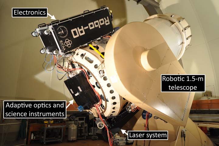
sensor are dominated by mechanical vibration and pointing errors. The tip-tilt signal is used to drive the laser system’s
uplink tip-tilt mirror, thus keeping the Shack-Hartmann pattern centered on the wavefront sensor.
         The high-order wavefront corrector within Robo-AO is a micro-electro-mechanical-systems (MEMS)
deformable mirror16 (Boston Micromachines Multi-DM). Robo-AO uses 120 of the 140 actuators to adjust the
illuminated surface of the mirror, sufficient in spatial resolution to accurately fit the calculated correcting shape. The
actuators have a maximum surface deviation amplitude of 3.5 μm which corresponds to optical phase compensation of
up to 7 μm. In typical seeing at Palomar observatory (median ~1.1"), this compensation length is greater than 5-sigma of
the amplitude of the turbulence induced optical error and therefore results in significant correction headroom.
Furthermore, the deformable mirror is used to compensate for static optical errors arising from the instrument and
telescope at the cost of reduced dynamic range.

    Figure 2. The Robo-AO adaptive optics system and science instruments. Light focused from the telescope secondary mirror
    enters through a small hole at the center of the instrument before being reflected by 90 degrees by the first fold mirror
    towards an off-axis parabolic (OAP) mirror. This mirror images the telescope pupil on the deformable mirror surface. After
    reflection from the deformable mirror, an UV dichroic splits off the laser light (violet) and directs it to the laser wavefront
    sensor. An additional reversed OAP mirror within the wavefront sensor corrects the non-common path optical errors
    introduced by the 10 km conjugate focus of the laser reflecting off of the first OAP mirror. The visible and near-infrared
    light (green) passing through the UV dichroic is relayed by a pair of OAP mirrors to the atmospheric dispersion corrector.
    The light is then reflected by the tip-tilt correcting mirror to a final OAP mirror which focuses the light towards the visible
    dichroic. The visible dichroic reflects the visible light (blue) to the electron-multiplying CCD and transmits the near-infrared
    light (red) to a fold mirror and ultimately to the infrared camera. The combined UV, visible and near-infrared light from the
    telescope and source simulator can be directed to the adaptive optics and science instruments by translating the first fold
    mirror out of the way.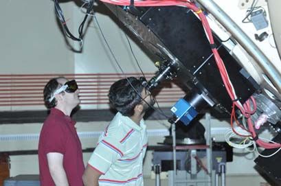
Robo-AO uses four off-axis parabolic (OAP) mirrors to relay a 2ꞌ diameter full field of view from the telescope
to the science cameras achromatically. The relay path includes a fast tip-tilt correcting mirror as well as an atmospheric
dispersion corrector (ADC)17 comprised of a pair of rotating prisms. At the end of the OAP relay is a visible dichroic that
reflects light of λ < 950 nm to an electron-multiplying charge-coupled device camera (EMCCD; Andor iXon 888) while
transmitting infrared light towards an engineering grade infrared camera (Xenics Xeva-1.7-320). The EMCCD camera
has the ability to capture images with very low electronic (detector) noise18,19, at a frame rate which reduces the intra-
exposure image motion to below the diffraction-limited angular resolution. By re-centering and stacking a series of these
images, a long-exposure image can be synthesized with minimal noise penalty. The EMCCD camera can also be used to
stabilize image motion on the infrared camera; measurements of the position of an imaged astronomical source can be
used to continuously command the fast tip-tilt to re-point the image to a desired location. Ahead of each camera is a set
of filter wheels with an appropriate set of astronomical filters.
          An internal telescope and source simulator is integrated into the Robo-AO system as a calibration tool. It can
simultaneously simulate the ultraviolet laser focus at 10 km and a blackbody source at infinity, matching the host
telescope’s focal ratio and exit pupil position. The first fold mirror within Robo-AO directs all light from the telescope’s
secondary mirror to the adaptive-optics system. The fold mirror is also mounted on a motorized stage which can be
translated out of the way to reveal the internal telescope and source simulator.

                            3. ON-SKY ADAPTIVE OPTICS CORRECTION
Robo-AO offers several distinct LGS observation modes, targeting different areas of wavelength and sky coverage
parameter space, distinguished by use of either an on-axis science target or a nearby field star for tip-tilt wavefront
sensing. Currently, we achieve the best visible-light Robo-AO performance by using post-facto shift-and-add image
processing algorithms that mitigate residual atmospheric tip-tilt errors. This requires a source brighter than an in-band
magnitude of m ~ 13.5 for effective post-processing. The future low-noise wide-field infrared camera (described in
section 5.1) will allow Robo-AO to observe in the visible at the diffraction limit using much fainter tip-tilt stars. When
estimating tip-tilt from the science target using the infrared camera, Robo-AO will be able to achieve diffraction-limited
visible-light performance for point sources as faint as mV = 17 in median conditions (Table 1 presents detailed
performance calculations). When using an off-axis near-infrared field star for tip-tilt and assuming the minimum field of
the H2-RG camera, approximately 30% sky coverage can be accessed at the cost of up to an additional 0.23” of RMS
tip-tilt (two-axis) error to be added in quadrature. For 90% sky coverage, there is an additional (up to) 0.35” of RMS tip-
tilt error, providing the equivalent of exquisite seeing over nearly the entire Northern sky.
           We have maintained detailed error budgets for the expected adaptive optics performance of Robo-AO under
different observing conditions (see Table 1). The error budgets use measured Cn2(h) profiles from an onsite MASS-
DIMM atmospheric turbulence monitor collected over a year. These error budgets are based on our team’s considerable
real-world experience building and commissioning AO systems at Palomar and MMT, and in measuring the
performance of the Keck AO system. At Palomar, we find delivered LGS Strehl performance is usually within 10%
(relative) of our detailed model predictions, giving us strong confidence in our performance predictions for Robo-AO.
We expect dramatic image improvement in all conditions at infrared wavelengths, and access to visible near-diffraction-
limited imagery under median conditions. During 25th best percentile seeing, Robo-AO achieves appreciable Strehl
ratios in the visible red wavelengths operating up to 40° in zenith angle. As seeing conditions degrade, the available sky
fraction for visible correction decreases. However, even under poor conditions (75th percentile seeing), very reasonable
correction in the NIR can still be achieved within 10° of zenith. For guide sources brighter than mV=15, H-band Strehl
ratio performance is limited by high-order wavefront errors from the laser system. Beyond mV=17, tip-tilt errors start to
dominate, affecting the overall AO correction.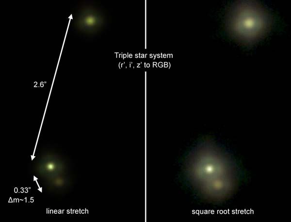
Table 1. Example error budget for Robo-AO under different seeing conditions (r0) and for different zenith angles (z)
    assuming an on-axis mV=17 star for tip-tilt sensing and on-axis science target. Measurement error arises from finite laser
    photoreturn, WFS read noise, sky noise, dark current, and other factors. Focal anisoplanatism is an error arising from the
    finite altitude of the Rayleigh LGS resulting in imperfect atmospheric sampling. Multispectral error arises from differential
    refraction of UV and visible/NIR rays and grows rapidly for large off-zenith angles. For extended targets an additional 65
    nm RMS of angular anisoplanatism error would be present at a field position 10 arcseconds removed from the direction of
    the LGS (finite aperture effects on the 1.5 m telescope mitigate the classical calculation of isoplanatic angle). ‘mas’ indicates
    milli arc seconds, '' indicates arc seconds.

         As validation of our high-order wavefront error budget, we have captured fast frame rate visible data (≥ 30Hz)
and simulated a long exposure by using post-facto tip-tilt correction on the recorded data (this method of visible-only
observing is empirically limited to targets of SDSS band magnitudes of ~13.5 or brighter). Our best post-facto tip-tilt
corrected stellar image during early commissioning in 2011, was of 61 Cyg A, with a Strehl ratio of 14% in r’-band
(λ=620 nm), corresponding to a residual high-order wavefront error of 140±9 nm RMS and 0.10” FWHM. This was
taken during a time of less-than-median seeing, ~1.3”. During typical observing (e.g. Figs. 3, 5 and 6), where objects are
generally scattered around the sky, we generally obtain residual wavefront errors in the 160 to 200 nm RMS range as
indicated by the image analysis of Fig. 4 (see Table 2). This level of wavefront correction leads to a modest ability to
detect and characterize stellar companions at visible wavelengths (see Fig. 4).

    Table 2. Measured image quality metrics from the upper star in Figure 3. The brightest star in the field (leftmost) was used
    for post-facto image registration.
                                        λ (nm) FWHM Strehl RMS WFE (nm)
                                          625      0.11"      7.1%           161
                                          765      0.12"     14.7%           168
                                          890      0.14"     20.4%           178
Figure 3: Robo-AO observation of a triple star system in r’-, i’- and z’-band. Figure 4. Measured 5-sigma contrast ratio versus field separation on a typical observation of a target brighter than m~13.5. This allows for the detection and characterization of binary and multiple systems (e.g. Fig. 6).
Figure 5. Binary star systems imaged in the visible and near-infrared by Robo-AO.

    Figure 6. Left: A 44" × 44" field-of-view, 2-minute long seeing-limited image of the core of the globular cluster Messier 3
    in z-band (λ = 830 – 950 nm). The same image shown with Robo-AO adaptive optics correction.

                        4. EDUCATIONAL AND SYNERGISTIC ACTIVITIES
4.1 Student education
The Robo-AO collaboration is specifically interested in targeting undergraduate education to encourage promising
students to continue into graduate programs emphasizing science and technology. In our group, students learn through
inquiry, helping senior researchers identify questions fundamental to both the astronomy and the engineering that we
undertake. Student participation is organized around research projects that they help identify and then complete.
          Robo-AO has already involved 10 undergraduates through Caltech’s Summer/Minority Undergraduate
Research Fellowship (SURF/MURF) program which supports undergraduates for ten weeks of guided research
alongside a diverse peer group. Our students have made major contributions to the Robo-AO project. As an example,
during the summer of 2011, two students worked separately on an intelligent queue scheduler and real-time telemetry
analysis and display tools respectively; both of their projects were tested by the students at the P60 during a Robo-AO
commissioning run in August 2011. This summer, students are developing software to provide photometric quantities,
image quality and companion detection for fast evaluation; evaluating the limitations of HgCdTe detectors for precision
astrometry which will be later used in the new Robo-AO infrared camera; and evaluating the current astrometric
capabilities of Robo-AO by analyzing hours of visible-light observations of star clusters.
4.2 Synergistic projects
We have established an educational collaboration with Pomona College which has proven to be particularly fruitful. This
collaboration inspired the creation of a new AO lab at Pomona aimed at hands-on education of undergraduates, and the
deployment of a natural-guide-star version of Robo-AO on their 1-m telescope at Table Mountain. As part of the
ongoing collaboration, the Robo-AO has supplied the Pomona AO system with the full real-time Robo-AO software
engine. The prototype Pomona system, dubbed ꞌKAPAO-Alphaꞌ, which demonstrates the basic operation of a natural
guide star adaptive optics system has recently closed the AO loop on-sky and their results have recently been reported20.
The final KAPAO system (no ꞌAlphaꞌ), which will be a remote-access system offering simultaneous dual-band,
diffraction-limited imaging at visible and near-infrared wavelengths, delivering an order-of-magnitude improvement in
point source sensitivity and angular resolution relative to the current seeing limits is in development and is expected to
be deployed in the near future21. Beyond the expanded scientific capabilities enabled by AO-enhanced resolution and
sensitivity, the interdisciplinary nature of the instrument development effort provides an exceptional opportunity to train
a broad range of undergraduate STEM students in AO technologies and techniques. The Pomona Table Mountain AO
system is an exciting example of how Robo-AO can expand the interaction between research and learning through
adaptive optics.
4.3 Outreach
The Robo-AO collaboration has published a web site detailing the goals, science and technical details of the project,
geared towards accessibility to the general public: http://www.astro.caltech.edu/Robo-AO/. Updates are provided,
highlighting major project milestones.
Dissemination of results to the broader public, including interpretation of science discovery and its impact on
society, are made to the public by Palomar Observatory’s Visitor Center
(http://www.astro.caltech.edu/palomar/exhibits/) which draws over 100,000 visitors annually. A web-based kiosk
presentation highlighting adaptive optics science is on display in the Visitor Center and available on the web. The
observatory has also embraced other online social media, and the results Robo-AO commissioning have appeared on
Palomar Observatory’s blog and Facebook page.
In addition, Robo-AO has recently been augmented with an eyepiece for the direct viewing of visible-light
adaptive optics corrected astronomical objects (Fig. 7). The eyepiece is fed by a selectable visible beam splitting mirror
mounted on a removable kinematic base between the visible dichroic and visible filter wheels. This allows for
simultaneous imaging with the visible camera. While access is currently limited, we intend to support future eyepiece
observing by visiting astronomy classes from Caltech and Pomona College.
Figure 7. Members of the Robo-AO team observing Mars with the eyepiece attached to Robo-AO (left). Simultaneous i-
band images of Mars captured without adaptive optics correction (middle) and with the Robo-AO system running (right).
5. FUTURE WORK
5.1 Infrared camera upgrade
The Robo-AO collaboration is currently in the process of upgrading the infrared imaging system from an engineering
grade camera to a low-noise wide-field imager using a 2.5 μm cutoff Teledyne HAWAII-2RG™/HgCdTe detector (H2-
RG). The science grade H2-RG detector has ~ 0.01 e-/sec dark current, < 5 e- readout noise22 and slightly higher
quantum efficiency than the InGaAs, offering 45-80 times more sensitivity (Table 3).The new camera will consist of asimple reimaging system with cold stop and filters (JHK, H-br, CH4 on & off, a blank, and a spare) at the internal pupil
plane. The H2-RG detector (on order and to be delivered) has a guaranteed useable area of 780×780 pixels. We have
adopted a plate scale of 0.086”/pixel, Nyquist at J-band, corresponding to a 67”×67” field, although we will transmit the
full 2ꞌ field to the detector if a larger useable area of the detector is delivered.
Table 3. Optical format and infrared sensitivity of the Robo-AO InGaAs and H2-RG infrared cameras.
Detector Field of view Plate Scale J sensitivity1 H sensitivity1 K (λ=2.2 um) sensitivity1
InGaAs 32.0”×25.6” 0.10”/pixel 14.9 15.2 N/A
H2-RG > 67”×67” < 0.086”pixel 19.7 19.4 18.2
1
Faintest magnitude to reach a signal-to-noise ratio of 10 in 120 s of exposure. These assume a residual wavefront error of
185 nm RMS, expected AO performance under median seeing conditions (table 1).
The Robo-AO instrument has an external camera port (Fig. 8) designed to accommodate an instrument matched
to the expected 70-kg mass of the camera.
Furthermore, as part of our integration plan, we will develop automated routines for configuring the high-speed
NIR tip-tilt sensing and recording of NIR science data in much the same way as has been done with the visible Robo-AO
camera. Special procedures for dealing with infrared data, including taking sky-flats, backgrounds, and darks, as well as
compensating for nonlinear responses and amplifier glow, will be developed and included as part of a standard data
pipeline. We will also maintain a flexible FITS header for all data captured with Robo-AO’s NIR and visible cameras,
making it Virtual Observatory-compliant as recommended in the Astro-2010 Decadal survey23 for possible later public
release and archiving.
Figure 8. Solidworks model of the as-built Robo-AO system with a model of the Keck infrared tip-tilt sensor (similar in
function, size and weight to the planned Robo-AO NIR camera) attached.
5.2 Clone of Robo-AO for the IUCAA Girawali Observatory
A clone of the current Robo-AO system is currently being developed for the 2-m IUCAA Girawali Observatory
telescope24 in Maharashtra, India. Adaptations in optical prescriptions are being made to accommodate the slightly
different F/#, F/10 vs. F/8.75, different mounting interface and telescope interface software. No other major changes are
anticipated in an effort to minimize any further development and control costs. The system is expected to see first light
in 2013.5.3 Robo-AO at the South Pole
The autonomous function of Robo-AO is particularly well suited for remote siting. In particular, Dekany25 has proposed
the development of a 2.4m-class Robo-AO telescope dedicated to the unique infrared and astrometric advantages of the
United States Amundsen-Scott Station at the South Pole. The ability of Robo-AO to mitigate seeing up to 2" FWHM,
proven at Palomar, confirms the suitability of Robo-AO to mitigate the boundary layer at South Pole, allowing the first
generation of 2m-class Antarctic telescope to exploit the logistical, geographic, and winter staffing advantages of the
South Pole.
AKNOWLEDGEMENTS
The Robo-AO system is supported by collaborating partner institutions, the California Institute of Technology and the
Inter-University Centre for Astronomy and Astrophysics, by the National Science Foundation under Grant Nos. AST-
0906060 and AST-0960343, by a grant from the Mt.Cuba Astronomical Foundation and by a gift from Samuel Oschin.
The infrared camera upgrade is additionally supported in part by the National Science Foundation under Grant No. AST-
1207891 and by the Office of Naval Research under grant N00014-11-1-0903. We are grateful for the continued support
of the Palomar Observatory staff for their ongoing support of Robo-AO on the 60-inch telescope, particularly S.
Kunsman, M. Doyle, J. Henning, R. Walters, G. Van Idsinga, B. Baker, K. Dunscombe and D. Roderick.
REFERENCES
[1] Riddle, R., Burse, M., Law, N., Tendulkar, S., Baranec, C., Rudy, A., Sitt, M., Arya, A., Papadopoulos, A.,
Ramaprakash, A. N. & Dekany, R., "The Robo-AO software: Fully autonomous operation of a laser guide star
adaptive optics and science system," these proceedings.
[2] Law, N. M., Kraus, A. L., Street, R., Fulton, B. J., Hillenbrand, L. A., Shporer, A., Lister, T., Baranec, C., Bloom, J.
S., Bui, K., Burse, M. P., Cenko, S. B., Das, H. K., Davis, J. C. T., Dekany, R. G., Filippenko, A. V., Kasliwal, M.
M., Kulkarni, S. R., Nugent, P., Ofek, E. O., Poznanski, D., Quimby, R. M., Ramaprakash, A. N., Riddle, R.,
Silverman, J. M., Sivanandam, S. & Tendulkar, S. "Three new eclipsing white-dwarf – M-dwarf binaries discovered
in a search for transiting Planets around M-dwarfs," The Astrophysical Journal, in press (arXiv:1112.1701; 2012).
[3] Ofek, E. O., Law, N. & Kulkarni, S. R. "Mass makeup of galaxies," Astro2010: The Astronomy and Astrophysics
Decadal Survey (2009).
[4] Morton, T. D. & Johnson, J. A. "On the low false positive probabilities of Kepler planet candidates," The
Astrophysical Journal, 738, 170 (2011).
[5] Kulkarni, S. R. Cosmic Explosions (Optical Transients). arXiv:1202.2381 (2012).
[6] Erickcek, A. L. & Law, N. M. "Astrometric microlensing by local dark matter subhalos," The Astrophysical Journal,
729, 49 (2011).
[7] Law, N. M., Kulkarni, S. R., Dekany, R. G. & Baranec, C. "Planets around M-dwarfs – astrometric detection and
orbit characterization," Astro2010: The Astronomy and Astrophysics Decadal Survey (2009).
[8] Baranec, C., Dekany, R., Kulkarni, S., Law, N., Ofek, E., Kasliwal, M. & Velur, V. "Deployment of low-cost
replicable laser adaptive optics on 1-3 meter class telescopes," Astro2010: The Astronomy and Astrophysics
Decadal Survey (2009).
[9] Cenko, S. B., Fox, D. B., Moon, D.-S., Harrison, F. A., Kulkarni, S. R., Henning, J. R., Guzman, C. D., Bonati, M.,
Smith, R. M., Thicksten, R. P., Doyle, M. W., Petrie, H. L., Gal-Yam, A., Soderberg, A. M., Anagnostou, N. L. &
Laity, A. C. "The automated Palomar 60 inch telescope," Publications of the Astronomical Society of the Pacific,
118, 1396–1406 (2006).
[10] Goldstein, R. Pockels Cell Primer. Laser Focus, Feb., 21-26 (1968).
[11] Zigman, S. "Effects of near ultraviolet radiation on the lens and retina," Documenta Ophthalmologica, 55, 375-391
(1983).
[12] ANSI Z136.1-2007, American National Standard for Safe Use of Lasers (Laser Institute of America, Orlando,
2007).
[13] Thompson, L. A. & Teare, S. W. "Rayleigh laser guide star systems: application to the University of Illinois seeing
improvement system," Publications of the Astronomical Society of the Pacific, 114, 1029–1042 (2002).[14] Department of Defense Instruction 3100.11. Illumination of objects in space by lasers. March 31, 2000.
[15] Milton, N. M. & Lloyd-Hart, M., "Disk Harmonic Functions for Adaptive Optics Simulations," OSA conference on
Adaptive Optics: Analysis and Methods (2005).
[16] Bifano, T., Cornelissen, S. & Bierden, P. "MEMS deformable mirrors in astronomical adaptive optics," 1st
AO4ELT conference, 06003 (DOI:10.1051/ao4elt/201006003; 2010).
[17] Devaney, N., Goncharov, A. V. & Dainty, J. C. "Chromatic effects of the atmosphere on astronomical adaptive
optics," Applied Optics, 47, 8 (2008).
[18] Basden, A. G., Haniff, C. A. & Mackay, C. D. "Photon counting strategies with low-light-level CCDs," Monthly
Notices of the Royal Astronomical Society, 345, 985–991 (2003).
[19] Law, N. M., Mackay, C. D. & Baldwin, J. E. "Lucky imaging: high angular resolution imaging in the visible from
the ground," Astronomy and Astrophysics, 446, 739-745 (2006).
[20] Morrison, W., Choi, P., Severson, S., Spjut, E., Contreras, D., Gilbreth, B., McGonigle, L., Rudy, A., Xue, A.,
Baranec, C. & Riddle, R., "KAPAO-Alpha: An On-The-Sky Testbed for Adaptive Optics on Small Aperture
Telescopes," American Astronomical Society, AAS Meeting #220, #135.04 (2012).
[21] Severson, S. Choi, P., Spjut, E., Contreras, D., Gilbreth, B., McGonigle, L., Morrison, W., Rudy, A., Xue, A.,
Baranec, C. & Riddle, R., "KAPAO: A Natural Guide Star Adaptive Optics System for Small Aperture Telescopes,"
American Astronomical Society, AAS Meeting #220, #135.03 (2012).
[22] J.W. Beletic, R. Blank, D. Gulbransen, D. Lee, M. Loose, E.C. Piquette, T. Sprafke, W.E. Tennant, M. Zandian & J.
Zino, "Teledyne Imaging Sensors: Infrared imaging technologies for Astronomy & Civil Space, "
Proceedings of the SPIE, Vol. 7201, June 2008.
[23] "New Worlds, New Horizons in Astronomy and Astrophysics," Committee for a Decadal Survey of Astronomy and
Astrophysics; National Research Council, 2010. (http://www.nap.edu/catalog.php?record_id=12951)
[24] Gupta, R., Burse, M., Das, H. K., Kohok, A., Ramaprakash, A. N., Engineer, S. & Tandon, S. N. "IUCAA 2 meter
telescope and its first light instrument IFOSC," Bulletin of the Astronomical Society of India, 30, 785 (2002).
[25] Dekany, R. & Law, N., "High Latitude Robo-AO Projects," Workshop on Astronomy with Adaptive Optics on
Moderate-sized Telescopes, Pune, India, 22-25 August 2011,
http://www.astro.caltech.edu/Robo-AO/docs/110823_Pune_SPRITE_and_Arctic_Dekany.pdf.You can also read