TECHNICAL REGULATIONS 11 - 18 September 2020
←
→
Page content transcription
If your browser does not render page correctly, please read the page content below

11 - 18 September 2020

TECHNICAL
REGULATIONS

Table of Contents
1.      Solar car regulations ............................................................................................................... 3

     1.1 Classes ................................................................................................................................. 3

     1.2 Dimensions .......................................................................................................................... 3

     1.3 Wheels ................................................................................................................................. 3

     1.4 Solar collector ...................................................................................................................... 3

     1.5 Energy storage .................................................................................................................... 5

     1.6 Vehicle identification ..........................................................................................................8

     1.7 Signage ................................................................................................................................8

     1.8 Ballast ..................................................................................................................................9

     1.9 Tracker .................................................................................................................................9

     1.10 Safety ................................................................................................................................ 10

     1.11 Occupant cell .................................................................................................................... 10

     1.12 Seats .................................................................................................................................. 11

     1.13 Occupant space .................................................................................................................12

     1.14 Safety-belts .......................................................................................................................13

     1.15 Egress................................................................................................................................ 14

     1.16 Cooling and hydration ...................................................................................................... 14

     1.17 Forward and sideward vision ............................................................................................. 14

     1.18 Rear vision ........................................................................................................................ 15

     1.19 Steering ............................................................................................................................ 16

     1.20 Stability ............................................................................................................................. 16

     1.21 Brakes ................................................................................................................................ 17

     1.22 Tyres .................................................................................................................................. 18

     1.23 Reversing .......................................................................................................................... 18

     1.24 Lighting ............................................................................................................................. 18

     1.25 Audible warning device ....................................................................................................20

                                                                                                                                                   1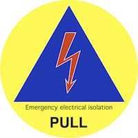
1.26 Instrumentation ...............................................................................................................20

     1.27 Automatic functions .........................................................................................................21

     1.28 Electrical safety .................................................................................................................21

     1.29 Electrical safe state .......................................................................................................... 22

2.      Cruiser class .......................................................................................................................... 24

3.      Adventure class.....................................................................................................................26

4.      Sustainability / Electric Vehicle Class: ..................................................................................26

Glossary ........................................................................................................................................ 27

                                                                                                                                                  2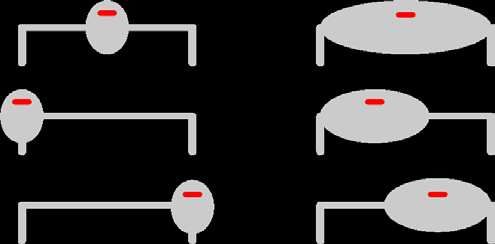
1. Solar car regulations
1.1     Classes
1.1.1   The 2020 Sasol Solar Challenge will have three classes of solar car:

        •   Challenger class is for single-seat solar cars designed to be fast

        •   Cruiser class is for efficient, practical solar cars with two or more seats

        •   Adventure class is for solar cars designed to participate in previous events but not
            eligible for Challenger or Cruiser class. Adventure class is non-competitive.

        •   Sustainability / Electric Vehicle class is for vehicles that do not fall into the
            Challenger / Cruiser / Adventure class. This is for any vehicle that is fully electric,
            powered by either solar energy or by a rechargeable battery, or hybrids. These
            vehicles must be roadworthy and must be allowed on South African roads.

1.2     Dimensions
1.2.1   When driving in a straight line, the solar car must fit inside a right rectangular prism
        5000 mm long, 2200 mm wide and 1600 mm high, with the base of the prism
        coincident with the ground.

1.2.2   The eyes of every occupant must be more than 700 mm above the ground.

1.2.3   The fully-laden solar car must be able to drive off a road with a 50mm vertical edge
        drop without any part of the solar car, other that the tyres, touching the ground.

1.2.4   For compatibility with other International Solarcar Federation (ISF) events, solar cars
        must include internal space large enough to carry supplementary solar collectors with
        a total collection area that is half of the maximum allowable area of a main solar
        collector. Supplementary solar collectors will not be allowed in the 2020 Sasol Solar
        Challenge; teams do not have to build or carry supplementary solar collectors.

1.3     Wheels
1.3.1   Challenger and Cruiser solar cars must be supported by four wheels: two front wheels
        and two rear wheels. Points of contact between the tyres and the road must be
        symmetrical about the longitudinal centreline of the solar car.

1.3.2   For Challenger and Cruiser solar cars, the distance between the front tyre centres and
        the distance between the rear tyre centres must each be more than half the width of
        the solar car.

1.4     Solar collector
1.4.1   The primary energy source for a solar car is solar irradiation collected by the solar car.

                                                                                                 3
1.4.2 A standard solar collector uses photovoltaic cells without reflectors or concentrators.
Teams wanting to use reflectors, concentrators or some other form of solar collector
must send details of the proposed solar collector to the event organiser for approval.
The power generated by a proposed non-standard solar collector should be equivalent to the power
generated from a standard solar collector.
1.4.3 If the solar collector comprises photovoltaic cells all of the same chemistry, and used
without concentrators such as reflectors or lenses, then the total cell area must not
exceed the allowable total cell area:
Class PV Cell Chemistry Allowable Total Cell Area (m²)
Allowable total cell
Class PV cell chemistry
area (m2)
Challenger Si 4.000
thin film single junction 3.560
thin film multijunction 3.240
multijunction 2.640
Cruiser Si 5.000
thin film single junction 4.440
thin film multijunction 4.050
multijunction 3.300
1.4.4 Teams must provide calculations that demonstrate compliance.
1.4.5 Cell area calculations must be based on flat, unconnected cells. For cells used without
overlapping, cell area is defined as the projected area of the cell in a direction
perpendicular to the plane of the cell. For cells that are overlapped, cell area is defined
as the exposed surface area of the cell. Cell area includes active material, busbars,
fingers and connection pads.
Example calculation: The area of a SunPower cell with a width of 125 mm and a diagonal diameter of
160 mm is less than 0.015333 m2, and so the area of 260 cells is less than 3.9866 m2 and the area of 326
cells is less than 4.9986 m2.
1.4.6 Teams wanting to use a mixture of photovoltaic cell chemistries must send details to
the organiser for approval. If the areas of the different chemistries are area A1 of
silicon cells, area A2 of thin film single junction cells, area A3 of thin film multijunction
cells and area A4 of multijunction cells then the areas must satisfy
A1 / 4.000 + A2 / 3.560 + A3 / 3.240 + A4 / 2.640 ≤ 1
for Challenger solar cars, and
A1 / 5.000 + A2 / 4.440 + A3 / 4.050 + A4 / 3.300 ≤ 1
for Cruiser solar cars.
1.4.7 If the solar collectors comprises photovoltaic cells used with concentrators such as
reflectors or lenses then the total aperture area of the solar collector must not exceed
4the allowable total cell area, by cell chemistry, for non-concentrator photovoltaic solar
collectors. Teams wishing to use concentrator photovoltaic solar collectors must
contact the event organiser for more information.
1.4.8 All devices used for solar charging must be carried in the solar car. This includes
stands, supports and cables.
1.5 Energy storage
1.5.1 A solar car may store energy. A standard energy storage system uses rechargeable
electrochemical cells. Teams wanting to use some other form of energy storage must
send details of the proposed energy storage system to the event organiser for
approval.
1.5.2 If the energy storage system comprises rechargeable electrochemical cells all with the
same chemistry, then the allowable total cell mass for Challenger and Adventure solar
cars is:
Electrochemical Cell Chemistry Allowable Total Cell Mass (kg)
Electrochemical cell chemistry Allowable total cell mass (kg)
Li-S 15.00
Li-ion 20.00
Li-polymer 20.00
LiFePO4 40.00
The allowable total cell mass of rechargeable electrochemical cells is not restricted for Cruiser solar cars.
However, the external energy used by a Cruiser class solar car, including the energy stored at the start,
will influence the team’s score.
1.5.3 Teams wanting to use other cell chemistries or a mix of cell chemistries must send
details of their proposed energy storage system to the event organiser for approval.
The Chief Energy Scientist will determine allowable configurations.
1.5.4 Li-ion cells with size designator ‘18650’ are deemed to have a cell mass of 47.6 g. The
maximum number of 18650 cells allowed for Challenger and Adventure solar cars is
420. For all other cell sizes and types, the cell mass will be deemed to be the nominal
or maximum cell mass specified in detailed cell model specifications provided by the
manufacturer.
1.5.5 Specifications from third party suppliers or found on the internet might not match
those endorsed by manufacturers. If the event organiser receives conflicting or
unclear specifications of cell mass for a particular cell model, the Chief Energy Scientist
will determine the nominal cell mass for cells of that model.
1.5.6 The sum of nominal cell masses (i.e., summed over all cells) must be not more than
the allowable total cell mass.
1.5.7 The energy storage system must be contained within at most two packs.
51.5.8 Electrochemical cells must not, at any time, be operated outside of the operating
ranges for voltage, current and temperature specified by the manufacturer. Teams
must provide manufacturer’s specifications that include:
• minimum operating cell voltage
• maximum operating cell voltage
• maximum discharge current
• maximum charge current
• maximum temperature while discharging
• minimum temperature while charging
• maximum temperature while charging.
1.5.9 Teams must provide documentation that describes how they will monitor their
electrochemical cells, and what the team and the solar car will do if any cell goes
outside specified operating limits. Teams must obtain endorsement by their certifying
engineer that an adequate and effective monitoring regime has been designed and
implemented, and fault conditions will be managed safely.
1.5.10 Batteries used only to
• power a real-time clock when the solar car is turned off; or
• retain data when the solar car is turned off; or
• power wireless tyre pressure monitors
are not considered to be part of the energy storage system, provided that the total
energy capacity does not exceed 2.0 Wh.
1.5.11 Batteries or cells inside devices such as handheld radios, cameras, mobile telephones
or wristwatches that are carried by the driver or passengers are not considered to be
part of the energy storage system, provided that they are not electrically connected
to the solar car, its instrumentation or control systems.
1.5.12 Capacitors are not considered to be part of the energy storage system if their total
energy storage capacity is less than 10.0 Wh. Such capacitors must be automatically
discharged to less than 60 V within five seconds of the solar car being placed in safe
state (see Regulation 2.29).
An external battery is not necessary to start a solar car. Possible alternatives include:
• Use a small galvanically isolated dc/dc converter inside an energy storage pack to supply voltage to
a remote start switch. You can use a separate switch on the energy storage pack to turn off this
dc/dc converter if it is not going to be used for an extended period.
• If the driver can reach the energy storage pack, put the start switch on the energy storage pack.
• Use an air switch inside an energy storage pack, with an airline to a remote start button.
61.5.13 Energy storage packs must be mounted in the solar car so that they will be restrained
in a 20g acceleration.
1.5.14 If an energy storage pack is capable of spilling dangerous liquids when damaged then
there must be a spill-proof barrier between that energy storage pack and the solar car
occupants.
1.5.15 If an energy storage pack is capable of emitting dangerous gases when damaged then
the solar car must be designed so that any gases from a damaged pack will be vented
to the exterior of the solar car behind any occupant ventilation intake.
1.5.16 Removable energy storage packs enable teams to work on their solar car while their
energy storage packs are impounded. If energy storage packs are removable then:
• each energy storage pack must remain in safe state while not connected to the
solar car
• each energy storage pack must meet the electrical safety requirements of
Section 2.28 while outside of the solar car
• the team must provide a lockable box for storing energy storage packs while they
are impounded.
1.5.17 Energy storage packs must be constructed so that each pack can be sealed using
tamper-evident plastic seals, similar to 3 × 100 mm plastic cable ties. With seals fitted,
it must not be possible to remove any cell from a pack without breaking the seal. Seals
will be provided by, and fitted by, the event organiser at scrutineering.
1.5.18 Energy storage packs must be designed and constructed so that scrutineers can verify
the cell models being used and the number of cells of each model.
1.5.19 Any charging system that is used to recharge the energy storage system (when
allowed) must meet the following requirements:
• the charger must be used with a residual current device
• the charger must be either permanently connected to the energy storage system,
or connect to the energy storage system using an appropriate connector
• the output of the charger must be electrically isolated from any ac input
• the charger must stop charging automatically when the energy storage system is
full or if a fault occurs.
1.5.20 Cruiser charging will be metered by the organiser. Cruiser solar cars must be equipped
with an on-board ac charger with an IEC 62196-2 Type 2 (male) charging inlet, and be
capable of charging from a single-phase ac supply (230 Vac, +10%, -6%). The ac current
draw must not exceed the limit indicated by the SAE J1772 pilot signal generated by
the organiser’s Electric Vehicle Supply Equipment (EVSE), which will allow charging
rates up to 30 A but may reduce the limit to as low as 6 A. The EVSE may disconnect
the car if the indicated current limit is exceeded for more than 5 seconds.
71.6 Vehicle identification
1.6.1 The solar car must have a unique Vehicle Identification Number (VIN), which must be
permanently attached to a substantial part of the solar car chassis or frame.
VINs meeting the requirements of the event can be issued by the International Solarcar Federation.
1.6.2 Solar cars must have space for mounting a rear-facing licence plate up to 220 mm wide
and up to 110 mm high. The licence plate must be mounted so that every character is
within 5 degrees of an upright position parallel to the vehicle’s axles. Every character
must be legible from every viewing position behind the solar car in the range 15° up,
0° down, 45° left and 45° right, measured from the centre of the licence plate.
If you intend to mount the licence plate inside the canopy, be aware that the trailing edge of the canopy
might obscure or distort the view of the licence plate. A mounting location will not be accepted if there
is any camera position within the designated area behind the solar car from which a photograph can be
taken where one or more of the characters is not legible. A sample licence plate graphic will be available
to registered teams from the Sasol Solar Challenge website.
1.7 Signage
1.7.1 Unbroken rectangular spaces 200 mm high and 500 mm wide must be provided on
both the left and the right sides of the solar car for event signage.
Event signage will be provided by the organiser at scrutineering. Artwork and a style guide will be
available on request. Incorrect use of artwork will result in a sticker being applied.
1.7.2 Teams must display their team number on the left and the right sides of the solar car,
in digits that are more than 150 mm high and that are clearly visible against their
background.
1.7.3 Event signage and team numbers must be completely visible from a distance of 3 m
perpendicular to the side of the solar car and at a viewing height of 1.8 m above the
ground.
1.7.4 Solar cars must have an unbroken front signage area on the solar car body forward of
the windscreen. The projection of a 600 mm × 150 mm rectangle onto the solar car
body, perpendicular to the plane of the rectangle (see the diagram below), must fit
entirely within the front signage area. The entire front signage area must be visible in
plan view and in front elevation view, and must not overlap with the solar collector. A
150 × 150 mm event logo must be placed within the projection of the rectangle, with
part of the event logo further forward than every part of the solar collector. Artwork
or a sticker for the event logo will be provided by the event organiser. The front
signage area should also include the name of the team or the name of the car.
81.7.5 The national flag of the country of entry must be displayed on the solar car, adjacent
to the windscreen. Minimum size is 70 mm × 40 mm. The flag must not be broken.
1.8 Ballast
1.8.1 Each solar car occupant will be assigned ballast so that the combined mass of the
occupant and their ballast is at least 80 kg.
1.8.2 Ballast will be supplied by the organiser in the form of steel shot packed in canvas
bags.
The approximate density of the ballast material is 5 kg per litre. Ballast provided by teams will not be
accepted.
1.8.3 The solar car must have means of securing each occupant’s ballast within 300 mm of
their hip point, in a position accessible by the observer.
1.8.4 Ballast bags must be returned to the pack-down area at the conclusion of the event.
1.9 Tracker
1.9.1 The solar car must have provision to carry a self-contained tracker provided by the
event organiser.
The box will be at most 200 mm long, 150 mm wide and 100 mm high. The upper face of the box will be
marked with a circular window with a diameter of 125 mm, as shown in the diagram. The tracker will be
self-powered. It will not require any electrical connection from the solar car. The mass of the tracker will
not exceed 5 kg. It will emit radio frequency energy with no more power than emitted by a mobile phone.
The unit will be installed during scrutineering.
91.9.2 When the tracker box is installed in the car, it must be possible to construct a right
circular cone with an apex angle of 120°, and to orient the cone so that the circular
window is entirely within the cone, and no ray from the apex and within the cone
passes through the ground or through any part of the car that is not radio-transparent
at frequencies between 300 and 3000 MHz.
1.9.3 The tracker unit will be removed at the conclusion of the event.
1.9.4 This is a standard specification for the trackers used on the Sasol Solar Challenge. Each
event/organiser may choose to supply tracking units that are smaller and lighter than
this specification. This is at the discretion of each organiser.
1.10 Safety
1.10.1 Teams are responsible for the safety and roadworthiness of their solar cars.
Compliance with the regulations and passing scrutineering does not mean that a solar
car is safe, roadworthy, and fit for purpose.
1.10.2 Each team must engage a professionally qualified engineer, responsible for inspecting
and certifying that the solar car is designed and constructed using sound engineering
practice, meets the design parameters where stated, and is roadworthy and fit for the
purpose of being driven on public roads.
1.10.3 The event organisers may, at any stage, remove a solar car from the event if they
consider the solar car or the behaviour of the team to be unsafe.
1.11 Occupant cell
1.11.1 Solar car occupants must be enclosed in an occupant cell designed to protect them
from injury.
1.11.2 Teams must provide documentation that specifies which parts of their solar car
constitute the occupant cell.
1.11.3 When occupants are seated normally, with safety-belts and helmets on, no part of any
occupant or their helmet may intersect with the convex hull of the occupant cell.
101.11.4 No point of any occupant’s helmet may lie within 50 mm of the convex hull.
Imagine stretching a rubber skin around the occupant cell; no part of any occupant may touch the skin,
and helmets must be more than 50 mm from the skin.
1.11.5 Each team must provide calculations of how the occupant cell will protect the
occupants from frontal impacts, side impacts and rollover impacts. This description
must be endorsed by the team’s certifying engineer and show that the occupant cell
will not deform by more than 25 mm and will nor fail at any point when subjected to
the following load cases, based on the fully-laden mass of the solar car.
For teams wishing to do finite element analysis of the occupant cell, the minimum test loads are:
• frontal impact: a 5 g load, opposing the direction of travel, applied to the front of the occupant cell
in an area less than 250 mm high and less than 600 mm wide
• side impact: a 5 g load into the side of the occupant cell, applied adjacent to the driver’s torso in an
area less than 250 mm high and less than 600 mm wide
• top impact: a load with components 5 g down, 1.5 g sideways and 4 g backwards, applied at each
possible area of contact between the occupant cell and the ground when the occupant cell is upside
down; the contact area for each test load must have a diameter less than 150 mm.
To reduce the risk of injury from impacts, the interior of the occupant cell adjacent to each occupant’s
pelvis, abdomen, thorax and shoulder should be covered with energy absorbing material at least 50 mm
thick and with a compressive strength of 500–1000 kPa.
1.11.6 The solar car body and occupant cell must be designed so that parts, such as the solar
collector, cannot detach and injure occupants.
1.12 Seats
1.12.1 Cruiser solar cars must be designed to carry more than one occupant.
1.12.2 Each solar car occupant must have a seat that faces forward at an angle less than 10°,
about a vertical axis, from the forward direction of travel.
1.12.3 Each seat must have a back and a head restraint. Each head restraint must be entirely
behind the occupant’s head. The distance from the hip point to the top of the head
restraint must be at least 800 mm for front seats and at least 750 mm for rear seats
11(UNECE Regulations 17 and 25). The hip point may be approximated as shown in the
diagram below.
1.12.4 Each occupant’s heels must be below their hip point.
1.12.5 The angle between each occupant’s shoulders, hips and knees must be more than 90°.
1.12.6 No more than four solar car seats may be occupied while driving.
1.13 Occupant space
1.13.1 Occupant space for each seat must comply with Act 93 of 1996: National Road Traffic
Act., As shown in the following diagram, the 835mm radius arm must be able to move
45° forwards, 25° backwards and 7° either side of vertical. The solar car structure,
including the windscreen, must lie wholly outside the occupant space. The steering
wheel, mirrors, seat backs and head restraints may be inside the occupant space, but
must be designed to minimise the risk of injury in a crash.
This minimum occupant space requirement is based on a 50-percentile male and does not allow for a
helmet. Taller team members may need more occupant space.
121.14 Safety-belts
1.14.1 Safety-belts must be fitted for each seating position. Safety-belts must be compliant
with at least one of the following standards: UNECE Regulation 16, US FMVSS 571.209,
SFI 16.1, SFI 16.5, FAI 8853/98, FAI 8854/98.
The occupant cell will provide the greatest protection when occupants are secured into the cell with four-
point or five-point harnesses.
1.14.2 Safety-belts must be fitted and used according to the manufacturer’s instructions.
1.14.3 Safety-belt anchorages must meet the intent of UNECE Regulation 14. In particular:
• upper anchorages for each seat must withstand a force of 13.5 kN applied to the
upper safety-belt straps
• lower anchorages for each seat must withstand a force of 13.5 kN applied to the
lower safety-belt straps
13• the location of anchor points must comply with the instructions of the safety-belt
manufacturer, or with UNECE Regulation 14 Annex 3.
1.14.4 Compliance must be confirmed by the team’s certifying engineer.
1.15 Egress
1.15.1 Teams must demonstrate that all occupants can exit the solar car in less than
15 seconds, without assistance. Cruiser solar cars with more than four seats will be
tested with four occupants.
1.15.2 Doors and canopies must be capable of being secured and released from inside the
solar car and from outside the solar car.
1.15.3 Emergency openings, and the methods of opening, must be clearly indicated on the
exterior of the solar car, and be visible to an emergency services first responder.
1.15.4 Except in an emergency, occupants must exit the solar car without assistance during
the event.
1.16 Cooling and hydration
1.16.1 Each solar car occupant must be provided with ventilation or cooling sufficient to
ensure that they will not overheat. The team must describe the system and have it
approved by their certifying engineer.
1.16.2 Each solar car occupant must have at least two litres of drinking water in the solar car
at the beginning of each day and when departing each control stop.
1.17 Forward and sideward vision
1.17.1 Each driver, when seated in the normal driving position with safety-belt and helmet
on, must be able to identify 75 mm high letters at every point of forward travel that
is:
• 4m from the driver’s eyes, and
• between 0.4m below eye level and 0.7m above eye level, and
• between 100° left and 100° right of the direction of travel.
142.17.2 Forward and sideward vision must be achieved without the aid of mirrors, lenses or
electronic vision systems.
2.17.3 The windscreen that is used for forward and sidewards vision must have an optical
transmittance more than 75%.
2.17.4 Traffic light colours must be discernible through the windscreen.
1.18 Rear vision
1.18.1 The solar car must have rear vision systems that enable the driver, when seated in the
normal driving position with the safety-belt fastened, to see the ground in the shaded
areas shown in the diagrams below (UNECE Regulation 46, Section 15).
151.18.2 Rear vision systems may be electronic, mirrors, or both. Rear vision systems must
operate whenever the solar car is in motion under its own power or about to be driven.
Rear vision images must be oriented so that objects on the right of the solar car are
on the right of the image.
1.19 Steering
1.19.1 Steering must be controlled by a steering wheel designed so that it cannot catch on
clothing while driving or when the driver exits the solar car.
1.19.2 Failure of any non-mechanical component of the steering system must not prevent
effective steering of the solar car.
1.19.3 Steering shafts must be designed to reduce the risk of injury to the driver in a crash.
A collapsible boss is an acceptable method to reduce steering wheel impacts.
1.20 Stability
1.20.1 Solar cars must be able to negotiate a Figure-8 course in less than 9 seconds per side
and less than 18 seconds overall.
1.20.2 Solar cars must be able to negotiate a slalom course in less than 11.5 seconds.
161.20.3 The solar car must be stable at all achievable speeds and in crosswinds.
Wind gusts exceeding 100 km/h are possible.
1.21 Brakes
Braking requirements are based on UNECE Regulation 13-H.
1.21.1 The braking system must be approved by the team’s certifying engineer.
1.21.2 The solar car must be equipped with independent primary and secondary braking
systems, so that if the primary system fails the secondary system can still stop the
solar car. The primary and secondary braking systems must each apply mechanical
braking effort to the road wheels.
Conventional cars have a brake pedal that operates two hydraulic master cylinders or one dual-chamber
master cylinder. Each master cylinder operates callipers on a pair of wheels: either the front pair and the
rear pair, or diagonal pairs. These arrangements meet the requirements for independent service and
secondary braking systems—the service system is all four wheels, and the secondary system is one pair
of wheels.
1.21.3 Independent braking systems may share components deemed ‘not liable to failure’
provided that they are amply dimensioned and readily accessible for maintenance.
Components ‘not liable to failure’ are:
• a brake pedal and its bearing
• hydraulic cylinders and their pistons
• hydraulic control valves
• brake cylinders and their pistons
• brake lever and cam assemblies.
1.21.4 Hydraulic brake hoses and lines are regarded as liable to failure.
1.21.5 For Challenger and Cruiser class vehicles, the primary braking system must apply
mechanical braking effort to all road wheels.
1.21.6 Braking must not cause the solar car to yaw. This requirement applies to both the
primary braking system and the secondary braking system.
1.21.7 For solar cars without anti-lock brakes, the front wheels must lock up before the rear
wheels.
171.21.8 The primary braking system must be able to stop the fully laden solar car within
distance
0.1 v + 0.0060 v2
metres from any speed v, in km/h, that the solar car can achieve.
1.21.9 If the primary braking system fails, the secondary braking system must be able stop
the fully laden solar car within distance
0.1 v + 0.0158 v2
metres from any speed v, in km/h, that the solar car can achieve.
1.21.10 Solar cars must be equipped with a parking brake that can be operated by the driver
from the normal driving position. The parking brake must be capable of holding the
fully-laden solar car on a 20% incline or decline.
1.22 Tyres
1.22.1 Tyres must be suitable for highway use and used in accordance with their
manufacturer’s recommendations at all times.
1.22.2 Solar cars must be fitted with tyres that are:
• compliant with UNECE Regulation 30, UNECE Regulation 75 or US FMVSS 571.109,
as indicated by an E or DOT approval marking on the tyre; or
• otherwise approved by the event organiser.
Experimental or prototype tyres must be approved by the South African road traffic authorities. The
event organiser will administer this process, which requires the tyre manufacturer to submit a sample
tyre and written technical specifications to the event organiser’s office not later than 31 May 2020. A
positive outcome to the approval process, which may take up to three months, is not guaranteed.
1.22.3 The speed rating of the tyres must be more than the maximum speed of the solar car.
The load rating of each tyre must be more than the maximum static load imposed on
it by the fully-laden solar car.
1.22.4 Tyres must be approved by the certifying engineer.
1.22.5 Tyres must be free of any apparent defect.
1.23 Reversing
1.23.1 Solar cars must be able to be driven backwards under their own power with the driver
seated in the normal position.
1.24 Lighting
1.24.1 Solar cars must be fitted with:
18• two rear stop lamps
• one central stop lamp
• left and right front direction indicator lamps
• left and right-side direction indicator lamps
• left and right rear direction indicator lamps.
1.24.2 Stop lamps must emit red light. Direction indicator lamps must emit amber light.
1.24.3 Lamps must be compliant with UNECE Regulations 6, 7 and 37, or the SAE/DOT
equivalents. Teams must demonstrate compliance by either:
• the presence of compliance markings on the lamps, or
• detailed documentation that demonstrates compliance with the photometric
requirements of the UNECE or SAE/DOT regulations, confirmed by the certifying
engineer.
Lamps approved for motorcycles may not meet these requirements.
1.24.4 Solar cars must have the correct type of lamp in each position. For example, side
marker lamps may not be used as stop lamps. Lamps must be mounted with the
correct orientation so that the photometric requirements of UNECE Regulations 6, 7
and 37, or the SAE/DOT equivalents, are met.
Lamp position and visibility requirements are based on UNECE Regulation 48.
1.24.5 Rear stop lamps must be within 400 mm of the extreme outer edge of the solar car on
each side, at least 600 mm apart (at least 400 mm apart if the solar car is less than
1300 mm wide), and at least 350 mm above the ground. The entire apparent surface
must be visible 15° up, 5° down and 45° to the left and right.
The “apparent surface” of a lamp includes all parts of the lamp surface that emit light and are not
obscured by other parts of the light-emitting surface.
1.24.6 A central stop lamp is required. Viewed from behind the solar car, the lateral position
of the lamp must coincide with the visual centre of the solar car (see the examples in
the following diagram). The lamp must be higher than a point 150 mm below the rear
windscreen or canopy, and the bottom of the lamp must be higher than the top of the
rear stop lamps. The entire apparent surface must be visible 10° up, 5° down and 10°
to the left and right.
191.24.7 Front and rear direction indicator lamps must be within 400 mm of the extreme outer
edge of the solar car on each side, at least 600 mm apart (at least 400 mm apart if the
solar car is less than 1300 mm wide), and at least 350 mm above the ground.
1.24.8 Side direction indicator lamps must be less than 1800 mm behind the front most part
of the solar car and within 400 mm of the extreme outer edge of the solar car on each
side.
1.24.9 The entire apparent surface of direction indicator lamps must be visible 15° up and 5°
down. Minimum horizontal visibility requirements (of the right direction indicator
lamps) are shown in the following diagram.
1.24.10 Direction indicators must flash at 90±30 flashes per minute.
1.24.11 It must be possible to flash the left and right direction indicator lamps simultaneously,
as a hazard warning signal.
1.25 Audible warning device
1.25.1 An audible warning device complying with the intent of UNECE Regulation 28 must be
fitted to the solar car.
1.25.2 Sound pressure level must be more than LA = 105 dB measured 2 m from the horn.
The horn should be mounted so that solar car occupants are not subjected to excessive sound pressure
levels.
1.25.3 The device must emit a continuous and uniform sound.
1.26 Instrumentation
1.26.1 The following information must be provided to the driver at all times while driving:
• the speed of the solar car
• whether the direction indicators are operating
20• whether the hazard lights are operating
• energy storage system warnings
• electronic rear vision images (if fitted).
1.26.2 This instrumentation must be powered from the energy storage system, and not from
separate batteries.
1.27 Automatic functions
1.27.1 Any cruise control function must automatically deactivate when the brake is operated
or the car is turned off.
1.27.2 Any automatic driving function must immediately deactivate on manual input or when
the car is turned off.
1.28 Electrical safety
Electrical safety requirements are based on Section 5 of UNECE Regulation 100. The term ‘high voltage’
means more than 60 V dc or more than 30 V rms ac.
1.28.1 Protection against direct contact with high-voltage parts, including conductors, must
be achieved using double insulation, enclosures or barriers. It must not be possible to
remove protection without the use of tools.
1.28.2 Protection against direct contact with high-voltage parts inside the driver, passenger
and luggage compartments must be designed to exclude objects larger than 1 mm
diameter (Ingress Protection rating IPXXD).
1.28.3 Protection against direct contact with high-voltage parts inside areas other than the
driver, passenger and luggage compartments must be designed to exclude fingers
(Ingress Protection rating IPXXB).
1.28.4 Double insulation must meet the AS 3001/IEEE 100 definition: comprising both basic
insulation and independent supplementary insulation that provides protection
equivalent to that of the basic insulation. A single layer of reinforced insulation is also
acceptable if it provides protection equivalent to double insulation.
Electrical tape wrapped around an insulated wire is not acceptable – anything damaging the electrical
tape is likely to damage the insulation too. The front surface of a photovoltaic cell is deemed to be double-
insulated if properly encapsulated.
1.28.5 High-voltage energy storage packs must be marked with the high-voltage symbol
shown in the following diagram.
211.28.6 The high-voltage symbol must also be visible on any enclosure or barrier that can be
accessed without using tools, if removing the enclosure or barrier exposes high-
voltage parts.
Example: A motor controller contains high voltage parts, so these parts must be protected by an
enclosure or barrier that requires tools to remove (Regulation 2.28.1). If it is possible to access the motor
controller enclosure without using tools (e.g. by opening the boot or tilting the solar collector) then the
motor controller enclosure must have a high-voltage symbol on it.
1.28.7 The resistance between any exposed conductive part and each terminal of the energy
storage system must exceed 100 V ohms, where V is the nominal voltage of the energy
storage system.
This is equivalent to a maximum leakage current of 10 mA.
1.28.8 The resistance between any exposed conductive part and each terminal of every solar
cell must exceed 100 V ohms, where V is the maximum circuit voltage of the solar
collector.
1.28.9 Exposed carbon fibre is considered to be an exposed conductive part and so must be
isolated from the energy storage system and from the solar collector.
1.28.10 Each energy storage pack must be protected by a fuse or circuit-breaker rated to
interrupt the short-circuit fault current of the pack. This fuse or circuit-breaker must
be mounted in or on the energy storage pack.
1.29 Electrical safe state
1.29.1 The solar car must have a ‘safe state’ which, in an emergency, minimises the risk of
electrical fire and electric shock to occupants, team members, emergency response
personnel, and bystanders. When in the safe state:
• there must not be a high voltage across any pair of conductors emerging from the
energy storage packs or from the solar collector.
• every conductor emerging from each energy storage pack must be galvanically
isolated from every energy storage cell
• voltage exceeding 15 V must not be present across any pair of conductors
emerging from energy storage packs or the solar collector, and no pair of
conductors shall be capable of delivering more than 50 mA.
1.29.2 Any conductor that is more than 200 mm from the nearest PV cell or from an
associated electronics module such as a maximum power point tracker is considered
to be outside of the solar collector.
1.29.3 All mechanisms for placing the solar car into safe state and maintaining safe state
must be fail-safe; if an electrical activation mechanism fails, the solar car must
automatically and immediately place itself into safe state, and must remain in safe
state indefinitely.
A simple design might use normally-open contactors in the energy storage packs, and have these
contactors energised via a series loop of mechanical switches, all of which must be closed for normal
22solar car operation. If the loop breaks or any switch opens, the contactors will open and the vehicle will
enter safe state.
Teams using other mechanisms, such as those incorporating solid state switches (which can fail closed)
or software (which can fail in many ways), must be able to demonstrate that the probability of the
mechanism failing to place the car into safe state is less than that of a system with normally-open
contactors and normally-closed switches.
1.29.4 The driver must be able to place the solar car into safe state while seated in the normal
driving position and without releasing the safety-belt.
1.29.5 For emergency use, an activation device that immediately places the solar car into safe
state must be provided on the exterior of the car. The activation device must be placed
within a yellow disc with a minimum diameter of 180 mm. Also in the yellow disk must
be a blue equilateral triangle (minimum side length 150 mm) that contains a red flash,
with the legend Emergency Electrical Isolation. In addition, there must be a clear
instruction on how to operate the device (e.g., PULL or PRESS). The yellow isolation
disc and the activation mechanism must be clearly visible to an emergency services
first responder approaching the driver, and must be within 100 mm of the base of that
part of the windscreen used to meet the forward vision requirement, and adjacent to
the driver egress opening.
232. Cruiser class
2.4.1 The goal for Cruiser teams is to design and build a practical solar car, and transport
people from Pretoria to Cape Town, via Uitenhage. Cruiser teams will be scored on
energy efficiency, practicality and distance.
2.4.2 Cruiser teams must arrive at daily end locations prior to the closing of Parc Fermé
(17:00).
2.4.3 Teams arriving at a staging location after the specified latest arrival time will be
deemed to a penalty that will be determined by the Clerk of the Course. These
penalties could be time or km’s penalties, and will be served out within 12 – 24 hours
of the infringement.
2.4.4 Teams arriving at the daily finish line, (after the 10min Grace period) will have their
score reduced by 1 percent for each minute late.
2.4.5 Cruiser solar cars may be recharged from Electric Vehicle Supply Equipment (EVSE)
provided by the organiser between sunset and sunrise. No other charging from
external sources is allowed. The external energy used to recharge the solar car will be
measured by the organisers. The time each Cruiser teams spends charging from
external sources will be published, along with the energy used, and will be considered
by the practicality judges.
2.4.6 Each Cruiser solar car completing at least the first stage will be given a final score
calculated by
S = D / E × P × 0.99(l + d)
where
• D is the person-km distance travelled ( x )
• E is the nominal external energy use of the solar car, in kilowatt-hours
• P is the practicality score of the solar car, between 0 and 1
• l is the total lateness at each day, in minutes (in excess of 10)
• d is the number of demerit points received by the team.
2.4.7 The Cruiser Cup will be awarded to the Cruiser team that completes at least 1’200km
with the highest score.
2.4.8 Cruiser class teams arriving at the Cape Town marshalling point after 15:00 on day 8
will have their score reduced by 1 percent for each minute late.
2.4.9 The progressive score of a Cruiser team at the end of each day will be calculated by
S = D / E × 0.99(l + d)
24where
• D is the person-km distance travelled between day start and the control stop
• E is the nominal external energy use of the solar car, in kilowatt-hours, prior to
arriving at the control stop
• l is the total lateness at at the day end, in minutes (minus the 10 minutes grace,
excluding the last day, where there is no grace)
• d is the number of demerit points received by the team.
2.4.10 Nominal external energy use of a Cruiser solar car will be calculated as E0 + Σ En, where
E0 is the nominal energy capacity of the energy storage system, En is the sum of all
recharge energy measured at each of the charging points provided by the organisers.
The nominal energy capacity of a rechargeable electrochemical battery is the sum of
the nominal cell masses in kilograms multiplied by:
• 330 Wh kg-1 for Li-S cells
• 250 Wh kg-1 for Li-ion cells
• 250 Wh kg-1 for Li-polymer cells
• 125 Wh kg-1 for LiFePO4 cells.
2.4.11 The nominal energy capacity of other types of energy storage system will be
determined by the Chief Energy Scientist.
2.4.12 Person-kilometre distance is the sum of the distances travelled by drivers and
passengers in the solar car. Person-kilometres will be counted for each seat that is
occupied for a complete leg between consecutive control stops.
2.4.13 The practicality score for a Cruiser team will be determined by a panel of judges
appointed by the organiser. Each judge will allocate a single score, between 0 and
100%, to each team. The final practicality score for a team will be the arithmetic mean
of the individual judge’s scores. Judges will be asked to consider:
• design innovation
• environmental impact
• ease of access and egress
• occupant space and comfort
• ease of operation (driving and charging)
• versatility
• style and desirability
• suitability for the declared purpose.
• advanced safety considerations
25Judges will not be told how much weight to place on each of these criteria.
The number of seats will not contribute to the practicality score, because the benefits of more seats
should be reflected in the person-km score.
2.4.14 Cruiser teams must prepare a brochure that describes their car, how it will be used,
and how it will interact with a smart grid. Teams must also give a 3-minute
presentation about their car to the judges in Cape Town, and allow judges to get into
their car to test the space and comfort.
3. Adventure class
3.1.1 Adventure class is non-competitive.
3.1.2 Teams in Adventure class will not be ranked by performance.
3.1.3 Adventure class vehicles must have competed before in a Solar Challenge (WSC, SSC,
ASC, JSC), in the primary competitive class (i.e. Other than the Adventure Class)
4. Sustainability / Electric Vehicle
Class:
4.1.1 Sustainability / Electric Vehicle Class is non-competitive.
4.1.2 Vehicles that fall into this class must me roadworthy and vehicles that are allowed on
South African roads. These vehicles are subject to approval by the Clerk of the Course.
4.1.3 Sustainability / Electric Vehicle class is for vehicles that do not fall into the Challenger /
Cruiser / Adventure class. This is for any vehicle that is fully electric, powered by either
solar energy or by a rechargeable battery, or hybrids.
4.1.4 Vehicles will be awarded prises on their particular design criteria or by their
performance in activities set by the awards committee. This committee will have the
final say in all awards.
4.1.5 This is a demonstration opportunity for EV’s and manufacturers, activities will be
designed to meet this objective.
26Glossary
Battery Electrochemical cells wired in series or parallel and housed in
a single container.
CB Citizen’s Band radio.
Certifying Engineer A professional engineer engaged by a team to report on
compliance with regulations and roadworthiness
requirements.
Clerk of the Course The person responsible for coordinating Dynamic
Scrutineering and the on-road portion of the event.
DOT United States Department of Transport.
DST South African Department of Science and Technology.
Energy Storage Pack A self-contained box containing components of the energy
storage system, such as electrochemical cells and a battery
management system.
Energy Storage System The solar car subsystem used to store energy. It is typically a
rechargeable electrochemical battery, but other types of
energy storage system are possible.
Entrant The legal entity that completes the Participation Agreement
and requests a place in the event for one or more teams. An
entrant is typically a registered institution, organisation or
commercial entity.
Event Name The official name of the event is the “2020 Sasol Solar
Challenge”.
BWSC Bridgestone World Solar Challenge.
EVSE Electric Vehicle Supply Equipment.
FAI Federation Internationale de l’Automobile.
FMVSS United States Federal Motor Vehicle Safety Standards.
27High Voltage More than 60 V dc or more than 30 V rms ac.
ISF International Solarcar Federation.
Judge A person invited to make subjective comment on Cruiser Class
attributes.
Judge of Fact A person recognised by the organiser as able to determine
whether a particular event occurred (e.g. whether a team
obstructed traffic).
Participant A person who has registered to participate in the event as a
member of a team.
PV Photovoltaic.
Road-Ready Ready to drive on the road.
Official Website http://www.solarchallenge.org.za
Official Instagram http://www.
Official Facebook http://www.facebook.com/SASolarChallenge
Official Twitter http:twitter.com/_Solar_Challenge
Official Time South African Standard Time GTM +2. This is given on the
South African telephone number 1026.
Scrutineering The process of checking the solar car and other team vehicles
for compliance with the regulations.
SFI The SFI Foundation issues standards for motor sports
equipment.
Solar Collector The solar car subsystem used to collect solar energy. It is
typically an array of photovoltaic cells, with or without
concentrators or reflectors, but other types of solar collector
are possible.
28Steward An event official responsible for ensuring regulations are
applied correctly and fairly.
Team A group of people registered by the entrant to participate in
the event. An entrant may have more than one team
participating in the event.
Team Manager The person in charge of, and responsible for, the actions of a
team.
UHF Ultra-High Frequency. Commonly refers to South African two-
way radio..
UNECE United Nations Economic Commission for Europe, responsible
for regulations for motor vehicles.
UTC Coordinated Universal Time.
VIN Vehicle Identification Number.
29You can also read