Communication with a Toyota Prius - Semester-Project
←
→
Page content transcription
If your browser does not render page correctly, please read the page content below
Autonomous Systems Lab
                                                            Prof. Roland Siegwart

                           Semester-Project

                   Communication with a
                      Toyota Prius

                   Decoding of the CAN Protocol and
                  Development of a Graphical Interface

                           Autumn Term 2009

Supervised by:                                            Authors:
Jérôme Maye                                             Mario Krucker
Rudolph Triebel                                           Raphael Bitzi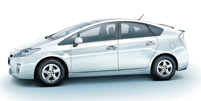
Contents

List of Tables                                                                                                   iii

List of Figures                                                                                                   v

Abstract                                                                                                         vii

Symbols                                                                                                          ix

1 Introduction                                                                                                    1

2 Related Work                                                                                                    3
  2.1 My CAN Project . . . . . . . . . . . . . . . . . . . . . . . . . . . . .                                    3
  2.2 Team-LUX . . . . . . . . . . . . . . . . . . . . . . . . . . . . . . . .                                    3
  2.3 SmartTer . . . . . . . . . . . . . . . . . . . . . . . . . . . . . . . . .                                  4

3 Toyota Prius - Background                                                                                       7
  3.1 Hybrid Synergy Drive . . . . . . . . . . .     .   .   .   .   .   .   .   .   .   .   .   .   .   .   .    7
      3.1.1 Functionality . . . . . . . . . . . .    .   .   .   .   .   .   .   .   .   .   .   .   .   .   .    8
      3.1.2 Hybrid Vehicle Control System . .        .   .   .   .   .   .   .   .   .   .   .   .   .   .   .   10
  3.2 Controller Area Network . . . . . . . . . .    .   .   .   .   .   .   .   .   .   .   .   .   .   .   .   11
      3.2.1 Multiplex-Communication Systems          .   .   .   .   .   .   .   .   .   .   .   .   .   .   .   11
      3.2.2 CAN Protocol . . . . . . . . . . .       .   .   .   .   .   .   .   .   .   .   .   .   .   .   .   12
  3.3 CAN in the Prius . . . . . . . . . . . . . .   .   .   .   .   .   .   .   .   .   .   .   .   .   .   .   13

4 Methodology                                                                                                    17
  4.1 Connection to the CAN . . . . . . . . . . . . . . . . . . . . . . . . .                                    17
  4.2 Messages Analysis . . . . . . . . . . . . . . . . . . . . . . . . . . . .                                  17
  4.3 Control Actuators . . . . . . . . . . . . . . . . . . . . . . . . . . . .                                  20

5 Results                                                                                                        23
  5.1 Results of Messages Analysis . . . . . . . . . . . . . . . . . . . . . .                                   23
  5.2 Results of Control Actuators . . . . . . . . . . . . . . . . . . . . . .                                   24

6 Conclusion and Further Work                                                                                    27

Bibliography                                                                                                     29

                                          i
ii
List of Tables

 3.1   Properties of the Prius MPXs. . . . . . . . . . . . . . . . . . . . . .     11
 3.2   Base frame format . . . . . . . . . . . . . . . . . . . . . . . . . . . .   13

 5.1   ID and content of CAN messages. . . . . . . . . . . . . . . . . . . . .     23

                                        iii
iv
List of Figures

 2.1   Side view of the SmartTer . . . . . . . . . . . . . . . . . . . . . . . .                           4
 2.2   SmartTer steer-by-wire system diagram. . . . . . . . . . . . . . . . .                              5

 3.1   Toyota Prius NHW20 side view. . . . . . . . . .     .   .   .   .   .   .   .   .   .   .   .   .    7
 3.2   Toyota Hybrid Synergy Drive logo. . . . . . . .     .   .   .   .   .   .   .   .   .   .   .   .    8
 3.3   Simplified cross section of the hybrid transaxle.   .   .   .   .   .   .   .   .   .   .   .   .    9
 3.4   Diagram of the HSD communication system. .          .   .   .   .   .   .   .   .   .   .   .   .   10
 3.5   Diagram of a CAN . . . . . . . . . . . . . . . .    .   .   .   .   .   .   .   .   .   .   .   .   12
 3.6   Schema of the Prius CAN bus. . . . . . . . . .      .   .   .   .   .   .   .   .   .   .   .   .   14
 3.7   Location of CAN components. . . . . . . . . . .     .   .   .   .   .   .   .   .   .   .   .   .   15

 4.1   CPC-USB device. . . . . . . . . . . . . . . . . . . . . .           .   .   .   .   .   .   .   .   17
 4.2   Connection between laptop and DLC3 port. . . . . . .                .   .   .   .   .   .   .   .   18
 4.3   Example of the monitoring tool. . . . . . . . . . . . .             .   .   .   .   .   .   .   .   19
 4.4   Course of the steering angle value of 0x25 and 0x264.               .   .   .   .   .   .   .   .   21

 5.1   GUI displaying several states of the Prius. . . . . . . . . . . . . . .                         .   24
 5.2   CAN diagram of EPS. . . . . . . . . . . . . . . . . . . . . . . . . .                           .   25
 5.3   CAN diagram of the gearshift. . . . . . . . . . . . . . . . . . . . .                           .   25
 5.4   CAN diagram of the signal from the gaspedal to the throttle valve.                              .   26

                                        v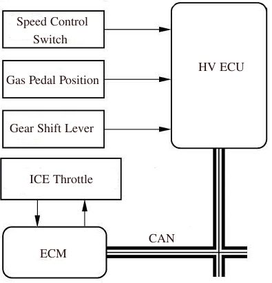
vi
Abstract

In the context of autonomous car navigation, the Autonomous System Lab (ASL)
of the ETH Zurich is willing to build a new research platform. For this purpose,
a Toyota Prius has been bought. The first required step to turn the Prius into an
autonomous car is to have an electronic access to its low-level functions such as the
steering, the brakes, the gas and the gear. This report is focused on analyzing the
feasibility to display and control car states via the vehicle’s CAN bus.
The interface with the CAN bus was achieved by a CPC-USB device connected
with a RS232 connector to the DLC3 diagnostic port of the CAN-Bus. In a first
step, existing CAN-Messages has been identified and their content interpreted. Also
their reliability has been investigated. It turned out that the RS232 port has a lower
transfer rate than the CAN bus. Thus, the frequency of the received messages was
not constant. Based on the knowledge of the existing messages we duplicated and
modified the messages and sent them onto the CAN bus in order to change the car
status. The dissatisfying results revealed that car states can not be influenced by
the CAN bus with a sufficient behavior. We were able to change the position of the
steering wheel, but other states could not be influenced by CAN messages with a
satisfying result without modifying the CAN bus.
The CAN bus may be used for displaying car states. It is advisable to connect your
system directly to the CAN bus via the connection assembly. To control car states
direct electronic links to the corresponding sensors or actuators should be used in
order to achieve acceptable results.

                                         vii
viii
Symbols

Symbols
δ              steering wheel angle offset
φ              steering wheel angle
bi             decimal value of the byte i

Acronyms and Abbreviations
ASL    Autonomous System Lab
CAN    Controller Area Network
ECU    Electronic Control Unit
EPS    Electric Power Steering
ETH    Eidgenoessische Technische Hochschule
HSD    Hybrid Synergy Drive
ICE    Internal Combustion Engine
IMU    Inertial Measurement Unit
ID     Identifier
IPAS   Intelligent Parking Assist System
MG1    Motor-Generator 1
MG2    Motor-Generator 2
MPX    Multiplex-Communication System
ODB    On-Board Diagnostics
SOC    State Of Charge

                                   ix
x
Chapter 1

Introduction

In the context of autonomous car navigation, the Autonomous System Lab (ASL)
of the ETH Zurich is building a new research platform based on the knowledge ac-
quired in the earlier project called SmartTer [1]. The SmartTer was equipped with
a drive-by-wire system to control the gas pedal, the brake pedal and the steering
wheel from a central computation unit. Based on that, research on autonomous
driving and mapping becomes possible.
To enable autonomous driving with the new vehicle, the Toyota Prius, it is required
to have an electronic access to its low-level functions such as the steering, braking,
acceleration and gear shifting. The aim of this report is to determine the feasibility
of displaying important sensory information and controlling the basic functions of
the car via the vehicle’s CAN. This should be done without modifying the CAN
bus and ECUs. Some car states (e.g. car speed, steering angle, etc.) can be used
as feedback signals for high-level and low-level control. Therefore, the reliability,
accuracy and precision of the sensor data provided by the CAN bus have to be ver-
ified. In a further step, messages has to be sent to the CAN bus in order to control
certain actuators of the car such that the steering, accelerating, decelerating and
gear shifting becomes possible.
In the first step, the access to the CAN bus of the vehicle has to be enabled. After-
wards, transmitted data has to be received, identified and their content converted
into useful information. On the one hand, that provides important information
about the car states. On the other hand, the comprehension of the messages pro-
vides information about the communication between the connected devices. This
is required for the next step. Once the messages, their content and their properties
are known, it is possible to send self-generated messages onto the CAN bus in order
to control car states.
This report is structured as follows. In Chapter 2 related projects are presented.
The next chapter summarizes the findings of the background investigation. It con-
tains information about the Toyota Prius and full-hybrid car technology. It also
introduces the CAN protocol and the usage of the CAN in the Toyota Prius. Chap-
ter 4 describes our procedure. It starts with connecting our computation unit to
the CAN bus, followed by analyzing received messages and sending messages onto
the CAN. Chapter 5 shows the results of this project.

                                          1
Chapter 1. Introduction 2
Chapter 2

Related Work

In order to turn the Prius into an autonomous vehicle the electronic access to the
low-level functions of the car is required. This chapter presents related projects
where vehicles are controlled with a drive-by-wire system.
The first section introduces a project that focuses on reading CAN messages of
a Toyota Prius 2004. Section 2.2 shows how a VW Passat was turned into an
autonomous car. The last section presents the SmartTer. A standard Smart car
that was modified in such a way that autonomous navigation becomes possible.

2.1     My CAN Project
Attila Vass [2] worked with an Toyota Prius 2004. This is an older version of the
Prius than we are working with. He wanted to get more information about the car
status than it was given on the standard display. He connected to the CAN via the
OBD connector with and CAN232-USB serial. Vass was able to read the following
states of the car:

   • engine speed

   • engine and coolant temperature

   • battery state of charge, voltage and temperature

   • gas gauge, throttle, speed

   • two acceleration sensors

   • rotation speeds on individual wheels

   • brake, gas pedal and steering wheel values

With an on-board computer he displayed online all the desired Prius states during
driving. He provides on his website his findings of the CAN messages. In this
project we used, verified and extended his information about the CAN messages.

2.2     Team-LUX
The autonomous car LUX was developed for the Defense Advanced Research Projects
Agency (DARPA) Urban Challenge by the sensor and laser scanner producers Ibeo
and SICK [3]. DARPA Challenges are field tests of autonomous ground vehicles
over different terrain.

                                        3
Chapter 2. Related Work 4
The LUX is a VW Passat 2.0 TDI built in 2006. The autonomous control equip-
ment is fully integrated into the vehicle (i.e. the car may be driven by a driver).
The breaking system is a servo tube, which can operate the brake pedal just like
a driver. This electromechanical braking system is controlled by an on-board com-
puter. The so-called E-Gas module is an electrical switch which is built in between
the gas pedal and the motor control device. Control commands are sent from the
main computation unit through the vehicle’s CAN bus to the respective control
units. For steering, a special motor was installed which is connected with a timing
belt to the steering column. Also commands for steering are sent via the CAN
bus and converted with 0.5 degree accuracy into a turning motion of the steering
wheel. The turning rate, the torque and the desired position can be given. Also the
electronic gear shifter can be controlled via CAN with a similar function method as
the E-Gas. An electronic switch is connected between the automatic gear shift and
the gearbox control device. During autonomous driving, the actual position of the
gear shift (P, R, N or D) does not matter.
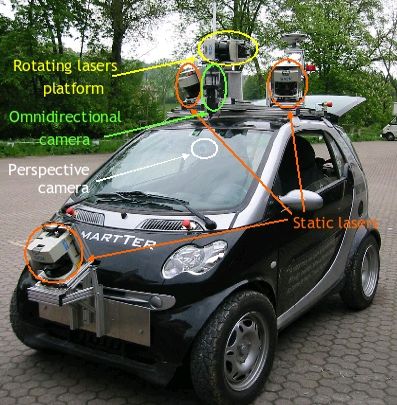
2.3 SmartTer
The SmartTer (Smart all Terrain) is the predecessor of the Toyota Prius. The
main idea of the SmartTer was to construct a hardware platform that allows to
perform the task of autonomous navigation in large scale outdoor environments. A
standard Smart car was modified in such a way that all necessary characteristics
for autonomous navigation and mapping are included.
Driving the car with a drive-by-wire system was enabled. Moreover, the car was
equipped with five distance laser sensors, two cameras, an omni directional camera,
a differential GPS, an Inertial Measurement Unit, an optical gyroscope and four
computer racks. The fully equipped SmartTer is depicted in Figure 2.1. Since the
Figure 2.1: Side view of the SmartTer [1].5 2.3. SmartTer
Smart was equipped with a power steering motor that has enough torque to steer
the car, it was possible to steer-by-wire. The smart already has a auto gearshift.
Thus, no additional modifications were required to switch gears while the car was
driving. The Smart was already equipped with a CAN bus. The vehicle CAN
bus provided important sensory informations such as the steering wheel angle and
wheel velocities. These features facilitate the process of converting such a vehicle
for autonomous driving.
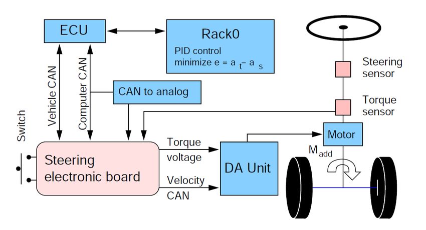
In Figure 2.2 the diagram of the steer-by-wire system is shown. For this system,
a specific electronic board has been designed. In order to use the power steering
motor of the Smart its control unit (DA unit) was disconnected from the vehicle
CAN bus and routed to a computer (Rack0). An additional CAN bus (Computer
CAN) was installed to feed the DA unit with CAN messages. The electronic board
enables the use of a computer to set the gas and the steering wheel commands.
The Computer CAN sends commands to a CAN-to-analog module which fakes the
torque voltage of the steering column torque sensor and the position voltage of the
gas pedal position sensor needed by the DA unit. A switch allows to choose between
normal or controlled mode. A servo motor was used to activate the brake pedal.
Figure 2.2: SmartTer steer-by-wire system diagram [1].Chapter 2. Related Work 6
Chapter 3

Toyota Prius - Background

During this project we were working with a Toyota Prius NHW20, model year 2006.
A picture of the car is shown in Figure 3.1. The Toyota Prius (short Prius) is a full
hybrid electric mid-size car developed and manufactured by the Japanese Toyota
Motor Corporation [4]. It first went on sale in Japan in 1997 and was the first mass-
produced hybrid vehicle. It was subsequently introduced worldwide in 2001. The
Prius is sold in more than 40 countries and regions. In May 2008, global cumulative
Prius sales reached the 1 million vehicle mark.

                 Figure 3.1: Toyota Prius NHW20 side view [10].

The first section of this chapter presents the Hybrid Synergy Drive of Toyota. Sec-
tion 3.2 gives an overview of the Controller Area Network. The usage of the CAN
bus in the Prius is described in the last section.

3.1     Hybrid Synergy Drive
The Hybrid Synergy Drive (HSD) is a set of hybrid car technologies developed by
Toyota which allows the realization of a full hybrid vehicle [5]. That allows the car
to perform on the electric motor only as opposed to other, so called mild hybrid,
cars can not. The electric motor of mild hybrid cars only supports the Internal

                                         7
Chapter 3. Toyota Prius - Background 8
Combustion Engine (ICE) with additional torque. A full hybrid vehicle combines
an electric propulsion system and a continuously variable transmission with the ICE.
The HSD is a drive-by-wire system with no direct mechanical connection between
the engine and the engine controls: both, the gas pedal and the gear shift lever send
electrical signals to a control unit.
Figure 3.2: Toyota Hybrid Synergy Drive logo [10].
In the standard car design the alternator (AC generator) and starter (DC motor) are
considered accessories that are attached to the ICE. The ICE drives a transmission
to power the wheels. A battery is used only to start the internal combustion engine
of the car and runs accessories when the engine is not running. The alternator
is used to recharge the battery when the engine is running. The HSD technology
replaces the conventional gear box, alternator and starter with:
• a pair of powerful motor-generators (MG1 and MG2) with a computerized
shunt system (HV ECU) to control them,
• a mechanical power splitter that acts as a second differential, called the hybrid
transaxle, and
• a NiMH-Battery pack that stores the energy.
Subsection 3.1.1 supplies background information about the functionality of the
HSD. In the second subsection the hybrid vehicle control system is introduced.
3.1.1 Functionality
A continuously variable transmission is the main part of the HSD [5]. A simplified
cross section of the hybrid transaxle, the mechanical gearing design of the system,
is displayed in Figure 3.3. This design allows the mechanical power from the ICE
to be split three ways:
• extra torque at the wheels (under constant rotation speed),
• extra rotation speed at the wheels (under constant torque),
• and power for an electric generator.
The Hybrid Vehicle Control Unit (HV ECU), which is presented in Subsection 3.1.2,
directs the power flow from the engine and motor sources. The hybrid transaxle
contains a planetary gear set that adjusts and blends the amount of torque from the
ICE and motor-generators as it is needed by the front wheels. MG2 and the ICE
work together to drive the wheels. MG2 is mounted on the drive shaft, the annulus,
and thus couples torque into or out of the drive shafts. So if electricity is fed into
MG2, it adds torque at the wheels. The drive shaft has a second differential: one
leg of this differential is attached to the internal combustion engine and the other
leg is attached to MG1. The differential relates the rotation speed of the wheels to
the rotation speeds of the engine and MG1. MG1 is used to absorb the difference
between wheel and engine speed by generating electrical power. This electrical9 3.1. Hybrid Synergy Drive
Figure 3.3: Simplified cross section of the hybrid transaxle [6].
power is used for recharging the NiMH-Battery pack. Special couplings and sensors
monitor rotation speed of each shaft and the total torque on the drive shafts, for
feedback to the control unit.
The HSD works by shunting electrical power between the two motor generators,
running off the battery pack, to even out the load on the ICE. Since a power boost
from the electrical motors is available for periods of rapid acceleration, the ICE
can be down sized to match only the average load on the car. Thus, the smaller
internal combustion engine can be designed to run more efficiently. Furthermore,
during normal operation the engine can be operated at or near its ideal speed and
torque level for power, economy, or emissions, with the battery pack absorbing or
supplying power as appropriate to balance the demand placed by the driver. During
traffic stops the internal combustion engine can even be turned off for even more
economy.
The HSD operates in distinct phases depending on demanded speed and torque.
Here, the most important phases of operation are listed:
• Low gear: When accelerating at low speeds in normal operation, the ICE
turns more rapidly than the wheels but does not develop sufficient torque.
The extra engine speed is fed to MG1. The output of MG1 is fed to MG2,
acting as a motor and adding torque at the drive shaft.
• High gear: When cruising at high speed, the engine turns more slowly than the
wheels but develops more torque than needed. MG2 then runs as a generator
to remove the excess engine torque, producing power that is fed to MG1 acting
as a motor to increase the wheel speed. In steady state, the engine provides
all of the power to propel the car. During heavy acceleration or driving up a
steep incline at high speed the ICE is unable to supply enough power. In this
case, the battery supplies the difference.
• Reverse gear: There is no reverse gear as in a conventional gearbox. The
HV ECU just feeds negative voltage to MG2, applying negative torque to the
wheels. If the battery is low, the system can simultaneously run the engine
and draw power from MG1.Chapter 3. Toyota Prius - Background 10
• Silent operation: At slow speeds and moderate torques the HSD can drive
without running the internal combustion engine at all. Electricity is supplied
only to MG2, allowing MG1 to rotate freely (and thus decoupling the engine
from the wheels). This is popularly known as Stealth Mode. Provided that
there is enough battery power, the car can be driven in this silent mode for
some miles even without gasoline.
• Regenerative braking: During braking the motor-generators are working in
the generator mode converting much of the forward motion into electrical
current flow which is used to recharge the batteries while slowing down the
vehicle. Harder braking action engages standard front disk and rear drum
brakes which are also provided for faster stops and emergency use.
3.1.2 Hybrid Vehicle Control System
The Hybrid Vehicle Control Unit (HV ECU) optimizes the power output and the
torque of driving forces to reduce the fuel consumption and the pollutant of the
exhaust gas [6]. The optimal required driving power of the ICE, MG1 and MG2
is based on its inputs signals which are the gas pedal position, rotation speed of
the drive shaft and gear shift lever position. Also the state of charge (SOC) of the
battery pack and the temperature of the motor-generators have influence on the
optimal driving power. Figure 3.4 shows a schematic diagram of the communication
between the HV ECU and the other HSD devices.
Figure 3.4: Diagram of the HSD communication system [6].11 3.2. Controller Area Network
3.2 Controller Area Network
Based on sensor data inputs Electronic Control Units (ECUs) control different ac-
tuators [7]. The ECUs, sensors and actuators communicate with each other through
so-called multiplex-communication systems. The Prius uses primarily three differ-
ent communication systems:
• Controller Area Network (CAN)
• Body Electronics Area Network (BEAN)
• Audio Visual Communication-Local Area Network (AVC-LAN)
The following subsection gives an overview of the three communications systems
of the Prius. Subsection 3.2.2 introduces the CAN. The last subsection shows the
usage of the CAN bus in the Toyota Prius.
3.2.1 Multiplex-Communication Systems
Multiplex-communication systems (MPXs) uses serial communication between the
connected ECUs [8]. Compared to parallel communication systems, where every
subsystems is connected separately with the other subsystems, serial communication
systems connects all ECUs through one single channel called bus. For data transfer
through these buses the information has to be converted into data frames. Table 3.1
MPX Connected Maximum Data
devices communication length
speed
[kbit/s] [bytes]
CAN EV Battery 1000 0–8
Chassis
Motor
Braking
Anti-lock Breaking System (ABS)
Steering Angle Sensor
Inertial Measurement Units (IMU)
Electric Power Steering (EPS)
Hybrid Vehicle Control System (HV)
BEAN Gearbox Control 10 0–11
Autobody (Windows, Lightning...)
Operating System
Air Conditioning System
Smartkey
Car-theft Protection
AVC- Multidisplay 17.8 0–32
LAN Navigation
Hi-Fi System
Table 3.1: Properties of the Prius MPXs [6].
gives an overview of the properties of the MPXs and which components of the Prius
they connect together. The networks are working on the same concept, but they
have different message formats, message lengths and communications speeds.
The BEAN is also called comfort bus. It contains control devices as for lightning,
windows and air conditioning system. Hence, no high communication speed isChapter 3. Toyota Prius - Background 12
required. Operation, display and navigation systems are connected through the
AVC-LAN. The CAN is responsible for the communication between the ICE and
the HSD system. This network allows a fast and secure data transfer. The three
MPXs are connected through the Gateway-ECU which allows a coupling of networks
with different architectures.
3.2.2 CAN Protocol
The Controller Area Network (CAN) was developed by the ROBERT BOSCH
GmbH [8]. Originally, it was used as a standard bus system for automobiles. To-
day, it is also used in other areas such as automation systems. The CAN is a
multi-master network which uses serial communication. Thus, every member of the
network has equal and active access to the bus, means that every member is allowed
to receive and send onto the CAN bus. The CAN bases on a protocol that supports
real-time data communication between control devices that guarantees a high level
of safety. Incomplete or incorrect messages are re-transmitted automatically.
A simple example of a CAN where three ECUs are connected trough a CAN bus
is depicted in Fiure 3.5. Each member of the CAN, called node, is able to send
messages (also known as frames) onto the CAN bus, but not simultaneously. The
message is transmitted serially on the bus and is sensed by all other nodes. If
the bus is free (no node is sending a message), any node may begin to transmit a
message. If two or more nodes begin sending at the same time, the message with
the more dominant Identifier (ID), means lower ID value, will overwrite the other
messages. Messages with a high ID value will be sent later when the bus is free.
Bit rates up to 1 M bit/s are possible in a network with a length below 40 m. Longer
network distances decreases the bit rate.
Figure 3.5: Diagram of a CAN with three members [8].
Nodes
Each node consists of a host processor, a CAN controller and a Transceiver [9].
The host processor reads messages and decide which message it want to transmit
itself. The CAN controller receives messages by storing the bits and sends the entire
message to the host computer or transits bits serially on the bus if the host processor
wants send a message. The transceiver adapts signal levels from the bus (receiving)13 3.3. CAN in the Prius
or converts the transmit-bit signal received from the CAN controller into a signal
that is sent onto the bus (sending).
Frames
Each frame is a sequence of bits which are serial transferred by the CAN bus. The
CAN can be configured to work with two different frame formats: the standard
frame format and the extended frame format [9]. The two format differs only in
their length of bits of the identifier (ID). The standard frame format, which is used
in the CAN bus of the Prius, supports a length of 11 bits and the extended frame
format supports a length of 29 bits.
In this section, only the standard frame format will be considered. The CAN pro-
tocol distinguish between four types of frame types:
• Data frame: contains node data for transmission.
• Remote frame: requests the transmission of a specific identifier.
• Error frame: transmitted by any node that detects an error.
• Overload frame: injects a delay between data and/or remote frames.
The standard frame format is described in Table 3.2. The most important fields of
CAN frames are the identifier and the data filed. The CAN protocol uses a object-
oriented addressing [8]. Thus, a transmitted message gets a network-defined ID as
its address. The nodes listens only for messages with a certain ID. The data field
contains the real information of the message.
Filed name Length Purpose
[bits]
Start-of-frame 1 Denotes the start of frame transmission
Identifier (ID) 11 Unique identifier for the data
Remote transmission 1 Dominant (0) if specific data frame is
request requested. See remote frame
Identifier extension bit 1 Dominant (0)
Reserved bit 1 Dominant (0)
Data length code 4 Number of bytes of data (0-8 bytes)
Data field 0-8 Data to be transmitted
[bytes]
CRC 15 Cyclic Redundancy Check
CRC delimiter 1 Must be recessive (1)
ACK slot 1 Transmitter sends recessive (1) and
any receiver can assert a dominant (0)
ACK delimiter 1 Must be recessive (1)
End of frame 7 Denotes the end of frame transmission
(must be recessive (1))
Table 3.2: Base frame format [9].
3.3 CAN in the Prius
As listed in Table 3.1 and shown in Figure 3.6 the Prius uses the CAN bus to
transmit informations between the battery, brake systems, steering angle sensor,
EPS (connection assembly 1), ICE control system, IMU and the hybrid control unitChapter 3. Toyota Prius - Background 14
(HV) (connection assembly 2). The location of the CAN devices are shown in Fig-
ure 3.7.
The ECUs of the Prius connected to the CAN bus do not use remote frames [11].
Therefore, all messages are sent periodically or event-oriented. The DLC3 port is
Figure 3.6: Schema of the Prius CAN bus. [6]
a serial CAN interface and is originally installed for the coupling of diagnostic de-
vices [6]. Diagnostics Trouble Codes (DTCs), which contains detected disturbances
in data exchange, are sent by the particular ECU that wants to report the error
and are stored by the ECU of the DLC3. With an Intelligent Tester II the DTCs
can be retrieved. This is usually done by car mechanics.
The described DLC3 connector has a RS232 port [8]. For this project, we were work-
ing with RS232 to USB-Converter to get access of the CAN bus. Unfortunately,
the RS232 transfer rate is limited to 51.7 kbit/s.15 3.3. CAN in the Prius
Figure 3.7: Location of CAN components. [6]Chapter 3. Toyota Prius - Background 16
Chapter 4
Methodology
There were three main tasks in this poject. First we had to connect the laptop to
the CAN bus, that is descriped in Section 4.1. In Section 4.2 is explained how we
analysed the CAN messages, identified their content and display the desired states
of the Prius. The last task was to modify some CAN messages and send them over
the CAN bus to control actuators. The results are shown in Chapter 5.
4.1 Connection to the CAN
In a first step we had to connect our laptop to the CAN bus of the Prius. For this
we used a CPC-USB device from EMS Dr. Thomas Wuensche. This device, shown
Figure 4.1: CPC-USB device.
in Figure 4.1, has on one side an USB-adapter to link with a PC and a RS232-
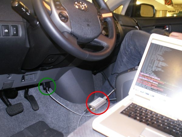
port which we connected to the On-Board Diagnostics (ODB) adapter. Figure 4.2
illustrates how we connected the laptop to the CPC-device (red circle) and then to
the diagnosis adapter (green circle). Afterwards we adapted the CAN driver form
another ASL project to our problem. So after some experiments, we were able to
receive CAN messages. In the next step we analyzed the CAN messages.
4.2 Messages Analysis
First we wanted to find out how many different CAN IDs existed, so we could
compare the IDs that we received with the list of Vass [2]. It was also of interest
to get the length of the content, i.e. number of bytes, and the frequency of every
17Chapter 4. Methodology 18
Figure 4.2: Connection between laptop and DLC3 port.
CAN ID with which we received them. So we wrote a program that stored all
CAN IDs and their length and calculated their sample frequencies. The frequency
was calculated in two different ways. On the one hand the program measured the
time to receive 500’000 CAN messages and then counted the number of received
messages with the same ID. In a second approach the program measured the time
between two CAN messages with the same ID. We observed that the elapsed time
was not constant. All the measured times between two CAN messages with the
same identifier were multiples of the smallest value. So the frequency with which
CAN messages were sent was not equal to the frequency with which we received
them. This was because of limited transfer rate of the DLC3 connector.
The next task was to understand the content of the CAN messages. We had a
small monitoring tool that displayed all the different CAN IDs with their length
and the content of the last message that was received. An example of this tool is
shown in Figure 4.3. With the information we got from Vass [2] we already had
guesses about the content of the messages. For a first approach, we choosed ten
different states that we wanted to display on a GUI. The decision which states
should be observed was influenced by three factors. For the reverse engineering it
was necessary to understand the messages of the states, that we wanted to control,
like steering angle, gear, brake and gas pedal position. We also displayed states
that easily could be checked if we write succesfully to the CAN bus, e.g. headlamp.
Third aspect was to display states that are interesting for feedback control, e.g.
velocity and engine speed.
In the following is explained how we confirmed the information from the literature
und computed the scaling coefficient by the example of the steering angle. From
the literature we expected that only the content of the message with the ID 0x25
will change. After starting the monitoring tool we turned the steering wheel. We
observed that the content of three messages changed, namely the CAN IDs 0x25,
0x262 and 0x264. We concentrated first on the CAN message with the ID 0x25.
While turning the steering wheel counterclockwise the second byte of the data field
increased to 0xF F , then it jumped back to 0x00 and the first byte increased from
0x00 to 0x01. So the first two bytes of the ID 0x25 represented the angle of the19 4.2. Messages Analysis
Figure 4.3: Example of the monitoring tool.
steering wheel. If we rotated counterclockwise by one revolution the second byte
◦
◦
increased by 0xF 0, that means that we have a resolution of 360 240 = 1.5 . When we
turned the steering wheel clockwise the value of the second byte decreased and when
the first and the second bytes were 0x00 the first jumped to 0x0F and the second
jumped to 0xF F . That means that if the value is larger then 2048 the steering
angle is negativ. The last parameter that we had to define was the offset δ from
the zero-position. We defined that at if the steering wheel is at the zero-position,
the front wheel are in a line with the rear wheel, so the car goes straight on. δ can
be positive or negative. The formula to compute the steering angle φ from the first
two bytes from the CAN message with the ID 0x25 looks as follows:
(
360
(b0 · 162 + b1 − δ) · 240 if b0 · 162 + b1 − δ < 2048
φ = 360
(4.1)
(b0 · 162 + b1 − δ − 4096) · 240 if b0 · 162 + b1 − δ ≥ 2048
Here b0 and b1 are the values of the first two bytes. We found out that the content
of the CAN ID 0x264 behaves similar, except that the offset value δ is different.
That would be enough if we just wanted to read out the states of the Prius. Since
we also want to change the states of the car we had to figure out what the other
bytes of the data field represent, because we had to be able to dublicate the whole
message. But before, we wanted to make sure that we can read out every state
and display them, so we continued with the other states. How we figured out what
the other bytes represent is descript in Section 4.3. The steering angle was easy to
discover, because the real value of the state was easy to determine. But for other
states, e.g. the acceleration sensors or the engine temperature, it is very difficult to
get the real values.
In the last step we wanted to display the values of the desired states in a GUI. We
did this by opening a second thread. One is continuously checking the incoming
CAN message if it contains useful informations, if so it stores it. The other threadChapter 4. Methodology 20
takes the values from the storage and display them in a GUI. The GUI is shown in
Figure 5.1.
4.3 Control Actuators
First we had to figure out what is really controllable through the CAN bus. Since
the Prius has an Intelligent Parking Assist System (IPAS), we wanted to check if
this controls the steering wheel through the CAN bus. We had a program that
logged every CAN message that we received and the time when it was received.
Afterwards, a second program sent the logged data in the same order and with the
same timestamps to the CAN bus. In a first attempt, we maneuvered the Prius
and logged all CAN messages and afterwards dublicate this event, but we could not
observe any reaction of the Prius. In a second attempt we were logging the data
during IPAS supported parking. In a further step we sent the logged messages back
onto the CAN bus. We noticed that the steering wheel and the display of the gear
reacted to the sent messages. So we compared the received messages during driving
the car in normal mode and in IPAS aided mode. With the monitoring tool we
observed all the CAN messages and, by switching between IPAS and normal mode,
saw that some content of the CAN message with the identifiers 0x262 and 0x264
have changed. So the next step was to figure out what every byte of the content of
this CAN messages represent. We startet with the message of the identifier 0x264.
As described in Section 4.2, the content of this message tells us something about
the steering wheel. The first two bytes of the data field represent the steering angle.
The third byte changes from 0x10 to 0x30 if we activate the IPAS. The last byte
was a checksum, to verify that there was no transition error in the CAN bus. The
chechsum looks like this:
b3 = (0x2 + 0x64 + 0x4 + b0 + b1 + b2 ) mod 256 (4.2)
where 0x2 is the value of the first three bits and 0x64 is the value of the last eigth
bits of the identifier. 0x4 is the length of the data field and b0 , b1 , b2 and b3 are the
values of the four bytes of the content. The equation 4.2 means that the last byte
is build with the sum of the two bytes from the identifier, the length of the message
and the first three bytes of the content. This checksum is used often in the CAN
of the Prius. The content of the message with the identifier 0x262 represents the
torque on the steering column. If we applied a low torque to the steering wheel the
value of the second byte jumped from 0x01 to 0x03. When we increased the torque
the value of the first byte switched from 0x01 to 0x0D. The values looked the same
if we turned the steering wheel to the clockwise or counterclockwise, so there is no
information about the direction. If we activated the IPAS the values of the first
two bytes jumped to 0x03. The third byte has always the value 0x00 and the last
byte is again a checksum. So we were able to create the two CAN messages which
are responsible for steering during IPAS aided parking. The IPAS operates only in
the reverse gear, so if the gearshift is not in reverse nothing happens. But we did
not care about that in the beginning and concentrate on turning the steering wheel
to a desired angle.
First we sent only the CAN message with the ID 0x264 that contained a target
angle of the steering wheel to the CAN and observed that the servo tried to fit
the real steering angle to the target angle, but with a bad behavior. By additional
sending the CAN message with the ID 0x262 and changing the values of the first
two data bytes, we could improve its behavior. It turned out that the best values
for this parameters are 0x03 and 0x03, like they are if IPAS is activated. But it was
still not good enough to steer the car. The next attempt was to change our sending21 4.3. Control Actuators frequency. We observed that the behavior was getting better if we increased the frequency. For a short amount of time it looked good, but then the servo seemed to be disturbed, or receiving no informations, so it stopped turning. After some time, mostly about two seconds, the ECU tried again to reach the target angle for a short amount of time, and then stopped again. We wanted to figure out why the steering wheel tried to turn to the angle that was stored in 0x264, so we used a tool that plots the values of the first two bytes of the CAN messages with the ID 0x25 and 0x264 while driving in normal mode and driving with the activated IPAS. An Figure 4.4: Course of the steering angle value of 0x25 (green) and 0x264 (blue). example of the courses is shown in Figure 4.4 where the blue line represents the progress of the steering angle that is stored in the content of the ID 0x264. The green line shows the progress of the steering angle that is stored in the content of the ID 0x25. We observed that there were no differences between the driving modes, so we could not go further in this direction. Our next step was to sent also the message with the CAN ID 0x25 to see how the behaviour of the steering wheel will change. Obviously we first had to figure out, what information is stored in every byte. Like described earlier, the first two bytes represents the angle of the steering wheel. We observed, that the third byte was always 0x88 and the fourth always 0x00. The fifth and sixth byte depended on the angular velocity of the steering wheel, but are quite hard to interpret more accurate and the seventh byte was always around 0x79. Like most of the messages, the last byte is a checksum. So we were able to create this three messages and sent them onto the CAN bus. But the problem was, that now the ECU did not know anymore what the real value of the steering angle was. So the behavior of the steering wheel could not be improved with this. In parallel we tried to solve the problem, that we could only change the steering angle if the gear was in reverse. We found two CAN IDs which represents the gear, namely 0x120 and 0x540. Since the sample frequency of 0x120 is much higher we sended this message, where we modified the content in the way that the IPAS reads out, that the gearshift was in reverse. With this approach we could turn the steering wheel, even if we were driving forward. But since we sent always three CAN messages at the same time and the transfer rate of the DLC3 adapter is limited, the behavior of the steering wheel was bad.
Chapter 4. Methodology 22
Chapter 5

Results

In this chapter we show the results of what we achieved during the project. It is
structured at follows. In Section 5.1 we illustrate the results of the analysis of the
CAN messages and in Section 5.2 we show the results of modifying CAN messages
to control actuators through the CAN bus.

5.1       Results of Messages Analysis
To get the states of the Prius from the CAN bus we wrote a library that contains
functions to open the CAN bus, receive CAN messages, identify their contents,
convert the important bytes to get the values of the states and store them in a
state-structure. The states are shown in Table 5.1. We defined the steering angle,

  ID        Information                   Unit           Receiving    Minimum
                                                           Freq.      Timestamp
                                                           [Hz]          [ms]
  0x30      Brake Pedal Position            [%]             31.7           6
  0x120     Gear                       [’P’,’R’,’D’,        39.3          16
                                          ’N’,’B’]
  0x244     Gas Pedal Position              [%]             25             24
  0x264     Steering Angle                   [-]           24.7            20
  0x3C8     Engine Speed                  [RPM]             9.2            65
  0x3CA     Velocity                       [ km
                                              h ]           6.7            100
  0x3CB     SOC Hybrid Battery              [%]             6.1            100
  0x57F     Headlamp                 [’O’,’P’,’N’,’H’]      0.6           1000
  0x5A4     Tank Level                      [%]             0.2           3200
  0x5B6     Open Doors                       [-]            0.6           1000

                   Table 5.1: ID and content of CAN messages.

like the value in the CAN message, as positive, if we turn the steering wheel to the
left, so counterclockwise, and negative if we turn clockwise. The states of the brake
pedal, the gas pedal, the SOC of the hybrid battery and the tank level are stored in
%, so their values has to be between 0 and 100. The headlamp has only four possible
states and is stored as ’O’ (off), ’P’ (park), ’N’ (normal) or ’H’ (high beam). It is
also possible to detect if the door of the driver, the door of the passenger and/or
one in the back is open. That is why the state of the doors is stored as a struct
with three booleans. There are much more information in the CAN messages, but
there are all straight forward to store. For clarity of the GUI, we decided to display

                                          23
Chapter 5. Results 24
only this ten states. The GUI for displaying the states is shown in Figure 5.1.
A major drawback of reading CAN messages for displaying states is that the fre-
Figure 5.1: GUI displaying several states of the Prius.
quencies are not constant. That could lead to problems if a certain state will be
controlled by using a feedback-loop. The reasons for inconstant frequencies is the
low transfer rate of the DLC3-Connector (see Section 3.3) and the priority system
of the CAN bus.
5.2 Results of Control Actuators
As discribed in Section 4.2, it is possible to send messages through the CAN bus,
but it is hard to control existing nodes. At the beginning of the project the goal
was to control the steering angle, the gas pedal, the break pedal and the gear. A big
problem to control actuators through the CAN bus is that the sensor, which mea-
sures the driver input and the actuator, that controls the output, are both directly
connected to the same ECU. In Figure 5.2 is shown, that the torque sensor of the
steering wheel and the power steering electric motor are both directly connected to
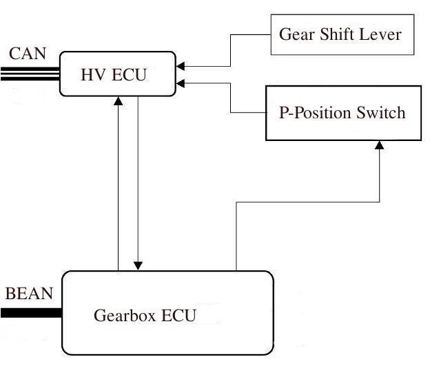
the Electronic Power Steering (EPS) ECU. The same problem occurs with the gear
as can be seen in Figure 5.3. There the gearshift sends its state to the HV ECU,
that sends the state through the CAN bus and directly to the Gearbox ECU, which
controls the gear.
So if this is the case, it seems not possible to control the actuators without a mod-
ification of the CAN bus. There is still a possibility that another ECU has an
influence of the behavior of a state, or is even able to control it. But to find out
which ECU can change the state is not possible without any information from the
producer.
In some cases the sensor and the actuator are linked to different ECUs, which
are connected together over the CAN bus. For example during cruise mode, the
gaspedal sensor is linked to the HV ECU, that computes a torque demand and sends
this through the CAN bus to the engine control unit, which controls the throttle25 5.2. Results of Control Actuators
Figure 5.2: CAN diagram of EPS.
Figure 5.3: CAN diagram of the gearshift.
valve. This is shown in Figure 5.4. It looks like it is possible to control the throttle
valve through the CAN bus, but this works only for the internal combustion engine.
Since it is not possible to control the motor-generators, we have to make sure that
these are disabled. Analog to the gaspedal is the regenerative part of the break
controlled through the CAN bus. This sounds nice, but the problem is, that we
have to be able to generate exactly the necessary CAN message. Even if we could
create and send this message, the real message will still be sended and the ECU of
the actuator receives two different messages.Chapter 5. Results 26 Figure 5.4: CAN diagram of the signal from the gaspedal to the throttle valve.
Chapter 6

Conclusion and Further
Work

There were two main goals for this project, namely to display different states in
GUI and to control some actuators without modifying the CAN bus. We saw that
there are a lot of informations in the CAN messages. The hard part of reading out
desired states was to find out, which byte of which message represents the required
informations. Once we knew that, it was straight forward to transform the bytes
to desired values. If we want to use the states for a feedback control we have the
problem, that the sample frequencies of the states are not constant and can be
low. This is because we loose massages since the transfer rate of the DLC3 port is
limited. If we would add a new ECU as a node to the CAN bus, the limitation of
the transfer rate could be avoided, but this has to be tested.
It was much harder to fulfill the control task. As descriped in Section 5.2 it is
possible to send messages through the CAN bus, but there are some problems to
control existing nodes. One problem is that some actuators are not controlled
through the CAN bus. That means the sensors and the actuators are directly
connected to the corresponding ECU, which controls the state. This is the case for
the steering wheel (see Figure 5.2), and the Gear (see Figure 5.3). A second problem
is that even if an ECU, that controls an actuator, considers CAN messages from
other ECUs and we are able to create and send this messages, the controlling ECU
receives both, the original and the faked message. This is the case for the throttle
valve as you can see Figure 5.4. These problems can only be solved by modifying
the CAN bus or the electric of the Prius. A possible solution could be to change the
signals from the sensors or to the actuators electronicaly without using the CAN bus
or to add electrical switches to neglect the original signals. Another approach is to
reprogram the ECU in such a way that it considers also some new CAN messages
for the output. The drawback is, that it could be dangerous to modify working
ECUs that controls the steering angle or the throttle valve, because if they are not
fully reliable anymore the car could get out of control.
But even with this solutions it is not guaranteed to control every state. A simple
solution is to add ECUs to the CAN bus as new nodes. This ECUs could be able
modifiy sensor signals and/or control actuators. This solution has the advantage
that it is not necessary to reprogram the existing ECUs, so safety is guaranteed by
human intervention.

                                         27
Chapter 6. Conclusion and Further Work 28
Bibliography

 [1] P. Lamon, S. Kolski, R. Siegwart: The SmartTer - a Vehicle for Fully
     Autonomous Navigation and Mapping in Outdoor Environments. Swiss Federal
     Institute of Technology Zurich, Autonomous Systems Lab (ASL).
 [2] A. Vass: My CAN Project.
     http://www.vassfamily.net
 [3] The Team Lux.
     http://www.team-lux.com

 [4] Toyota Motor Corporation (TMC): Worldwide Prius Sales Top 1 Mil-
     lion Mark. Japan, May, 15, 2008.
     http://www.toyota.co.jp/en/news/08/0515.html
 [5] Wikipedia: Hybrid Synergy Drive.
     http://en.wikipedia.org/wiki/Hybrid Synergy Drive
 [6] Toyota Motor Corporation (TMC) Manual, Prius NHW20.
 [7] Wikipedia: Electrical Control Unit.
     http://en.wikipedia.org/wiki/Electronic control unit

 [8] H. Engels: CAN-BUS. In Franzis Verlag GmbH, Second Edition, 2002, Pages
     49-118.
 [9] Wikipedia: Controller Area Network.
     http://en.wikipedia.org/wiki/Controller area network
[10] Toyota Motor Corporation (TMC): Toyota Germany.
     http://www.toyota.de
[11] Prius PHEV TechInfo.
     http://www.eaa−phev.org/wiki/Prius PHEV TechInfo

                                       29
You can also read