ROBOSUB 2021 TECHNICAL DESIGN REPORT - BUMBLEBEE
←
→
Page content transcription
If your browser does not render page correctly, please read the page content below
NATIONAL UNIVERSITY OF SINGAPORE (BUMBLEBEE AUTONOMOUS SYSTEMS)                                                     1

             RoboSub 2021 Technical Design Report
                    National University of Singapore (Bumblebee Autonomous Systems)

 Amadeus Aristo Winarto, Chen Sirui, Chew Zhi En Samuel Joshua, Chin Zheng Hao, Goh Jie Xuan Delvin, Gokul Rajiv,
  Gowthaman Aravindan, Hashir Zahir, Hou Lin Xin, Joshua Nathanael, Justin Foo, Kaitlyn Ng Ke Yi, Kang Qingxuan,
    Lee Chan Wai, Lee Shi-An Matthew, Lim Sheng Wei, Low Zhi Jian, Lum Chang Xin Shawn, Nathania Santoso,
   Ng Cheng Yang Titus, Ng Xinyi, Ng Yong Jie, Ng Zhia Yang, Nguyen Minh Nguyen, Niu Xinyuan, Png Qun Shen,
   Quek Wei, Rani Karthigeyan Rajendrakumar, Seow Alex, Stevanus Williem, Tan Chew Miang Edwin, Teo Ru Min,
                                         Yam Jin Ee Dmitri and Zhu Tianqi

Abstract—For RoboSub 2021, Team Bumblebee’s strategy         A. Development Efforts
involves simultaneously deploying the BBAUV 3.99 and
the BBAUV 4.0 to complete the tasks efficiently, using       During the first half of the year, lab access was
acoustic subsystems for inter-vehicular communication.       limited due to COVID-19 restrictions. As a result,
The mechanical design of the BBAUV 4.0 is optimised          our whole team worked remotely, with the Mechan-
for space and weight, offering vastly superior manoeu-       ical team relying on our accurate CAD models to
vrability while eliminating the weight penalty incurred by
                                                             continue development of our vehicles. We continued
the BBAUV 3.99. Electrical work centred on improving
ease-of-access to components and decoupling individual       to finalise designs and send parts for manufactur-
subsystems, reducing turnaround time when debugging.         ing during the lockdown period, allowing us to
Software development focused on improving the vision         rapidly assemble and test them once the lockdown
pipeline and implementing a behaviour tree-based mission     lifted.
planner to allow for quicker iterations during testing and
an easier understanding of the AUV’s behaviour. The          Even after restrictions were partially lifted, our
team’s limited access to in-water testing was supplemented   physical pool testing opportunities were still
using hydrodynamic simulations to tune the AUV’s control     severely limited. To make full use of our time, we
systems, and custom sensor plugins were developed for our
Gazebo simulator. Testing time was used to qualify our
                                                             split our team into two, deploying both vehicles at
simulation results and improve our models.                   every test. One team focused on testing our new
                                                             algorithms using the robust BBAUV 3.99, while
                                                             the other team focused on finalising development of
           I. C OMPETITION S TRATEGY
                                                             the BBAUV 4.0. To further increase the efficiency
For RoboSub 2021, we plan to deploy both our                 of physical testing, we developed hydrodynamic
BBAUV 3.99 (Fig.1) and BBAUV 4.0 (Fig.2) to                  models of the AUVs, using Computational Fluid
complete all the competition tasks. We noted that            Dynamics (CFD) simulation conducted in Ansys
although we were previously able to achieve good             Fluent. Control law partitioning was used to identify
results with only the BBAUV 3.99, the past 3                 relevant system equations, providing a guideline for
physical RoboSub competitions were won by teams              the tuning of the Proportional–Integral–Derivative
deploying two vehicles. Deploying two vehicles               (PID) controllers, reducing the number of parame-
allows us to significantly reduce our competition            ters required to tune the PID controller from 24 to
run time as they can complete tasks simultaneously,          8.
while also acting as backups in case one vehicle
fails to perform a task. Furthermore, we are also            For our Software team, we expanded our Gazebo
able to optimise each vehicle for a specific set of          simulations to add a variety of task obstacles, al-
tasks, which we will discuss below. Lastly, while            lowing us to test the controls and sensors of the
the new vehicle was still under development, our             AUV without requiring physical pool tests. Fur-
software team was able to use the stable BBAUV               thermore, we were able to tune the parameters of
3.99 platform to deploy and test our software sys-           our simulated vehicle to closely match our real
tems.                                                        vehicle, using data calculated by the aforemen-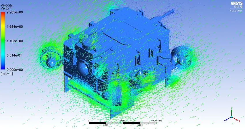
NATIONAL UNIVERSITY OF SINGAPORE (BUMBLEBEE AUTONOMOUS SYSTEMS)                                               2

tioned hydrodynamic models. This allowed us to          such as our new electronically-controlled actuation
accurately simulate the competition tasks and test      system, replacing the heavier and less reliable pneu-
various configurations of our mission planner for       matics used on BBAUV 3.99.
their effectiveness. This way, we were able to use
pool time to rectify errors we couldn’t predict in      C. Course Strategy
the simulation, such as reflections from the water
                                                        Being the faster of the two, we aim to deploy the
surface interfering with our camera.
                                                        BBAUV 4.0 for the With Moxy and Choose Your
                                                        Side tasks first. For the remaining tasks, we plan to
B. Competition Vehicles                                 use the BBAUV 4.0 to complete the pinger tasks
Our first vehicle, the BBAUV 3.99, was entered in       (Survive The Shootout and Cash or Smash), while
RoboSub 2018 and 2019. It was developed as both         assigning the BBAUV 3.99 to the marker following
a competition vehicle as well as a research and         tasks (Make the Grade and Collecting). We expect
development vehicle for commercial applications.        both vehicles to complete their tasks at the same
However, its high weight incurs a large penalty         time (the pinger tasks are more time-consuming,
under the RoboSub scoring system, and its large         but the BBAUV 4.0 is faster). If time permits, the
size prevents it from doing certain tasks effec-        vehicles will swap their assigned tasks and attempt
tively.                                                 to get a better score.
                                                        To facilitate this dual-vehicle strategy, we developed
                                                        an inter-vehicle communication system. In order to
                                                        prevent conflicts, each vehicle publishes the task
                                                        that it is currently attempting; only when both
                                                        vehicles signal completion of all their tasks will they
                                                        swap their assignments. Furthermore, in terms of
                                                        collision avoidance while navigating between tasks,
                                                        each vehicle publishes its current and predicted lo-
           Fig. 1: 3D model of the BBAUV 3.99.          cations; if the predicted locations are within 5m, the
                                                        vehicles will move to different depths to allow them
Our second and newest vehicle, the BBAUV 4.0,           to safely pass each other. Lastly, the inter-vehicle
is designed solely for RoboNation competitions. A       communication system allows both our vehicles to
much smaller and lighter vehicle, it is intended to     share the positions of each task with each other,
resolve the weaknesses inherent in the BBAUV 3.99       allowing for seamless swapping of tasks.
while maintaining similar capabilities.
                                                        In terms of the individual tasks, we make use of
                                                        a sensor fusion approach, together with a tech-
                                                        nique known as structure from motion in our vi-
                                                        sion pipeline. By combining our sonar images with
                                                        object detection using machine-learning methods,
                                                        we are able to accurately localise and identify task
                                                        objects like the buoys in the Make the Grade task.
                                                        For identifying the torpedo cutouts in the Survive
                                                        the Shootout task, we further augment this with
                                                        traditional computer vision techniques for detecting
                                                        the border colour.
           Fig. 2: 3D model of the BBAUV 4.0.
                                                        To complete the Collecting task, we first use the
While developing our new BBAUV 4.0, we reused           bottom-facing camera to follow the orange markers
existing designs and technologies as far as possible,   to the general area of the bins; we then search for
to reduce the cost of developing an additional vehi-    them by moving in a square-shaped spiral path to
cle. However, improvements made to the BBAUV            balance the efficiency of detection and accuracy of
4.0 were also back-ported to the BBAUV 3.99,            motion as recorded by our Doppler Velocity Log
NATIONAL UNIVERSITY OF SINGAPORE (BUMBLEBEE AUTONOMOUS SYSTEMS)                                                   3

(DVL), using our aforementioned vision pipeline for
identifying the bins themselves. To lift the cover, our
plan is to leverage our position-based PID controller
(discussed below) to accurately position the vehicle,
utilising a fixed grabber arm to grab the cover’s
handle.
Bringing together these task-specific strategies is
our mission planner. In previous years, we used a
Finite State Machine (FSM) based mission planner
due to the abundance of existing resources, and their
relative ease of implementation. In our experience                  Fig. 3: Internal layout of the main hull.
however, adding or removing states from an FSM-
based planner is prone to human-error by virtue of
needing to consider the complexities of the transi-       Our vehicle also has a transparent window to ob-
tions and internal states in the state machine. This is   serve internal components and a display screen
only exacerbated under high-stress conditions, such       which highlights the vehicle’s internal pressure,
as within the 15-minute time limit of a run. As such,     battery level and other important indicators.
we moved to a Behaviour Tree (BT) based mission
planner this year, and its benefits will be elaborated
                                                     2) Cooling System
under the Design Creativity section.
                                                     The BBAUV 4.0’s cooling system takes advantage
                                                     of our aluminium hull by using thermal adhesive
             II. D ESIGN C REATIVITY                 tape to dissipate heat from our Single-Board Com-
A. Mechanical Sub-System                             puter (SBC) and Graphics Processing Unit (GPU)
1) Design of Main Hull                               directly onto the hull walls (Fig.4) and, by exten-
                                                     sion, the surrounding water. This simple and passive
In designing the main electronics hull of the
                                                     heat dissipation method obviates the need for addi-
BBAUV 4.0, we looked for ways to reduce wasted
                                                     tional components and complexity for component
space on the vehicle. Noting that most commercially
                                                     cooling.
available boards are rectangular, we decided to make
the hull rectangular to increase its packing effi-
ciency. Compared to the already packed cylindrical
hull of the BBAUV 3.99, the BBAUV 4.0 hull
achieves space savings of 50% while preserving
previous capabilities.
Rectangular hulls are more susceptible to warping
at high pressures, so our hull is made of Computer
Numerical Control machined aluminium instead of
the usual acrylic pieces. Finite Element Analysis
was performed to optimise the shape while ensur-
ing that it could withstand its rated pressure of 3
bars. The hull also contains an internal aluminium              Fig. 4: SBC mounted with thermal adhesive tape.
wall which improves the structural rigidity of the
AUV, while doubling as method of isolating the
electrically noisy components (eg. the Electronic         3) Design of Battery Hull
Speed Controls) from the sensors, like the Inertial       Another creative aspect of our new AUV is the
Measurement Unit (IMU) and acoustic systems.              battery hull, manufactured using novel 3D metal
We also implemented an innovative slot mounting           printing technology. We embedded internal lattices
mechanism, which enables mechanical and electri-          and isogrid patterns for the walls and base of
cal modularity (Fig.3).                                   the battery hull, increasing the rigidity-to-weight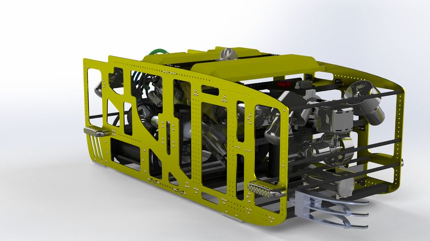
NATIONAL UNIVERSITY OF SINGAPORE (BUMBLEBEE AUTONOMOUS SYSTEMS)                                                   4

ratio. By using 3D-printing, we were also able          The new dropper uses a single servo motor to
to manufacture tight corners, which are difficult       control the position of the blocking arms, while the
to create using traditional methods. This allows        new torpedo launcher uses a compressed spring and
the battery to fit exactly into the hull, once again    latch system that is actuated via a servo motor. The
minimising internal space wastage. Together, these      grabber system utilises the commercial off-the-shelf
factors significantly reduce the vehicle’s weight and   Blue Robotics Newton Gripper, due to its robustness
volume.                                                 and simplicity for tasks that require manipulating
                                                        PVC pipe obstacles.

                                                        5) AUV Indicator Lights
                                                        To provide real-time, at-a-glance feedback of the
                                                        vehicle’s state during autonomous testing and com-
                                                        petition runs, the BBAUV 3.99 uses internal LED
          Fig. 5: Isogrid layer of the battery hulls.
                                                        strips, which are visible through its transparent hull.
                                                        To maintain this functionality with the BBAUV
                                                        4.0’s opaque aluminium hull, we developed an in-
The rectangular design of both the main and battery
                                                        house RGB lighting system that is entirely enclosed
hulls also allows them to be directly connected
                                                        within a Blue Robotics M10 Penetrator, requiring no
by right-angled SubConn Low Profile connectors,
                                                        external cabling. Its low profile design reduces drag,
further cutting weight by reducing the length of
                                                        while still being externally visible.
cabling required.
                                                     We determined that the off-the-shelf Blue Robotics
4) Design of Actuation Systems                       lights were unsuitable since they could only display
                                                     a single colour, making it difficult to differentiate
The BBAUV 3.99 previously used a pneumatic sys- between states, or requiring more than one light to
tem for the ball dropper and torpedo launcher. How- do so.
ever, this system requires a buffer to re-pressurise
the tank between actuations, and also necessitates
                                                     B. Electrical Sub-System
a separate hull to contain the pneumatic valves,
occupying both weight and space.                     1) Design of Electrical Architecture
                                                     There are two main communication channels used
Our vision to reduce the weight, footprint and
                                                     in our electrical architecture: Controller Area Net-
maintenance time of the new BBAUV 4.0 led us
                                                     work (CAN) and Ethernet. Ethernet is used for
to develop an electronically controlled actuation
                                                     systems requiring high bandwidth, while CAN is
system (Fig.6), removing the need for air canisters
                                                     used for communication between the embedded
and an additional hull.
                                                     systems.

                                                              Fig. 7: Communication architecture block diagram.

                                                        Our custom-designed Power Monitoring Board
                                                        reads the battery charge through a fuel gauge IC,
           Fig. 6: BBAUV 4.0 Torpedo Launcher.          allowing us to display an estimate of the remaining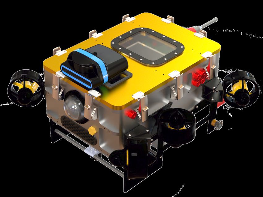
NATIONAL UNIVERSITY OF SINGAPORE (BUMBLEBEE AUTONOMOUS SYSTEMS)                                             5

                                                       directly connect to systems over the CAN. Addition-
                                                       ally, an Ethernet controller is also used to provide
                                                       direct access to the systems on the CAN without
                                                       going through the SBC. This redundant connection
                                                       allows us to access both the CAN and the Ethernet
                                                       networks even during SBC failure, which lets us
                                                       retain control over the AUV in such an event. On top
                                                       of that, we are able to perform remote hard-resets
          Fig. 8: Power architecture block diagram.
                                                       on our electronics by toggling solid state switches,
                                                       without the need to open the hull.

operational run-time of the vehicle. Additionally,     4) Acoustic signal processing
this monitoring system allows our control board        In the BBAUV 4.0, the acoustic subsystem uses an
to prioritise power to systems and selectively dis-    automated programmable gain amplifier that allows
able them in low-power scenarios. Finally, we also     us to obtain a uniform amplitude of the incoming
integrated an under-voltage protection system that     ping, enabling more reliable measurements. This
shuts the electronics down to prevent damaging the     results in both a reduction in signal clipping, and
batteries if their voltage drops too low.              consistent outputs regardless of distance from the
By incorporating a load-balancer between the 2 bat-    pinger. Scaling of the amplifier’s gain factor is done
teries, we were able to make them hot-swappable, so    by comparing the ratio between the optimal and
that the vehicle can remain running during battery     the current amplitude of the ping, which is done
changes — minimising operational downtime. Fur-        on the Data Acquisition (DAQ) board. To increase
thermore, sensitive components are protected from      reliability and reduce false positives, we check the
any electrical noise with galvanic isolation between   signal-to-noise ratio on the extracted ping, weighted
internal electronics and inductive loads.              towards known sources of noise. Furthermore, ping
                                                       extraction is performed using short-time Fourier
2) Backplane System                                    transformation with a dynamic thresholding method,
The backplane design adopted ensures that the elec-    allowing the ping to be accurately extracted with
tronics are no longer mounted on the end cap, but      little latency even in noisy environments.
sit in the hull instead. This allows the electrical
system to employ multiple backplanes, segregating
the low and high level circuitry into sections. These
backplanes can be easily accessed by opening the
top lid in a plug-and-play fashion, allowing us to                  Fig. 9: Acoustics flow diagram.
easily remove and replace boards for maintenance
without being obstructed by other internal compo- The TC4013 hydrophones used for localisation can
nents.                                                double as transmitters and receivers for acoustic
                                                      communications. Hence, to integrate communica-
Another benefit of decoupling the backplanes is to
                                                      tion functionalities into the existing acoustic local-
allow each system to function independently. This
                                                      isation hardware, additional transmit and receive
allows failures in the system to be unambiguously
                                                      channels were integrated into the signal condi-
traced, making debugging easier. It also isolates
                                                      tioning and DAQ board, while firmware was also
electrically sensitive equipment, such as our IMU
                                                      developed for the DAQ to provide signal encoding
and acoustics boards, from the electrical noise gen-
                                                      and decoding capabilities.
erated by the other electronics, thus increasing the
accuracy of sensor measurements.                      The integration of acoustic inter-vehicular com-
                                                      munications into the existing acoustic localisation
3) Communication network                              hardware helps in minimising any cross-interference
To improve inter-system communication, we im- through precise timing of the communication sig-
plemented a CAN link, which enables the SBC to nals. As a Field-Programmable Gate Array (FPGA)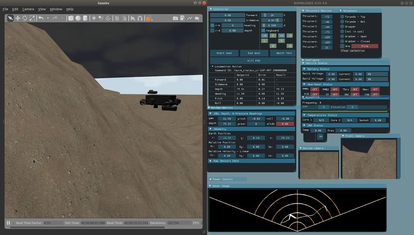
NATIONAL UNIVERSITY OF SINGAPORE (BUMBLEBEE AUTONOMOUS SYSTEMS)                                               6

is utilised for processing, communication and data       Not only can nodes be extensively re-used, trees can
acquisition can be performed in parallel, and the        also be re-used as parts of other larger trees; this
addition of communication functionality does not         high level of composability and abstraction allows
affect localisation.                                     us to define increasingly complex robot behaviours
                                                         with ease. Furthermore, our BT mission planner
We use Quadrature Phase Shift Keying (QPSK) as           allows for tree structures and parameters, which are
our modulation technique, as the low transmission        encoded in XML files, to be changed at runtime
sensitivity of the TC4013 results in a low signal-to-    without requiring code recompilation, saving pre-
noise ratio not suitable for amplitude shift-keying      cious time in competition settings.
(ASK), and the low bandwidth of frequency shift-
keying (FSK) make it undesirable. Error detection
is done via an 8-bit Cyclic Redundancy Check
(CRC8), and the stop-and-wait automatic repeat-
request (ARQ) is utilised to ensure reliable data
transfer.

5) WiFi Integration
To increase our testing efficiency, we connected a
WiFi dongle to the AUV’s SBC via USB. This
allows us to remote into the vehicle simply by                      Fig. 10: Sample BT-based mission plan.
surfacing the vehicle, without having to roll out a
tether from our Operator Control System, saving a        We use a graphical BT tool, Groot (Fig.10), to easily
great deal of time. This allows us to quickly con-       modify the existing BT using a visual editor. This
nect to the vehicle to send commands, reconfigure        tool also allows us to observe the BT in real-time as
our mission planner and other parameters, or send        it executes, which is invaluable in saving time and
shutdown/restart commands. As an added benefit,          energy when trying to debug the program flow of
the wireless connection acts as an additional fail-      the mission planner.
safe connection to the AUV.
                                                         2) Vision Pipeline
                                                         Our system adopts a multi-sensory approach for
C. Software Sub-System                                   tracking and localising objects of interest, by fusing
1) Mission Planner                                       the data obtained from the camera and sonar with
                                                         the AUV’s odometry. Various filters and threshold-
As previously mentioned, we transitioned to a BT-
                                                         ing techniques are used on the sonar image to extract
based mission planner this year due to its flexibility
                                                         objects of interest. The sonar is used to determine
and ease of maintenance. Based on the Behav-
                                                         the range R and azimuth θ to the identified objects,
iorTree.CPP package, the BT-based mission planner
                                                         while the elevation φ is determined by projecting
offers many advantages over the traditional FSM
                                                         the φ search space and matching detections from
planner. Unlike the layout of an FSM, the BT’s tree
                                                         the sonar to that of the camera.
structure makes it easy to immediately interpret at
a glance the robot’s behaviour in various situations.    A particle filter is then initialised to track the 3D
This linear structure and the well-defined transitions   position and velocity of identified objects. The par-
between node states in a BT also make it easier          ticle model is updated based on vehicular dynamics,
to configure robot behaviours simply by dragging         obtained from the DVL and IMU. The robustness
nodes around, without having to worry about tran-        of our algorithm is improved by weighting each
sitions between a large number of states. This allows    particle based on several heuristics, such as optical
BT mission planners to react to more situations,         velocity of the sonar pixel and the object dimen-
while it would take exponentially more states and        sions. The particles are then resampled, with those
transitions with an FSM mission planner to achieve       having a higher weight being more likely to be
similar behaviours.                                      selected.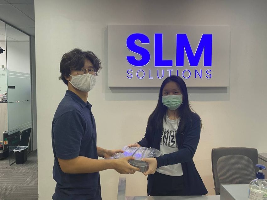
NATIONAL UNIVERSITY OF SINGAPORE (BUMBLEBEE AUTONOMOUS SYSTEMS)                                               7

3) Control System                                        5) Non-linear PID
                                                         To improve the existing position-based follower, we
                                                         implemented a non-linear PID controller, which in-
                                                         creases the vehicle’s responsiveness and minimises
                                                         the wind-up of the integral term. Using additional
            Fig. 11: Unified control architecture.       feedback from the AUV’s current state, we de-
                                                         couple the compensation for higher-order vehicle
A unified control architecture was developed to          dynamics, which cannot be easily done using simple
increase the modularity of the existing navigation       linear control schemes. To calculate the optimal
stack. Its modular design allows us to share the         gain values for the PID controller, we ran CFD
control system for both the BBAUV 3.99 and               simulations to obtain the vehicle’s hydrodynamic
BBAUV 4.0, mitigating the drawbacks of a dual-           properties, which are discussed below.
vehicle deployment. To accommodate the different
thruster layouts on each vehicle, instead of sending            III. E XPERIMENTAL R ESULTS
thrust commands directly, the control system uses
thrust matrices that describe the mapping from each A. Pressure Rating
axis of movement to thruster commands, unique for To ensure reliability of the AUV’s hulls, the
each vehicle.                                         BBAUV 4.0 was pressure tested at 3 bars of pressure
                                                      in a pressure testing tank. This confirmed that the
This modular architecture provides greater code vehicle meets its original design specifications, and
separation between the high- and low-level control verifies the reliability of its waterproofing.
of the AUVs, supporting rapid testing and imple-
mentation of different low-level control strategies
and thruster configurations for each vehicle. It also B. Hydrodynamic Model
allows higher-level control strategies, such as the A hydrodynamic model of the BBAUV 4.0 was
one described below, to be easily reused across our generated (Fig.12) and CFD simulations were con-
vehicles.                                             ducted to reduce the number of parameters needed
                                                      to tune the PID controller.
4) Velocity-based Path Follower                          We used control law partitioning to identify relevant
We developed a path following algorithm based on         system equations, providing a guideline for tuning
velocity setpoints, instead of a traditional position-   the controllers. This approach greatly improved the
based algorithm. This new algorithm estimates the        efficiency of PID tuning: we were able to cut down
Menger curvature of the forward path of the vehicle,     the number of parameters to 1 value per rotational
with a certain look-ahead distance. Based on the         axis, and the time taken to only an hour.
curvature of the path and its cross-track error with
the vehicle’s current position, we calculate velocity
setpoints which are sent to the PID control loop,
which will calculate the correct thruster outputs to
achieve the desired velocity.
In RoboSub 2019, we deployed a purely position-
based following algorithm, due to its fine control
ability, crucial for the various manipulation tasks.                Fig. 12: Flow analysis in Ansys Fluent.
However, that algorithm performed poorly when
required to traverse around obstacles, for example       Unfortunately, the hydrodynamic model we devel-
during the narrow gate challenge. In situations such     oped exhibited discrepancies from the AUV’s real
as these, we can use the new velocity-based path         world performance during open loop testing, while
follower, while retaining the existing position-based    limited physical testing prevented further tuning of
follower for tasks requiring precise positioning of      the model. We aim to further develop and refine the
the vehicle.                                             model once physical restrictions relax.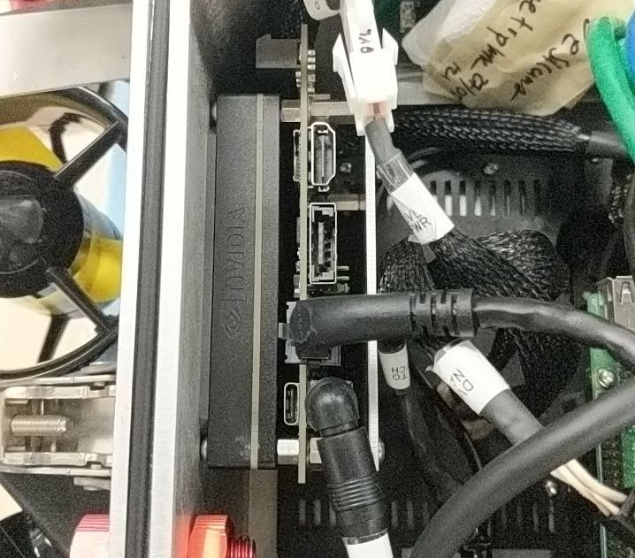
NATIONAL UNIVERSITY OF SINGAPORE (BUMBLEBEE AUTONOMOUS SYSTEMS)                                         8

C. Cooling system
During bench testing for the operations of the
BBAUV 4.0, the IMU magnetometer readings were
inaccurate, and we traced the source of the problem
to the magnetic field generated by the DC motor in
our water cooling pump (Fig.13).

                                                                  Fig. 14: Gazebo-ROS AUV simulation.

                                                      Fossen model for nonlinear modelling of underwater
                                                      vehicles [1].
                                                    A custom sonar plugin was also developed for
                                                    the simulator to simulate the Oculus sonar on the
             Fig. 13: Magnetic noise generated.     BBAUV 4.0. The sonar image is generated from the
                                                    aerial perspective of a point cloud obtained from a
After many attempts to resolve the problem, includ- depth camera plugin offered by Gazebo.
ing encasing the motor in a steel box (while it did
                                                    This end-to-end simulator allows new features to be
reduce the magnetic noise, it was not sufficient),
                                                    quickly tested in a virtual environment for logic and
we decided to abandon the liquid cooling system
                                                    architecture issues, helping to speed up processes
entirely; due to the compact nature of our hull,
                                                    by tightening the feedback loop between writing
it was deemed unlikely that we could achieve an
                                                    and testing code, decreasing turnover times for more
acceptable level of isolation between the IMU and
                                                    agile software development.
the motor that would not affect the magnetometer’s
accuracy.                                           As mentioned above in the competition strategy, we
                                                    have also added task obstacles to the simulator this
As a replacement, we developed a new design for
                                                    year, which allows us to quickly and effectively
the cooling system as previously mentioned. To
                                                    prototype our task-specific logic for our mission
evaluate the new cooling solution for the AUV, a 1-
                                                    planner.
hour stress test was conducted on our Jetson Xavier
and SBC, and maximum temperature data was col-
lected. We found that the temperatures of our SBC E. MATLAB Simulator
and GPU hit a maximum of 68°C, which is well
                                                    A simplified simulator was designed in MATLAB
below the maximum recommended temperature of
                                                    Simulink using the multibody add-in (Fig.15); it is
80°C.
                                                    designed with the sole purpose of simulating the
                                                    vehicle model and control systems of our AUV with
D. Gazebo-ROS Simulator                             high fidelity.
In view of the COVID-19 pandemic, physical
testing of the AUV system was suspended; to
support continuous development of our software
stack, we developed a simulator for the new AUV
(Fig.14).
The AUV simulator was developed on top of the
UUV Simulator, a package that contains Gazebo                    Fig. 15: MATLAB simulation.
plugins and ROS nodes for simulating physics and
sensors of AUVs. Through both hydrodynamic sim- The use of blocks in Simulink (Fig.16) facilitates
ulations and real world testing, we were able to rapid experimentation and tuning of different con-
finely tune our vehicle’s parameters, based on the trol schemes.
NATIONAL UNIVERSITY OF SINGAPORE (BUMBLEBEE AUTONOMOUS SYSTEMS)   9

           Fig. 16: Simulink blocks for the simulator.

This also allows members from the Mechanical sub-
team, who are not as well-versed with the software
architecture, to work on developing and tuning con-
trol systems directly. This simulation stack allows
us to iterate more quickly when tuning the control
system, and in conjunction with the hydrodynamic
simulation discussed above, lets us quickly and
effectively tune our controls system.

              ACKNOWLEDGEMENTS
Team Bumblebee’s development and achievements
would not be possible without the help from various
organisations and people. The team would like to
express their deepest gratitude to the sponsors (Re-
fer to Appendix C), including the Title Sponsors
— National University of Singapore (NUS), and
Platinum Sponsors — DSO National Laboratories,
and Future Systems and Technology Directorate
(FSTD). In addition, the team would also like to
thank Sport Singapore and the Republic of Singa-
pore Yacht Club for their continuous support.

                       R EFERENCES
[1] T. I. Fossen, Handbook of marine craft hydrodynamics and
   motion control. Hoboken N.J.: Wiley, 2021.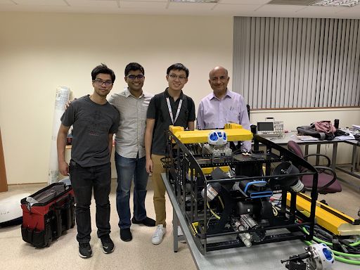
NATIONAL UNIVERSITY OF SINGAPORE (BUMBLEBEE AUTONOMOUS SYSTEMS)                                                       10

                                               A PPENDIX A
                                        C OMPONENT S PECIFICATIONS

 Component      Vendor                Model/Type                   Specifications                           Cost

 Main Hull      Samco Enterprise,     Custom Aluminium             Custom                                   $2,700
                Feimus Engineering    Milling
 Frame          Cititech Industrial   Custom Aluminium Laser-      Custom                                   Sponsored
                                      cut
 Battery Hull   SLM Solutions         Custom Aluminium             Custom                                   Sponsored
                                      Selective Laser Melting
 Waterproof     SubConn Inc.,         Assorted Micro and Low-      Peak Depth: 300 bar                      Sponsored
 Connectors     MacArtney             profile Series
 Thrusters      Blue Robotics         T200                         —                                        $176 ea
 Motor          Blue Robotics         Basic ESC                    —                                        $27 ea
 Control
 High-level     Raspberry Pi          RPi 3 Model B+               1.4GHz 64-bit quad-core processor        $39
 Control
 Actuators/     In-house              Custom design                ABS                                      Sponsored
 Manipulators
 Battery        Tattu                 Custom-made 4-cell battery   16000 mAh                                $120 ea
 Battery        In-house              Custom-made circuit board    Custom                                   Sponsored
 Monitoring
 System
 Power          Murata                UWQ-12/17-Q48PB-C            204W Isolated 24V-12V                    $52
 Isolator                             UVQ-24/4.5-D24P-C            108W Isolated 24V-12V                    $67
 Single Board   AAEON                 GENE-KBU6                    Intel Core i7-7600U                      Sponsored
 Computer                             BIO-ST03-P2U1                Intel i210
 GPU            Nvidia                Jetson Xavier                AGX Module                               $999
 Internal       In-house              CAN/Ethernet                 1000kbps/1000Mbps                        Sponsored
 Comm
 Network
 External       In-house              Ethernet                     1000Mbps                                 Sponsored
 Comm
 Interface
 IMU            Sparton               AHRS-8P                      ±1.2 Gauss                               Sponsored
 Doppler        Teledyne Marine       Pathfinder DVL               600kHz Phased Array                      $16,000
 Velocity Log
 Camera(s)      BlackFly S PoE        BFS-PGE-31S4C-C              2448 × 2048 at 22 FPS                    $594
                Gigabit Camera
 Hydrophones    Teledyne Reson        TC4013                       Acoustic transducers                     Legacy
 Sonar          Oculus                M750d                        Dual-Frequency Multibeam Sonar           $21,300
                                                                   (750KHz/1.2MHz)
 Algorithm:     —                     —                            Thresholding, Particle filter, Machine   —
 vision                                                            learning
NATIONAL UNIVERSITY OF SINGAPORE (BUMBLEBEE AUTONOMOUS SYSTEMS) 11
Algorithm: — — Multiple Signal Classification —
acoustics (MUSIC), Short-Time Fourier
localisation Transform (STFT) based Ping
Extraction
Algorithm: — — Short-Time Fourier Transform —
acoustics (STFT), Quadrature Phase Shift
communica- Keying (QPSK)
tion
Algorithm: — — Error State Kalman Filter —
localisation
& mapping
Algorithm: — — BehaviorTree.CPP —
autonomy
Open source — — OpenCV, ROS, PyTorch —
software
Team size — — 35 —
Hardware/ — — 3:1 —
Software
expertise
ratio
Testing time: — — 200 hours —
simulation
Testing time: — — 40 hours —
in-waterNATIONAL UNIVERSITY OF SINGAPORE (BUMBLEBEE AUTONOMOUS SYSTEMS) 12
A PPENDIX B
O UTREACH ACTIVITIES
Ever since our humble beginnings in 2012, Team
Bumblebee has continued to grow, and we have be-
come one of the most accomplished student teams in
the maritime robotics scene. Despite this, we remain
grateful to the community and our sponsors, who
have supported us throughout the years. In order to
bolster our relationship with the community, Team
Bumblebee strongly believes in sharing our knowl- Fig. 18: Industrial visit to SLM Solutions.
edge and experiences with the community.
A. Lab Tour and Sharing Sessions
As part of Team Bumblebee’s public relations cam-
paign, the team extended invitations to various inter-
national teams for visits to our lab, so as to exchange
knowledge and build lasting friendships.
Fig. 19: Collaboration with a local secondary school.
C. Collaboration with Local Schools
Team Bumblebee is collaborating with a local sec-
ondary school to conduct robotics lessons to inspire
the students of age 13–16. The program aims to
teach the students the basics of AUVs, and provide
Fig. 17: Lab visit by a professor from Florida. guidance for them to design and build their very
own AUV.
Despite the COVID-19 pandemic, we have received
multiple emails from teams interested in starting
D. Recruitment of New Members
their own robotics team. We have engaged them
enthusiastically, and hope to meet them in the future
at competitions.
B. Industrial Partnership and Appreciation
Industrial partners are essential for the sustainability
of Team Bumblebee. Without their support, our
team would not have been able to achieve or sustain Fig. 20: Online recruitment session.
excellence. Therefore, industrial visits are organised
with industrial partners to gain experience and first- In order to engage new students starting their uni-
hand exposure to real-world challenges. versity journey, an online recruitment drive was
held as part of the NUS’s Engineering Life fair, E-
SLM Solutions is one of our latest sponsors, who genium. This has provided Team Bumblebee with
have assisted us in manufacturing the battery hulls the opportunity to reach out to a wide audience of
for our new BBAUV 4.0 using metal 3D-printing as freshmen who might be interested in the program,
discussed above. and entice them to join the team.NATIONAL UNIVERSITY OF SINGAPORE (BUMBLEBEE AUTONOMOUS SYSTEMS) 13
E. Hornet Training Program A PPENDIX C
S PONSORS
A. Title Sponsors
NUS (Faculty of Engineering, Innovation & Design
Programme and School of Computing) — For their
cash support, equipment procurement, and academic
support in our project.
B. Platinum Sponsors
Future Systems Technology Directorate (FSTD) —
Fig. 21: Team Hornet working on their Hornet 6.0 vehicle. For cash support.
DSO National Laboratories — For cash support and
Since its inception 6 years ago, the Hornet Train-
technical guidance.
ing Program has evolved into a staple element of
training for the freshmen in our team. Through this
program, we provide new members a platform to C. Gold Sponsors
build an AUV to compete in the Singapore AUV Festo, Cititech Industrial Engineering, Kentronics
Challenge. Our main objective is to challenge the Engineering, MacArtney Underwater Technology,
freshmen to explore and implement bold designs Würth Electronik, AAEON Technology, SLM So-
instead of replicating what others and their prede- lutions and Fugro.
cessors have done.
D. Silver Sponsors
Bossard, SolidWorks, MathWorks, Southco, Samtec
and Sparton.
E. Bronze Sponsors
Edmund Optics and Richport Technology.
F. Supporting Organisations
Republic of Singapore Yacht Club and Sports Sin-
gapore.You can also read