ROOFER'S GUIDE BITUMIN0US MEMBRANES - 2021 EDITION - Soprema
←
→
Page content transcription
If your browser does not render page correctly, please read the page content below
ROOFER’S
GUIDE
BITUMIN0US
MEMBRANES
2021 EDITION
INTRODUCTION
2021 ROOFER’S GUIDE BITUMINOUS MEMBRANES

INTRODUCTION
The quality of a roof construction depends on several factors that
must function together towards a common objective: ensuring
the long-term performance of the waterproofing system.

The main role of a roof is to keep the building dry and protect
it from the weather. In addition, the roof assembly must be
designed to ensure continuous waterproofing through all
elements of the building envelope. The vertical roof elements,
as well as the waterproofing of the various roof details and
penetrations, must therefore be addressed with the same care
as the sealing of the roof field surface. Next to rain, the roof must
also withstand internal condensation and water vapor migration
to prevent the roof components from deteriorating over time.

In addition to protecting against the weather, the roof
components must be stable and properly fixed to the structure.
The fastening and adhesion methods must allow the roof
assembly to withstand thermal cycles and live loads in order
to limit the material deformation that could compromise the
waterproofing. Beyond stability of the materials, the roof system
must also bear the normal negative pressures exerted by the
wind.

Several factors shall be considered so a roof meets its long-term
performance objectives while working as expected:

   The selection of appropriate materials
   The correct design of the roof assembly
   The proper installation of roof system components
   The regular maintenance of the roof

The main purpose of this Roofers Guide is to present the best
practices regarding the installation of modified bituminous
waterproofing membrane systems as recommended by
SOPREMA.

As a preamble to the installation methods, the General
Information section summarizes SOPREMA’s requirements
regarding surface preparation, membrane layout, slope and other
elements to be considered when designing or building a roof.
These requirements, unlike product installation methods, must
be followed to meet the requirements of SOPREMA warranties.
For more information on this subject, please read the “General
Conditions for Roofing Warranties” and the Warranty section of
the SOPREMA website.

In this version of the guide, emphasis has been put on the
installation steps for the different types of SOPREMA modified
bitumen membranes. Descriptions are no longer organized by
product brands but by adhesion methods:

   Torch welded
   Self-adhered
   Mechanically fastened
   Bonded with col adhesive
The Roofers Guide also introduces methods for installing
components other than membrane, namely insulation panels,
support panels, and other main accessories, such as pitch
pockets and liquid membranes.

In conclusion, this Roofers Guide contains information that is
relevant to all installers, professionals in charge of assembly
design, site inspectors, project managers, estimators and any
other person involved in roof construction and looking for answers
regarding the installation of SOPREMA’s main roofing products.

2021 ROOFER’S GUIDE BITUMINOUS MEMBRANES

TABLE OF CONTENTS
1.0. GENERAL INFORMATION                              9

 1.1. Surface Preparation                             9
  1.1.1. Primer Application                            9
  1.1.2. Tools Required                               10
  1.1.3. Drying Time and Coverage Rate                10
 1.2. Properties of the Different Substrates          11
    1.2.1. Concrete Surfaces                          12
    1.2.2. Wood deck                                  12
             1.2.2.1. Planks                          12
             1.2.2.2. Plywood Boards                  12
             1.2.2.3. Oriented Strand Boards (OSB)    13
             1.2.2.4. Treated Wood                    13
             1.2.2.5. Cross-Laminated Timber (CLT)    13
      1.2.3.Steel deck                                13
1.3. Compliance with Standards of Different
      Fastening Methods for Roof System
      Components                                      14

 1.4. Layout of Membranes                             15
      1.4.1. Layout of the Base Sheet Membranes on
             the Horizontal Roof Surface              17
      1.4.2. Temporary Waterproofing                  19
      1.4.3. Layout of the Cap Sheet Membranes on
             the Horizontal Roof Surface              20
      1.4.4. Layout of Flashing Membranes             21
      1.4.5. Use of Cant Strips                       22
      1.4.6. Use of Fastening Bars at the Perimeter   23
 1.5. Slope                                           23

 1.6. STORAGE AND HANDLING                            23

2.0. MEMBRANE INSTALLATION METHODS                    25

 2.1. Heat-Welded Membranes                           25
      2.1.1. Limitations                              26
      2.1.2. Conditioning of Membranes                26
      2.1.3. Installation Methods                     27
              2.1.3.1. Horizontal Roof Surface        27
              2.1.3.2. Flashings                      29
 2.2. Self-Adhesive Membranes                         30
      2.2.1. Limitations                              31
      2.2.2. Conditioning of Membranes                31
      2.2.3. Installation Methods                     32
              2.2.3.1. Horizontal Roof Surface        32
              2.2.3.2. Flashings                      32
 2.3. Mechanically Fastened Membranes                 33
      2.3.1. Limitations                              33
      2.3.2. Conditioning of Membranes                33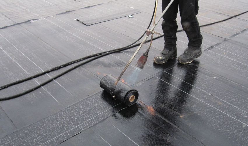
2.3.3. Installation Methods               33
             2.3.3.1. Horizontal Roof Surface   33
             2.3.3.2. Flashings                 34
 2.4. Membranes Bonded with Cold Adhesive       34
      2.4.1. Limitations                        34
      2.4.2. Conditioning of Membranes          34
      2.4.3. Installation Methods               43
            2.4.3.1. Horizontal Roof Surface    35
            2.4.3.2. Flashings                  35
                2.4.3.2.1. Method No. 1         35
                2.4.3.2.2. Method No. 2         36
                2.4.3.2.3. Method No. 3         36
 2.5. Factory-Laminated Base Sheet Boards       37
      2.5.1. Limitations                        37
      2.5.2. Conditioning of the Panels         37
      2.5.3. Installation Methods               37
             2.5.3.1. Field Surface             37
             2.5.3.2. Flashings                 38
3.0. INSULATION INSTALLATION METHODS            49

 3.1. General Information                       40

 3.2. Storage                                   40

 3.3. Polyisocyanurate Boards                   41
      3.3.1 Limitations                         41
      3.3.2. Installation Methods               41
 3.4. Rockwool Boards                           41
      3.4.1 Limitations                         41
      3.4.2. Installation Methods               41
 3.5. Extruded Polystyrene Boards               42
      3.5.1 Limitations                         42
      3.5.2. Installation Methods               42

4.0. SUPPORT PANEL INSTALLATION METHODS 44

 4.1. Limitations                               44

 4.2. Storage                                   44

 4.3. Asphaltic Panels                          44
      4.3.1. Installation Methods               44
 4.4. High-Density Polyisocyanurate Boards      45
      4.4.1. Installation Methods               45
 4.5. Wood Fibre                                45
      4.5.1. Installation Methods               45
 4.6. Perlite                                   45
      4.6.1. Installation Methods               45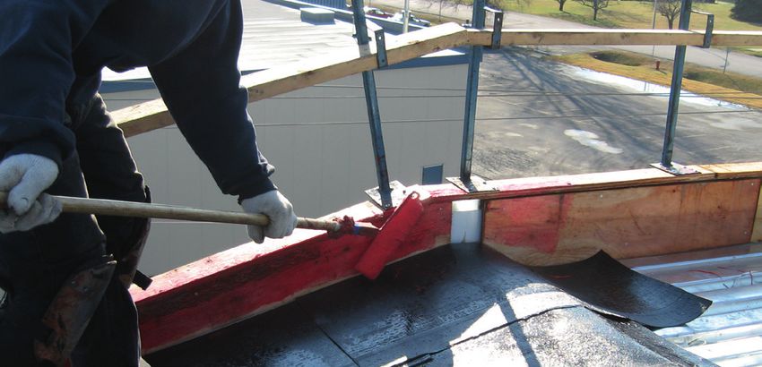
2021 ROOFER’S GUIDE BITUMINOUS MEMBRANES

ACCESSORY INSTALLATION METHODS            47

 5.1. Pitch Pockets (SOPRAMASTIC BLOCK)   47
      5.1.1. Limitations                  47
      5.1.2. Installation Methods         47
 5.2. Liquid Membranes (ALSAN FLASHING)   48
      5.2.1. Limitations                  48
      5.2.2. Application Methods          48
6.0. DETAILS                              50

 6.1. Legend                              51

 6.2. Appendix - list of details          51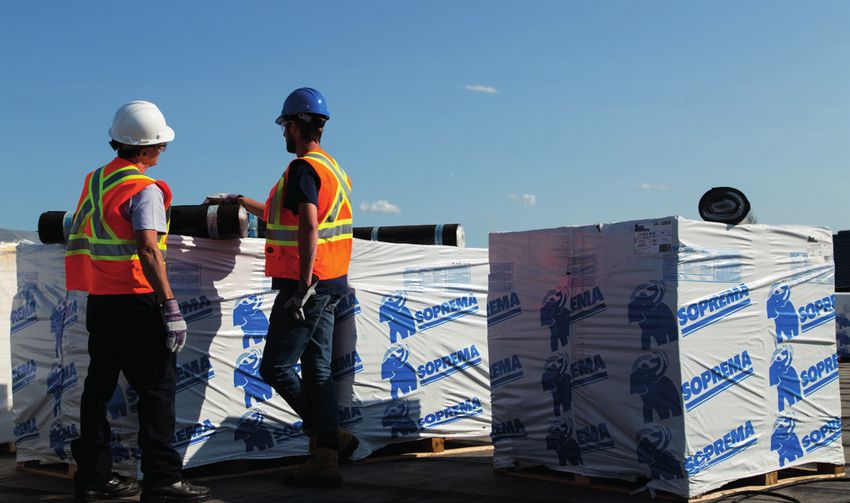
2020 ROOFER’S GUIDE

         1.0.
    GENERAL
INFORMATION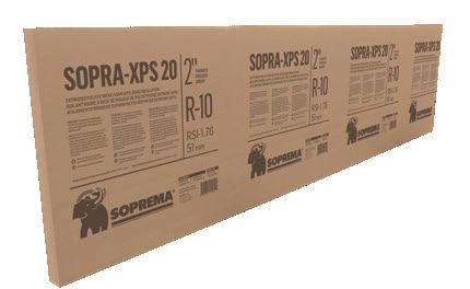
2021 ROOFER’S GUIDE BITUMINOUS MEMBRANES

1.0. GENERAL INFORMATION
 1.1. SURFACE PREPARATION
One of the important steps to ensure the quality installation of
each product of a roof assembly is the preparation of the surface
on which the products will be installed.

To do this, using a primer before the installation of most
membranes is necessary. However, exceptions will be discussed
below, as well as other relevant information about primer
application.

    1.1.1. Primer Application
A primer must be applied before a self-adhesive or heat-
welded membrane is installed. For self-adhesive membranes,
ELASTOCOL STICK primer must be used. For heat-welded
membranes, ELASTOCOL 500 or ANTIROCK primer is used.

Only the following situations don’t require the use of
a primer.
   SOPRAVAP’R on a galvanized steel deck.
   Heat-welded membranes on SOPRABOARD.
   Membranes bonded with cold adhesives.

There may be exceptions. Consult SOPREMA technical bulletins
or documents from the various roof support panel manufacturers
on this topic.

                                                                    9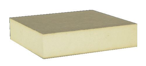
1.1.2. Tools Required
    Primer can be applied using the following tools:
        brushes;
        rollers;
        paint brushes (for small surfaces);
        sprayers (for large surfaces).

                                                                             Never
                                                                             dilute
                                                                             primer.

        1.1.3. Drying Time and Coverage Rate
    Self-adhesive membranes must be installed as soon as possible
    once the primer has dried, or within 2 to 3 hours after application
    of the primer. Waiting too long before their installation could
    contaminate the primed surface and reduce the adhesion
    performance between the self-adhesive membrane and the
    primer. When in doubt, always add a coat of primer.
    Primers used for heat-welded membranes can be applied a few
    days in advance without causing adhesion problems.

                Never use a torch to check if a primer is dry. Use
                your bare hands, making sure primer is dry to touch
                and that the film doesn’t stick to your skin.

                                                                                  APPLICATION
      PRODUCTS               DRYINGTIME1           COVERAGE RATE2
                                                                                  TEMPERATURE

                                  1 to
ELASTOCOL 500                                         0.15 to 0.25 L/m²             No limitation
                                12 hours

ANTIROCK PRIMER             Minimum 1hour             0.15 to 0.25 l/m2                  0 °C

                                                       Porous substrate:
                                                       0.3 to 0.5 L/m²
                                15 min
ELASTOCOL STICK                   to                  Smooth substrate:                 -10 °C
                                1 hour                0.1 to 0.25 L/m²

     1.The drying time of primers may vary depending on temperature and relative humidity.
     Drying times in the table above are indicative only.
     2.Coverage rate is approximate and may vary depending on the porosity and condition of the
     substrate as well as the application technique.
2021 ROOFER’S GUIDE BITUMINOUS MEMBRANES
1.2. PROPERTIES OF THE DIFFERENT SUBSTRATES
Surface preparation depends not only on the type of membrane
installed, but also on the type of substrate. Special care must
be taken according to the substrate type: concrete, wood or
metal. The following section presents the particularities of
several materials not manufactured by SOPREMA that are
commonly found in construction projects. In such cases, these are
recommendations only and approval may be required from the
substrate manufacturers.
The table below shows which type of primer can be used on
different substrates.
TYPE OF PRIMER
ELASTOCOL ELASTOCOL ANTIROCK Noprimer
SUBSTRATE TYPE STICK 500 PRIMER
COMMENTS
required
CONCRETE
Structural concrete √ √ √
Cellular concrete √ √ √
Soundproofing √ √ √
concrete
WOOD
A non-bituminous cover
panel is recommended
Plank √ N/A N/A prior to membrane
installation.
*For membranes bonded
Plywood √ √* N/A with adhesive only
OSB √ N/A N/A
Pressure-treated wood √ N/A N/A
The installation of
membranes on this
Surface-treated wood N/A N/A N/A type of substrate is not
recommended.
Cross-laminatedtimber(CLT) √ N/A N/A
METALS
Steel deck √ √* Optional according to the
condition of the substrate.
*SOPRAVAP’R
Prepaintedsteel(flashing) √ Not required for
heat-welded membranes
Galvanized steel √ √ √
Stainless steel √ √ √
Aluminum √ √ √
Copper √ √ √
111.2.1. Concrete Surfaces
Concrete must be fully cured before application of the
membranes.
A minimum curing time of 14 days is
generally required in the summer. A
longer period may be required in other
Consult the seasons. Curing time also depends on the
contractor who thickness and density of the concrete.
poured the
concrete for more Surfaces must be dry, clean, and free
details about of loose particles, formwork and curing
concrete curing products, irregularities, slurry, laitance
on a specific etc.
project. Concrete slabs must always be primed
according to type of membrane installed.
Surfaces must have a concrete surface profile (CSP as per the
International Concrete Repair Institute) of 3 to 5 for all types of
modified bitumen membranes.
Protrusions along concrete formwork and construction joints
must not exceed 5 mm.
All holes over 5 mm must be filled with bitumen or fast-setting
concrete, depending on the surface condition.
1.2.2. Wood Deck
1.2.2.1. Planks
Wood decks are usually made of softwood, with sap that
dissolves bitumen. This could cause significant deterioration of
the membrane and creates streaks of bitumen under the plank
deck.
There could be severe consequences to installing membranes
over softwood planks. The membranes and the deck itself may
even have to be completely replaced.
If there is a risk that the membranes will be affected by sap,
SOPREMA recommends not installing a bituminous membrane
directly on the plank deck, whatever its function (vapour barrier or
waterproofing membrane).
If this type of deck is made of old planks, the surfaces may be
irregular, and the presence of used nails and screws could carry a
high risk of membrane perforation.
To prevent problems related to this type of substrate, it is
recommended to install cover boards mechanically fastened
or bonded with DUOTACK adhesive to the planks before the
application of the membrane.
1.2.2.2. Plywood Boards
Although this type of wood carries little risk linked to resin or old
mechanical fasteners, membrane delamination or wrinkles may
occasionally occur at the junctions of the boards when using a
fully adhered system.
Wrinkles typically appear soon after installation of the
membrane, particularly when humidity in the boards evaporates.2020 ROOFER’S
2021 ROOFER’S GUIDE BITUMINOUS GUIDE
MEMBRANES
To prevent this occurrence, SOPREMA recommends installing
cover boards mechanically fastened to the plywood boards before
application of the membranes.
1.2.2.3. Oriented Strand Boards (OSB)
Like plywood, this type of wood also presents little risk
associated with resin or old mechanical fasteners. However, when
this type of board is used, the surface treated against moisture
should always be installed face down.
If not, an adhesion test must be performed to ensure that the
treated surface does not affect membrane adhesion and is
comparable to untreated surfaces.
1.2.2.4. Treated Wood
Pressure-treated wood, whether fire or humidity resistant, is not
required in SOPREMA’s waterproofing systems. However, when
used, the following recommendations apply:
Self-adhesive, cold adhesive-bonded membranes can be installed
on pressure-treated wood provided the surface is primed with a
primer suitable for the installation of the base sheet membrane.
Surface-treated wood (with a preservation treatment applied
using a paint brush or roller) is not an appropriate substrate,
no matter what type of membrane is installed. The treatment
compromises adhesion of the waterproofing membrane to the
wood. However, you may treat the surface of the cut ends of
pressure-treated wood.
1.2.2.5. Cross-Laminated Timber (CLT)
It is not possible to confirm whether the type of wood used for
cross-laminated timber deck involves risks related to sap. If
uncertain, it is better to install non-bituminous cover boards
mechanically fastened or bonded with DUOTACK adhesive to the
planks before application of the membrane.
If the contractor confirms that there is no risk for the membranes,
then they can be installed provided that the surface is primed
with a primer suitable for the installation of the base sheet
membrane.
1.2.3. Steel Deck
Gypsum boards, concrete boards or thermal insulation boards
installed on a steel deck must have a bearing capacity based on
the space between the top flutes (deck flute spanability).
Asphaltic panels and high-density polyisocyanurate boards below
20 mm are not designed for direct installation on a steel deck.
131.3. COMPLIANCE WITH STANDARDS OF DIFFERENT FASTENING
METHODS OF ROOF SYSTEM COMPONENTS
To ensure the performance of roofing materials that are
mechanically fastened, bonded with adhesive or ballasted, it is
very important to use the appropriate quantity of mechanical
fasteners, adhesive or ballast according to the roof zone.
The roofs are divided into three zones:
the roof surface;
the roof perimeter;
the roof corners.
For most projects, the required number of mechanical fasteners
and amount of adhesive varies from zone to zone.
For more details about the required quantity of adhesive or
mechanical fasteners, consult the SOPREMA Wind Uplift
Resistance reports according to AS/NZS 1170.2:2011 Structural
Design Actions, Part 2: Wind Actions and its amendments.
Roofs with asphalt and gravel cover are considered ballasted. It
is therefore necessary dimension the thinkness of the ballast and
/ or to use an appropriate quantity of mechanical fasteners and
adhesive to resist the wind pressure determined for each roof
area. A separation layer should be installed between the roof
membrane and the ballast layer. (FOR COMPLETE INFORMATION
ON INSTALLATION, PLEASE CONSULT YOUR LOCAL SOPREMA
REPRESENTATIVE)
The wind uplift resistance of protected membrane roofs is
obtained through the ballast which will be laid on the insulation.
This weight also keeps the insulation in place during heavy rains.
Before laying the ballast material, always install either a filter
layer or a drainage panel. Finally, to make sure that the structure
is sufficiently resistant, the load capacity must be assessed by an
engineer.
The responsibility for determining the weight required for a
particular project and for selecting a type of ballast material
must be assumed by the project designer or project manager.2021 ROOFER’S GUIDE BITUMINOUS
2020 ROOFER’S
MEMBRANES
GUIDE
REQUIRED QUANTITY OF BALLAST DEPENDING ON INSULATION THICKNESS
MINIMAL BALLAST WEIGHT
REGULAR DRAIN CONTROLLED FLOW DRAIN
Thickness Perimeters,
of SOPRA-XPS Field Field Perimeters,
Corners and Corners and
insulation panel Surface Penetrations Surface
mm kg/m² kg/m² kg/m² Penetrations
50 AND LESS 60 60
75 84 101
100 108 141
125 50 132 182
150 156 222
175 180 283
200 204 304
1.4. LAYOUT OF MEMBRANES
The recommendations that follow generally apply to all
membranes in order to obtain high-performance waterproofing.
If some acceptable exceptions or alternatives apply to particular
products, they will be addressed in this guide in the Installation
Section of the membrane type in question.
The layout of overlaps indicated in the text represents minimal
limits. These limits prevent excess thickness of membranes and
facilitate the placement of overlaps.
Please note that certain site conditions may make it impossible
to fully comply with these provisions. It is still possible to achieve
a quality installation without following these recommendations
only if special attention is given to overlaps during the installation
and inspection of the works.
The layout of the base sheet and cap sheet membranes is
traditionally done by offsetting each end lap joint. However,
there is an alternative method with the use of overlapping strips
centred on the end lap joints. The SOPRALAP overlapping
membrane allows base sheets to be installed without offsetting
the end lap joints. SOPRALAP is mandatory with 2-in-1 and 3-in-1
panels. For safety matters, mechanically fastened base sheet
membranes must be installed with SOPRALAP. This alternative
method can also be used with all types of SOPREMA base sheets.
15General recommendations:
Ensure membrane has been properly preconditioned
(Packaging intact, stored in good condition, …)
Place the rolls where they will be used. Always start at the
lowest point of the roof.
Unless otherwise stated, side laps should be at least 75 mm
or 100 mm following the lines provided for this purpose
according to the type of membrane used.
For base sheet and cap sheet membranes of the field
surfaces, end laps must be 150 mm.
For flashing base sheet membranes, the overlap on the base
sheet of the field surface shall be 100 mm.
For flashing cap sheet membranes, the overlap on the cap
sheet of the field surface shall be 150 mm.
In order to prevent excessive thickness of membranes,
the end laps must be offset from the underlayment joints
by at least 305 mm. Cap sheet end laps must be offset
by a minimum of 305 mm. The same rule applies for the
overlapping of flashing membranes with the membranes of
the field surface.2021 ROOFER’S GUIDE BITUMINOUS
2020 ROOFER’S
MEMBRANES
GUIDE
1.4.1. Layout of the Base Sheet on Horizontal roof Surfaces
INTERIOR SLOPE WITH DRAIN
Traditional Method
3
915 mm (36") min.
305 mm
.
4
in
(12") min.
)m
75 ou/or 100 mm
6"
(3" ou/or 4")
(3
2
m
m
5
91
5
91
5
m
m
(3
6"
)m
in
.
150mm
(6") min.
1
1. End lap joints
2. Side lap joints
3. Minimum distance between the centre of the drain and end lap joints
on base sheet membranes overlapping the drain
4. Minimum distance between end lap joints of base sheet membranes
that are overlapping
5. Dimensions of the reinforcement membrane at the drain
17Alternative Method with SOPRALAP
3 915 mm (36") min.
75 ou/or 100 mm
.
(3" ou/or 4")
in
)m
6"
1
(3
m
m
5
91
2
91
5
m
m
(3
6"
)m
in
.
1. Side lap joints
2. Dimensions of the reinforcement membrane at the drain
3. Minimum distance between the centre of the drain and end lap joints
on base sheet membranes overlapping the drain
Placement of Base Sheet Membranes
Unroll the membrane making sure the side lap joint is aligned
with the centre of the drain (Figure 1);
Figure 1
Re-roll one end towards the centre;
Install this first half of the membrane;
Proceed with the opposite half.
At the time of the execution of the end laps, it is important to cut
at an angle the corner of the membrane located on top of the end
lap joint which will then be covered by the adjacent roll.
Install a reinforcement membrane diagonally (45°) around drains,2021 ROOFER’S GUIDE BITUMINOUS
2020 ROOFER’S
MEMBRANES
GUIDE
vents and pitch pockets. These accessories must first be primed
and the reinforcement membranes must overlap them by at least
150 mm.
Metal flashings at the edge of the roof must be covered with a
reinforcement strip of at least 150 mm wide centered along the
edge of the metal.
1.4.2. Temporary Waterproofing
When continuous waterproofing is impossible, the temporary
waterproofing of base sheet membranes must be done
cautiously on all field surfaces, perimeters and curbs. Improper
waterproofing can compromise the integrity of the materials by
allowing water infiltration before the waterproofing system prior
to completion.
The use of a sealant bead at the end of the membranes carries a
risk of infiltration and is not recommended.
It is always recommended to install the flashing base sheets
immediately after the field surface base sheets are laid. However,
if site organization does not allow it, the following methods are
recommended:
Turn up the base sheet of the field surface by approximately 50
mm on the permieters and curbs. Otherwise, a 150 mm piece of
membrane must be installed at all transition after the base sheet
is installed on field surfaces. This will allow a temporary sealed
system to be obtained before applying the base sheet to the
flashings.
For temporary waterproofing on field surfaces, it is better to
use a self-adhesive membrane strip to waterproof between the
base sheet and the vapour barrier or the deck. Work should be
paused so that water runoff is directed opposite to the sections of
insulation and membranes already installed (Figure 2).
Figure 2
191.4.3. Layout of the Cap Sheet Membranes on the Horizontal Roof surface
1 150 mm
(6") min.
3
75 ou/or 100 mm
915 mm (36") min.
(3" ou/or 4")
2
305 mm
(12") min. 4
305 mm (12") min.
5
1. End lap joints
2. Side lap joints
3. Minimum distance between the centre of the drain and end lap joints
on cap sheet membranes overlapping the drain
4. Minimum distance between end lap joints of cap sheet membranes
that are overlapping
5. Minimum distance between cap sheet and base sheet membranes
end laps.
Placement of Cap Sheet Membranes
Unroll the membrane making sure that the side lap joint runs
along the line on the centre of the base sheet surface so the cap
sheet membrane is centred on the drain (Figure 3);
Figure 32021 ROOFER’S GUIDE BITUMINOUS MEMBRANES
End lap joint must be at least 1000 mm from the drain.
Re-roll one end towards the centre;
Install this first half of the membrane;
Proceed with the opposite half.
At the time of the execution of the end laps, it is important to cut
at an angle the corner of the membrane located on top of the end
lap joint, which will then be covered by the adjacent roll.
If a starter membrane is not used, create a side lap joint selvedge
of 75 mm or 100 mm on the opposite side of the existing
selvedge, according to the membrane type. Snap a chalk line and
embed the granules with a torch for welded membranes. For
adhesive-bonded or self-adhesive membranes, embedment will
be replaced by the use of cold adhesive.
1.4.4. Layout of Flashing Membranes
SOPREMA requires no minimum height when creating a junction
between a roof and a vertical upstand. However, the membrane
termination must be perfectly sealed with a metal flashing or a
termination bar.
Upstands must be covered with 1 m wide membrane strips
installed vertically. The overlaps of the flashing membrane must
be offset so that the membranes covering the vertical face of the
flashing do not coincide with those covering the field surface.
For flashing base sheet membranes, the overlap on the base
sheet of the field surface shall be 100 mm.
For flashing cap sheet membranes, the overlap on the cap sheet
of the field surface shall be 150 mm.
21Membrane Cutting
Inside corners
Outside corners
Gussets without cant strip Gussets with cant strip
Gussets are mandatory at every angle, whether
interior or exterior, at the transition of the field
surface.
1.4.5. Use of Cant Strips
Cant strips are not required in SOPREMA systems, because
the materials made of elastomeric bitumen with robust
reinforcement are highly flexible (even at low temperatures),
which helps them to easily fit the shape of various substrates.
Cant strips are required in SOPREMA systems when using
plastomeric bitumen membranes.
If a cant strip is used, please note the following limitations:
Self adhered membranes must only be adhered directly to a
wood cant strip that has been treated with bitumen primer.
Uncoated mineral wool fibre cant strips are not permitted in
SOPREMA’s system.2021 ROOFER’S GUIDE BITUMINOUS MEMBRANES
1.4.6. Use of Fastening Bars at the Perimeter
The use of fastening bars at the perimeter of the roof is not
required as part of the warranties offered by SOPREMA.
1.5. SLOPE
To prevent granule loss, which may result in the premature aging
of the membrane, the slope of all the roofing systems must be at
least 1%. The roof slope must be even and continuous towards
the drains.
There must be a gentle slope around the drain to prevent the
membrane from wrinkling at this location when it is applied. Opt
for prefabricated sumps made of polyisocyanurate.
When the lowest level of the roof is a junction between structural
elements, install backslope crickets to direct the flow of water
towards the drains.
Depending on the slope and the method of installation, it is
recommended to install the membranes vertically (from bottom
to top) if the slop is greater than the following figures.
Welded: ≥ 8%
Self-adhesive: ≥ 33%
Mechanically fastened: ≥ 8%
Adhesive: ≥ 8%
1.6. STORAGE AND HANDLING
After the rolled materials are delivered, carefully store them in
an upright position, with the selvedge side on bottom.
Rolls are shipped on shrink-wrapped pallets. If the products are
stored outside, cover them with a non-transparent protection
cover after the packaging provided for delivery has been removed.
All types of panels must be stored on a flat substrate and
sheltered form inclement weather. If the products are stored
outdoors, cover them with an opaque protection cover.
In cold weather, store sealants and solvent-based mastics at a
warm enough temperature to ensure the required flexibility for
application. Unwrap these products at the same rate as they are
applied on site.
232.0.
MEMBRANE
INSTALLATION
METHODS2021 ROOFER’S GUIDE BITUMINOUS MEMBRANES
2.0.
  MEMBRANE
INSTALLATION
    METHODS
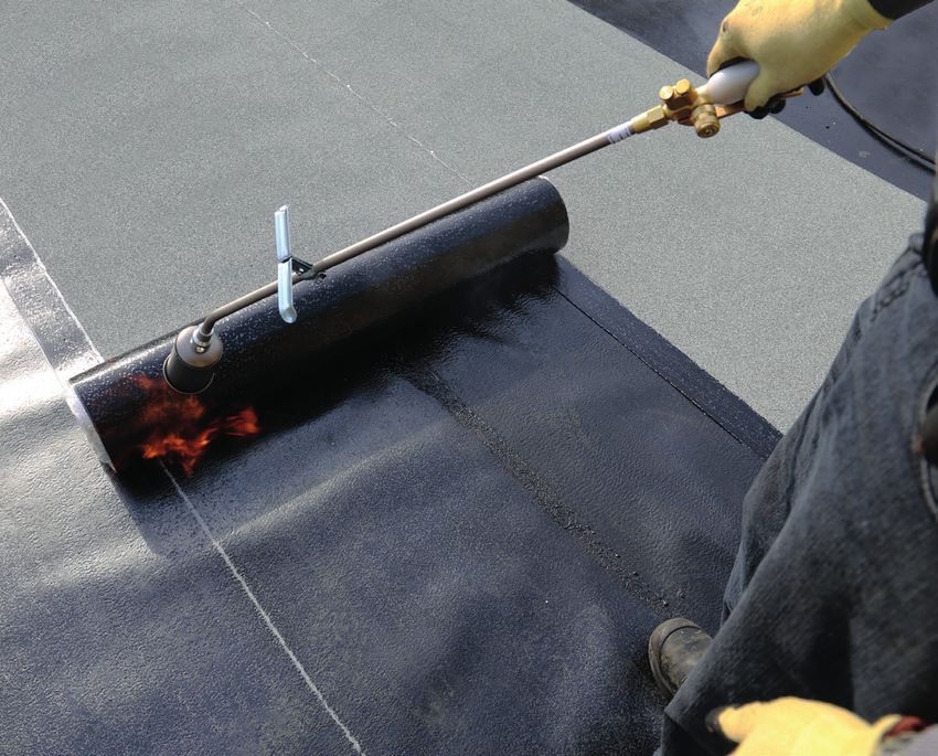
2.1. HEAT-WELDED MEMBRANES
Heat-welded membranes are preferred due to their efficiency
when it comes to installation temperatures and site conditions.
Of course, the use of a propane torch, with the benefits of
facilitating installation in cold weather, requires careful handling
to ensure the safety of installers and residents alike, as well as
the integrity of the building.
In all cases, the contractor must identify the areas at risk before
the start of the project and provide safe solutions.
For safety reasons, heat-welded membranes must never be
installed directly on wood or near combustible products or
substrates.
Non-combustible cover panels, such as asphaltic or mineral fibre
(rockwool) panels with bituminous surface, as well as flame
shields, must be used to prevent the flame from directly touching
the wooden substrate.
252.1.1. Limitations
There is no temperature limit for heat-welded membranes. This
is why they can be installed efficiently even in winter conditions.
However, in very cold weather, some special work methods are
recommended to ease their installation.
It is recommended to use a safe device complying with the
applicable standards to keep the propane tank at the required
temperature.
Using the torch, slightly heat the last two metres of the cap sheet
membranes near the mandrel. This operation reduces the tension
inherent in the reinforcement.
Do not re-roll the membrane as tight as you would during the
summer. The last two metres of the membrane will be easier to
weld if it is rolled more loosely.
2.1.2. Conditioning of Membranes
It is recommended to completely unroll the membrane 10 to 15
minutes before the installation, regardless of the temperature.
This procedure releases the tension accumulated in the
membrane during manufacturing and eases the application for
the installer.
When the temperature is below 0 °C, it is recommended to burn
the plastic film of the upper face of the base sheet in a zigzag
pattern (Figure 8).
It is not required to burn the plastic film from the underside
of the cap sheet membranes. However, in cold weather, some
installers prefer to perform this operation to ease the welding of
the membrane.
Note: Adhesive tapes used to
keep membranes rolled-up must
be removed from all membranes
before they are installed.
Otherwise, it may compromise
adhesion and cause blistering.
Adhesive tape also emits toxic
fumes if exposed to a torch flame.2021 ROOFER’S GUIDE BITUMINOUS
2020 ROOFER’S
MEMBRANES
GUIDE
2.1.3. Installation Methods
2.1.3.1.Horizontalroofsurface
Maintain the appropriate distance
between the end of the torch head
and the roll. This distance varies
from approximately 150 to 305 mm,
depending on surrounding conditions
(Figure 4). This distance must be
maintained to get the maximum heat
and proper diffusion of the flame.
Figure 4
Before beginning to weld, pay special attention to the
following points:
Know the product you are welding: its thickness, reinforcement,
and type of underface (sanded or polypropylene foil).
Know the type of material to which you are welding this product:
directly to concrete, to another membrane, or to a board that can
be welded to.
Take into consideration the weather conditions. The speed
of welding depends on the temperature, humidity and wind
conditions. Propane consumption is also affected by these
elements.
Welding speed decreases in cold, humid weather, and increases
in hot, dry weather. The speed may even vary over the course
of a day. To control these differences, just perform a few tests
when you are ready to install the first roll, or whenever conditions
change (for example, heat the roll over a few centimetres, stop,
back-roll the roll, check the uniformity of the weld and adjust
your pace based on the results).
The weld will be more effective if the movement of the torch, and
hence its flame, is continuous and even, in a rectangular pattern
(Figure 5).
The torch head position shown is recommended for obtaining the
best welding technique.
Figure 5
27Never point the flame (torch head inverted) between the two
layers. This may trap air and cause fishmouths or wrinkles in the
layer (Figure 6).
Risk of blisters or ridges
Figure 6
For best results, make sure there is always a small string of
melted bitumen in front of the roll being installed (Figure 7).
When in doubt, re-roll the roll – “hairs” of bitumen should appear
across the length of the roll.
Figure 7
Always unroll membranes in a continuous fashion. Starting and
stopping mid-roll may cause slight undulations in the surface.
Along the side lap, keep the flame pointed towards the inside of
the roll to prevent burning of the granulated surface.
It is recommended to create a bleed out of 3 to 6 mm to visually
confirm membranes are waterproof. For aesthetic reasons, when
there is excessive bleed out on cap sheet membranes, you may
cover it with bulk granules.
Why and How to Embed Granules?
Why?
The purpose of embedding granules is to prepare the overlapping
joint for the next cap sheet membrane. This operation is not
only recommended but MANDATORY because the embedding
of the granules guarantees a suitable weld at these critical
spots. Embedding the granules will provide bitumen-to-bitumen
adhesion. If the granules are not embedded, the bond or weld
could be inadequate and may even cause peeling.
How?
To embed the granules, heat the granulated surface with a torch
to soften the bitumen. When the bitumen becomes shiny and
the granules begin to sink slightly, stop heating and embed the
granules in the bitumen using a trowel. A hot trowel will slide
easily and prevent granules from sticking to it.2021 ROOFER’S GUIDE BITUMINOUS MEMBRANES
In some cases, a specifically designed granule embedder can be
used.
Note : It is important to embed the granules
by sliding the trowel over the surface and
not to scrape off the granules and bitumen.
Always keep your trowel clean.
2.1.3.2. Flashings
Important safety notes:
Take extra caution when membranes are welded near
combustible substrates such as plywood.
Install a fire-stop membrane wherever flames can enter.
Never use the torch on a surface where a solvent-based
product has been freshly applied (wait for it to dry).
Do not torch on enclosed surfaces, such as underneath air
conditioning units or behind counter flashings.
Voids, holes or gaps in or near the substrate have to also be
protected to prevent flame penetration.
Make sure that there is no ventilation or negative pressure to
attract or fan the flame.
Weld the membrane over the flashings using the method shown
on the next page.
29Check the dimensions and adjust as Torch corner. required. Press into corner. Torch upwards. Torch overlap. Torching completed. 2.2. SELF-ADHESIVE MEMBRANES Self-adhesive membranes are ideal for projects where the use of the flame is not permitted or desired. This type of installation is well adapted to the particular needs of construction sites where safety is paramount, like schools and hospitals. These membranes are bonded in full adhesion or in semi- adhesion(COLVENT), with or without primer depending on the type of product and substrate. Self-adhesive base sheet membranes can also be used in conjunction with heat-welded cap sheet membranes. This hybrid method optimizes fire safety on construction sites while offering the benefits of heat-welded membranes. It is also possible to match sanded self-adhesive base sheet membranes with self-adhesive cap sheets or cap sheet membranes bonded with adhesive.
2021 ROOFER’S GUIDE BITUMINOUS
                                  2020 ROOFER’S
                                          MEMBRANES
                                                GUIDE

   2.2.1. Limitations
Self-adhesive sheet membranes could be affected by poor
ventilation when they are installed directly to a wooden deck
with ventilated attic space. Since it is impossible to predict
temperatures at which membranes will be exposed in these
conditions, it is recommended to mechanically fasten the
membranes. This can be done by using compatible fastening
systems.
When a flameless roof system is required or desired, all welding
including that of the side and end lap joints, must be completed
with an electric hot air welder and a membrane roller or an
automatic hot air welder.
When the parapet exceeds 1 meter in height, a first row of
fasteners must be installed and spaced at a maximum distance
of 600 mm on center. Depending on the height of the parapet,
an additional staggered row of fasteners must be installed every
other 600 mm. It is not necessary to cover these fasteners with a
reinforcing membrane but it can be done as an option.
If the parapet is not covered with a metal cap flashing, secure
the top of the base sheet membrane with compatible fastening
systems spaced 300 mm on center.

   2.2.2. Conditioning of Membranes
It is recommended to completely unroll the membrane 10 to 15
minutes before the installation, regardless of the temperature.
This procedure releases the tension accumulated in the
membrane during manufacturing and eases the application for
the installer.
When the temperature is below 10 °C, burn the plastic film of the
upper face of the base sheet in a zigzag pattern (Figure 8).

Figure 8

                                                                    31
2020 ROOFER’S GUIDE
2.2.3. Installation Methods
2.2.3.1. Horizontal roof surface
Cover the substrate surface with primer for self-adhesive
membranes.
Install the membrane according to its type of silicone release
film.
Simple silicone release films:
Peel off a corner of the silicone film to allow the membrane
to adhere to the surface. Then remove the silicone paper at
an angle of 45°. While one worker peels off the silicone paper
from the underface of the membrane, the other should pull on
its free end to prevent creating any wrinkles in the membrane.
Apply pressure over the whole surface using a heavy membrane
roller to ensure a complete and uniform adhesion.
Split-back silicone release films:
Fold one half of the roll lengthwise on the other half. Peel the
film, fold the exposed half over the base sheet, first by the
centre, then by the two ends (butterfly technique) and repeat
for the second half. It is best to have at least two workers to
perform this manoeuvre.
Apply pressure over the whole surface using a heavy membrane
roller to ensure a complete and uniform adhesion.
Process for end laps of fully adhered base sheet
membranes:
For membranes with sanded surface, when completing end
lap, apply ELASTOCOL STICK primer over the last 150 mm of
the membrane before installing the next membrane.
For membranes with weldable surface, when completing
end lap, burn the plastic film over the last 150 mm of the
membrane before installing the next membrane.
Process for end laps of cap sheet membranes:
For the cap sheet membrane, apply cold adhesive on the first
100 to 125 mm of the end laps and weld the last 25 to 50 mm
using a hot air welder.
Finish the application by welding the last 25 mm of the DUO
SELVEDGE side laps using a hot air welder.
The use of SOPRAMATIC or automatic hot-air welder will
increase the speed and quality of the welding.
2.2.3.2. Flashings
Cover the substrate with primer for self-adhesive membranes.
Peel off the silicone release paper at a 45° angle so as not to
create any wrinkles in the membrane.
Apply pressure as the protective film is peeled off using an
aluminum applicator or a membrane roller to obtain full
adhesion.
Apply adhesive on the first 100 to 125 mm of the end laps with
notched trowel.
322021 ROOFER’S GUIDE BITUMINOUS MEMBRANES
Finish the application by welding the last 25 to 50 mm of the end
lap and the DUO SELVEDGE side laps.
Note: It is mandatory to use a membrane roller to
optimize the adhesion of the membranes.
2.3. MECHANICALLY FASTENED MEMBRANES
Base sheet membranes are attached to the deck with mechanical
fasteners, as this method increases the installation speed
of the roof assembly and does not require support panels.
These systems are used for large areas and where wind uplift
resistance may be high.
2.3.1. Limitations
On a steel deck, mechanical fasteners must be installed on the
upper part of the ribs so that the fastening line is perpendicular
to the ribs.
Mechanical fasteners should be installed on the insulation boards
at the rate of four fasteners minimum for a 1.2 × 1.2 m board and
six fasteners minimum for a 1.2 × 2.4 m board. More fasteners
may be required depending on the results of the wind uplift
resistance test.
2.3.2. Conditioning of Membranes
It is recommended to completely unroll the membrane 10 to 15
minutes before the installation, regardless of the temperature.
This procedure releases the tension accumulated in the
membrane during manufacturing and eases the application for
the installer.
When the temperature is below 10 °C, burn the plastic film of the
upper face of the base sheet in a zigzag pattern (Figure 8).
2.3.3. Installation Methods
2.3.3.1. Horizontal roof surfaces
Fasten the end of the membrane.
Pull firmly on the whole length of the roll and fasten the
membrane along the side joint, starting from the free end and
moving towards the fastened end.
Mechanical fasteners must be installed in the centre of the side
lap of the membranes aligned with the marks drawn along the
overlap and according to the specified fastening pattern.
When installed on insulated panels, apply sufficient pressure on
the screws and plates while making sure not to change the levels
of the membranes by screwing them in too deeply.
Weld the last part of the DUO SELVEDGE with a propane torch or
a SOPRAMATIC electric hot air cart.2020 ROOFER’S GUIDE
2.3.4.2. Flashings
Installing mechanically-fastened flashing membranes is not
allowed. Refer to the other installation methods provided in this
guide.
2.4. MEMBRANES BONDED WITH COLD ADHESIVE
Membranes installed with adhesives are ideal for projects where
the use of a flame is not permitted or desired. This type of
installation is well adapted to the particular needs of construction
sites where safety is paramount, like schools and hospitals.
SOPREMA offers three technologies of adhesive for membrane,
each with their own particularities regarding handling, limitations,
and application temperatures.
SOPREMA also offers adhesive-bonded membranes specifically
designed for low temperature applications. These are easier to
handle at temperature as low as -10 °C.
Contact your local SOPREMA representative for more
information.
2.4.1. Limitations
When a flameless roof system is required or desired, all welding,
including that of the side and end lap joints, must be completed
with an electric hot air welder and membrane roller or a
SOPRAMATIC or hot air blower cart.
In order to prevent moisture on sanded surfaces, it is
recommended to install the cap sheet membrane on the same
day as the base sheet membrane. If same-day installation is
impossible, saturate the sanded surface with ANTIROCK primer
This will help the surface to dry when works resume.
The cold-applied adhesives that contain solvents can damage
polystyrene insulation. SOPREMA therefore does not recommend
using a system with membranes bonded with this type of
adhesive if the roofing system includes polystyrene insulation.
This includes protected membrane roofing systems.
The use of a solvent-based adhesive is not permitted to bond
membranes over coated or uncoated rockwool insulation.
It is not recommended to use a cold-adhesive-bonded membrane
for lightweight insulated concrete systems.
Cold adhesives should not be used to bond rubber mats.
2.4.2. Conditioning of Membranes
It is recommended to completely unroll the membrane 10 to 15
minutes before the installation, regardless of the temperature.
This procedure releases the tension accumulated in the
membrane during manufacturing and eases the application for
the installer.
For the application techniques, curing times and coverage rate of
each adhesive, consult the respective technical data sheets.
342021 ROOFER’S GUIDE BITUMINOUS MEMBRANES
2.4.3. Installation Methods
2.4.3.1. Horizontal roof surfaces
Unroll the membrane dry on the support.
Re-roll and spread adhesive using a notched squeegee on the
surface to be bonded. Note that the coverage rate may vary
depending on the substrate condition.
Unroll the membrane on the adhesive and apply pressure over
the whole surface using a heavy membrane roller to ensure
complete and uniform adhesion.
Apply adhesive on the first 100 to 125 mm of the end laps with a
notched trowel.
Finish the application by welding the last 25 to 50 mm of the end
laps. Welding must also be done on all side laps.
The use of SOPRAMATIC or automatic hot-air welder will
increase the speed and quality of the sealing.
2.4.3.2. Flashings
Note: For flashing membranes, although it is
possible to use two layers of membrane bonded
with adhesive, SOPREMA recommends using a self-
adhesive base sheet and cap sheet to facilitate the
application of the membranes.
2.4.3.2.1. Method No. 1
Coat the surface of the substrate with adhesive using a notched
trowel. Leave 25 to 50 mm free of adhesive at end and side laps.
Lay the membrane on the adhesive.
Partially weld the bottom of the membrane to hold it in place.
Apply pressure over the entire surface with a membrane roller to
obtain complete and uniform adhesion.
For the base sheet membrane only, if the substrate is plywood,
secure the membrane at the top of the parapet with round
top nails spaced every 305 mm on centre. For other types of
substrate, use an alternative fastening method.
Finish the application by welding the last 25 to 50 mm of the end
and side laps.2.4.3.2.2. Method No. 2
Coat the underface of the membrane AND the surface of the
substrate with adhesive using a notched trowel. Leave 25 to 50 mm
free of adhesive at transverse and longitudinal overlaps.
Wait 10 minutes, then lay the membrane on the substrate.
Partially weld the bottom of the membrane to hold it in place.
Once the membrane is placed on the adhesive, apply pressure
over the entire surface with a roller to obtain complete and
uniform adhesion.
Finish the application by welding the last 25 to 50 mm of the end
and side laps.
2.4.3.2.3. Method No. 3
Note: In order to prevent the membranes from peeling
off at transitions, a two-piece installation of membranes
is strongly recommended when the temperature is
below 0 °C.
Coat the surface of the substrate with adhesive using a notched
trowel.
All last 25 to 50 mm of the end laps and side laps on base sheets,
as well as cap sheet, must be free of adhesive so they can be
welded following the first stages regarding the installation of the
membrane.
Install the first piece of membrane on the adhesive. Make sure
the top end lap of the membrane is aligned with the upper inside
corner of the parapet.
Partially weld the bottom of the membrane to hold it in place
and weld the last 25 to 50 mm of membrane at the top of the
parapet.
Install the second piece of membrane on the top of the parapet.
The membrane must exceed at least 50 mm on either side of the
parapet.
Weld the first 50 mm flap located on the inside of the parapet
and stretch the membrane over the parapet to fix the other end
using mechanical fasteners.
Apply adhesive on the surface of the base sheet using a notched
trowel without covering the top of the parapet.
Install the cap sheet on the adhesive by planning to fold the
membrane at least 50 mm over the top of the parapet.
Partially weld the bottom of the membrane to hold it in place and
weld the 25 to 50 mm located on the top of the parapet and the
50 mm on the horizontal.
Apply pressure throughout the entire on the full surface using a
membrane roller to optimize the adhesion of the membranes.
Cover the top of the parapet with an adhered piece of cap sheet
membrane or a metal cap flashing.2021 ROOFER’S GUIDE BITUMINOUS
2020 ROOFER’S
MEMBRANES
GUIDE
2.5. FACTORY-LAMINATED BASE SHEET BOARDS
Factory-laminated base sheet boards (2-in-1 and 3-in-1) allow
the installer to quickly waterproof the roof, thus protecting the
system components from the weather in a very short time.
In addition, since the membrane is already factory-laminated
on the support panel, the boards can be installed without
temperature limitation.
With the DUO SELVEDGE technology, sealing the first self-
adhesive section of the joint helps to protect the components
under the base sheet from flame. The rest of the selvedge
surface is then safely welded with a torch, a hot-air welder, or
using the SOPRAMATIC.
2.5.1. Limitations
There is no temperature limit for the installation of factory-
laminated base sheet boards. These can be installed effectively
even in winter conditions.
When boards are mechanically fastened on a system with
insulation, apply sufficient pressure on the screws and plates
while making sure not to cause a level change of the membranes
by screwing them in too deeply.
2.5.2. Conditioning of the Panels
All 2-in-1 and 3-in-1 panels must be stored on a flat surface and
protected from UV rays and harsh weather.
Never install boards that show signs of moisture.
2.5.3. Installation Methods
2.5.3.1. Horizontal roof surface
All panels must be perfectly aligned without any significant
height difference between them.
Bonded with DUOTACK adhesives
Adhere the base sheet boards with beads of
adhesive applied according to the spacing
specified in the wind uplift external test
reports, ensuring that the pattern chosen
meets the required wind uplift resistance for
the building.
37Mechanically fastened
Laminated boards should be installed perpendicularly to the steel
deck flutes.
Mechanical fasteners must be installed at the centre of the
selvedges of the membranes.
Screws and plates must be installed as indicated in the wind
uplift test reports.
Seal the DUO SELVEDGE side lap joints with a torch and round-
nosed trowel or a hot-air welder and a membrane roller.
2.5.3.2. Flashings
Mechanically fasten the composite panel with screws and plates
or round top nails to the parapet substrate.
When the laminated board has a sanded surface:
Apply a coat of ELASTOCOL STICK primer on a 100 mm width,
centred on every angle changes. Install a 150 mm self-adhesive
reinforcement membrane centred on each angle change and
weld the last 25 mm on each side.
When the laminated board has a weldable surface:
Weld a 150 mm reinforcement membrane centred on each
angle change.
Continue with the installation of the cap sheet following the
recommendations for the type of membrane used.2021 ROOFER’S GUIDE BITUMINOUS MEMBRANES
3.0.
INSULATION
INSTALLATION
METHODS3.0. INSULATION INSTALLATION METHODS
The insulation technologies offered by SOPREMA help maintain
a comfortable temperature inside buildings while increasing their
energy efficiency.
SOPREMA offers different types of roof insulation. The choice
of insulation and its installation method is based on the
characteristics and limitations of each.
Insulation panels made of polyisocyanurate foam and rock
fibres are used in self-protected cap sheet membrane systems
(conventional) and extruded polystyrene insulation boards are
generally used in protected membrane roof systems (inverted).
Polyisocyanurate panels and extruded polystyrene panels are
available with shiplap edges, allowing a single row of insulation to
be installed without having to worry about offsetting panel joints.
This also saves time on the site as the installation is completed
faster.
3.1. GENERAL INFORMATION
Insulation boards are installed in staggered rows. If the
installation of the insulation boards can’t be completed the same
day, the site organization must allow staggered installation to
resume.
When upstands are insulated from the outside, use a cover panel
before installing the membrane.
When the insulation boards are mechanically fastened, use
screws and plates specially designed for insulation.
3.2. STORAGE
The insulation boards are typically protected by a plastic film for
handling and transportation. However, this film does not provide
adequate protection for long-term storage on a worksite.
To limit the storage period on site, schedule delivery a little before
the board installation date.
Follow these precautions when on-site storage is required (on the
ground or the roof):
Store pallets flat on a finished surface (gravel, pavement,
concrete, etc.) rather than on a surface that can remain wet
(grass, soil, etc.), and ensure they are elevated by at least
75 mm.
Cover the pallets with waterproof tarps and shelter them
from the wind.
402021 ROOFER’S GUIDE BITUMINOUS MEMBRANES
3.3. POLYISOCYANURATE BOARDS
Polyisocyanurate boards are
offered with organic facers
reinforced with glass fibers or
with polymers coated glass fibers
facers.
3.3.1 Limitations
Polyisocyanurate boards of 1.2 m × 2.4 m must not be bonded
with hot bitumen or adhesive.
Where a base sheet is mechanically fastened, mechanical
fasteners must be installed on the insulation board using a
minimum of four fasteners for each 1.2 m × 1.2 m panel and six
fasteners for each 1.2 m × 2.4 m panel. More fasteners may be
required depending on the wind-resistance.
3.3.2. Installation Methods
Mechanically fastened with screws and plates designed
for insulation.
Bonded with DUOTACK or DUOTACK 365 adhesives.
3.4. ROCKWOOL BOARDS
Rockwool boards are available
with or without bitumen-coated
surface. The bitumen layer is used
to install membranes using hot
bitumen or adhesive, or to weld
them directly onto the insulation
boards.
3.4.1. Limitations
Self-adhesive membranes must not be installed on this type of
board, whether they have a bitumen-coated surface or not.
No adhesive, including hot bitumen, can be applied to the surface
of an uncoated rock wool panel.
When an uncoated rockwool panel is mechanically fastened,
at least one of the elements installed on it must also be
mechanically fixed.
The only way to install an element on an uncoated rockwool
panel is to mechanically attach it. As a result, the rockwool panel
is fastened at the same time.
3.4.2. Installation Methods
Mechanically fastened with screws and plates designed
for insulation.
Bonded with hot bitumen.
Bonded with DUOTACK or DUOTACK 365 adhesives.
Loose laid.2020 ROOFER’S GUIDE
3.5. EXTRUDED POLYSTYRENE BOARDS
3.5.1. Limitations
Extruded polystyrene boards must be covered with a
polyisocyanurate or mineral fibres (rockwool) board of a minimum
thickness of 50 mm. This rule does not apply to the use of
extruded polystyrene on an inverted roof system.
The use of materials bonded with hot bitumen is not
recommended in a waterproofing system using extruded
polystyrene insulation boards. These materials include insulation
boards, support panels and base sheet membranes.
The cold-applied adhesives that contain solvents can damage
polystyrene insulation. SOPREMA therefore does not recommend
using a system with membranes bonded with this type of
adhesive if the roofing system includes polystyrene insulation.
This includes protected membrane roofing systems.
Do not install extruded polystyrene boards if they can’t be
covered the same day.
3.5.2. Installation Methods
Mechanically fastened with screws and plates designed
for insulation.
Bonded with DUOTACK adhesives.
Loose laid
When a polystyrene board is used on a protected membranes
roof, it is installed loose laid on the roof. The ballast placed on
the roof keeps the boards in place. Install a filter cloth or an open-
diffusion drainage board over the polystyrene panels.
422021 ROOFER’S GUIDE BITUMINOUS MEMBRANES
4.0.
SUPPORT PANELS
INSTALLATION
METHODS4.0. SUPPORT PANELS INSTALLATION METHODS
Support panels are used in most roofing systems with bonded
membranes. They provide additional stability to the roof system
as well as better resistance to fire, hail, wind, mildew, and
compression depending on the type of panel. It is therefore
important to choose the right support panel according to the
needs and requirements of the project.
4.1. LIMITATIONS
Support panels must be quickly covered after their installation
and can’t be left exposed to the weather.
Support panels are installed in staggered rows. If the panel
installation can’t be completed the same day, the site
organization must allow staggered installation to resume.
4.2. STORAGE
Some support panels are protected by a plastic film for handling
and transportation. However, this film does not provide adequate
protection for long-term storage on a worksite.
To limit the storage period on site, schedule delivery a little
before the installation date of the support panels.
Respect the following precautions when on-site storage is
required (on the ground or the roof ):
Store pallets flat on a finished surface (gravel, pavement,
concrete, etc.) rather than on a surface that can remain wet
(grass, soil, etc.), and ensure they are elevated by at least
75 mm.
Cover the pallets with waterproof tarps and shelter them
from the wind.
4.3. ASPHALTIC PANELS
4.3.1. Installation Methods
Mechanically fastened with screws and plates designed
for insulation.
Bonded with DUOTACK adhesives.
442021 ROOFER’S GUIDE BITUMINOUS MEMBRANES
4.4. HIGH DENSITY POLYISOCYANURATE BOARDS
4.4.1. Installation Methods
Mechanically fastened with screws and plates designed
for insulation.
Bonded with DUOTACK adhesives.
4.5. WOOD FIBRE
4.5.1. Installation Methods
Mechanically fastened with screws and plates designed
for insulation.
Bonded with DUOTACK adhesives.
4.6. PERLITE
4.6.1. Installation Methods
Mechanically fastened with screws and plates designed
for insulation.You can also read