A Guide to the Australian Playground Standards - by Andrew Reedy (January 2021)
←
→
Page content transcription
If your browser does not render page correctly, please read the page content below
A Guide to the Australian
             Playground Standards
                                              by Andrew Reedy

                                                    (January 2021)

PO Box 5063 Canning Vale South   P | 08 9256 1441      E | andrew@playcheck.com.au
Western Australia 6155           M | 0417 971 102      W | www.playcheck.com.au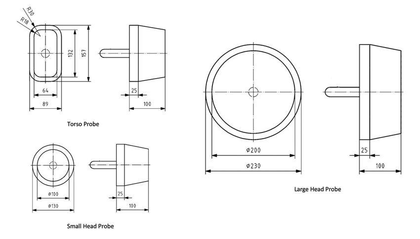
A Guide to the Australian Playground Standards

                                              Index
Introduction                                                                                      2
A playground defined                                                                              3
Natural elements in a playground                                                                  3
Risk-benefit assessment                                                                           3
Equipment not meeting current standards                                                           4
Inspection regimes                                                                                4
Categories of playground equipment                                                                6
Free height of fall                                                                               6
Surfacing requirements                                                                            10
Impact area, falling space and free space                                                         10
        Impact area                                                                               11
        Falling space                                                                             15
        Free space                                                                                15
Protection against falling                                                                        16
       Handrails                                                                                  16
       Guardrails                                                                                 17
       Barriers                                                                                   17
       Openings in barriers                                                                       18
       Grip & grasp                                                                               19
Protection against entrapment                                                                     20
       Head/neck entrapment – completely bound openings                                           20
       Head/neck entrapment – partially bound and V-shaped openings                               21
       Head/neck entrapment – non-rigid or flexible openings                                      23
       Clothing entrapment                                                                        23
       Entrapment of the whole body                                                               24
       Foot and leg entrapment                                                                    25
       Finger entrapment                                                                          25
Protrusions and finish of equipment                                                               26
Moving parts                                                                                      27
Means of easy access (ladders, stairs & ramps)                                                    27
Specific requirements for Swings                                                                  28
Specific requirements for Slides                                                                  29
Foundations                                                                                       30
Equipment identification and marking                                                              30
Supervised Early Childhood (specific requirements)                                                30

          A Guide to the Australian Playground Standards (written by Andrew Reedy – Play Check)   Page 1 of 30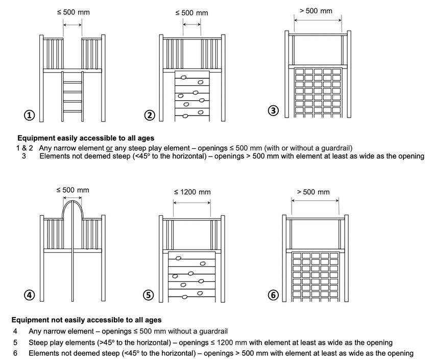
A Guide to the Australian Playground Standards

Introduction
The Standards are, by nature, a technical document and are not necessarily organised in a format or sequence
that makes them easy to follow without significant cross referencing. Even those who spend much time working
with these Standards often find themselves searching the various parts of the standard for an obscure clause that
impacts the way other clauses are interpreted in a particular application. The aim of this guide is to organise the
information contained in the Australian playground Standards under logical and sequential headings. For
example, when determining the Free Height of Fall for each item of equipment in a playground it is necessary to
go through each of the individual parts of the Standards to find the height requirements for various types of
equipment. This guide collates the Free Height of Fall requirements for all types of equipment under one heading
for easy reference.
The Standards applicable to playgrounds and referenced in this document are as follows:
            •   AS 4685.0:2017 – Playground equipment and surfacing – Development, installation, inspection,
                maintenance and operation
            •   AS 4685.1-6: 2021 (6 parts) – Playground equipment – General safety requirements and test
                methods + Additional specific requirements for swings; slides; runways; carousels; rocking
                equipment
            •   AS 4685.11:2012 – Playground equipment – Additional specific safety requirements and test
                methods for spatial networks
            •   AS 4422:2016 – Playground surfacing – Specifications, requirements and test method
This document does not replace the need to use or rely on the actual Standard documents, which contain detail
not included in this guide. In particular, designers and manufacturers of play equipment need to be aware of all
aspects and detail covered in the Standards. This guide does however provide a ready reference for many of the
commonly sought elements of the playground Standards. Any opinions expressed in this document are those of
the author and should not be construed to be those of Standards Australia.
Various aspects of the Standard are still open to interpretation and it should be understood that Standards serve
as a guide. The Standards play an important part in the risk assessment and management of play provision,
however treating them as a single or absolute requirement can lead to disproportionate and expensive corrective
responses to minor issues or failures, which have minimal influence on safety.

About Play Check
Director of Play Check, Andrew Reedy, has been involved in the playground industry
since 1994. During this time, he has been involved in the design and manufacture of
playground equipment, as well all aspects of safety and compliance.
Since 2002 he has been a member of the Standards Australia committee for
playground equipment (CS-005) and has been involved in the development all
versions of AS 4685, as well as AS 4422:2016.
Andrew has represented Standards Australia on the ISO (International Standards
Organisation) technical committee for playgrounds (TG 83 / WG8). He is also a member of CS-101, which deals
with Standards including outdoor exercise equipment and parkour.
Play Check specialises in providing advice and auditing services to all sectors of the playground industry, in terms
of playground design, safety, risk assessment and surface impact attenuation testing.

                          A Guide to the Australian Playground Standards (written by Andrew Reedy – Play Check)   Page 2 of 30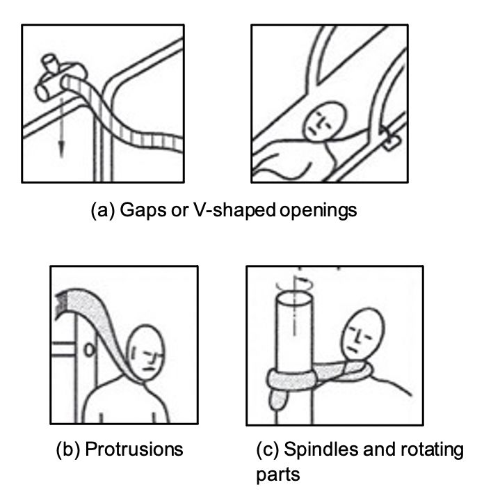
A playground defined
A playground is defined as an area designed for children’s play, including the site, natural features, built
landscape, and any manufactured equipment and surfacing.
The playground Standards do not include fitness equipment unless these items are integrated into the playground
along with other play equipment. Outdoor fitness equipment is covered under a separate Standard, AS
16630:2020. The playground Standards do not apply to domestic playgrounds or sporting equipment.

Natural elements in a playground
Natural elements incorporated into playgrounds are inherently diverse and open-ended, and many offer the
benefit that children can manipulate them for their own play purposes. Such nature-based play environments can
help build creativity, imagination, and problem-solving skills. Access to nature has been shown to improve
children’s psychological wellbeing and encourage stewardship of the environment.
Unlike manufactured products and materials, natural elements are not necessarily predictable. They therefore
encourage children to develop risk management skills as they negotiate natural environments and build resilience
through exposure to falls and minor injuries as they learn to adapt their behaviour to the setting.
The requirements of the Standards do apply to natural play elements incorporated into a playground. Where the
requirements of the Standard cannot sensibly be applied to natural elements, a risk benefit assessment should be
undertaken and documented to determine the suitability of such elements. This risk assessment should take into
account the basic principles of injury prevention that underlie the AS 4685 series of Standards.
        Example of considerations in a risk assessment:
        It may not be practical or desirable to place barriers or handrails on a log or boulder (which could be construed as platforms under
        the definition in the Standard). In this instance, while handrails or barriers may not be used, the following considerations would be
        taken into account: impact-attenuated surfacing, in accordance with AS 4422:2016, should be provided in the impact area
        corresponding to the free height of fall; the impact area should be free of obstacles that could cause injury; hazardous situations
        that may cause entrapment (e.g. a forked branch that could create an entrapment hazard) should be avoided; and sharp
        protrusions should be removed. Consideration should also be given to preventing easy access to higher parts or potentially
        hazardous situations.

It is important to recognise the value to children of engaging with nature. The incorporation of natural materials
as design elements in a playground can add significant play, aesthetic and environmental value.

Risk-benefit assessment
At times, certain elements in a playground may not comply strictly with one or more of the requirements of the
playground Standards. Whether in the case of older equipment not meeting current Standards, or newer
equipment that deviates from the Standards in some way, a risk assessment should be conducted to determine
whether the deviation is acceptable or whether remedial action should be undertaken.
A standard risk assessment involves the identification, evaluation, and estimation of the levels of risk involved in
each particular situation and the likelihood of its occurrence, its comparison against benchmarks or standards,
and determination of an acceptable level of risk.
The use of a risk-benefit assessment incorporates the value or benefit of the activity into this equation. A risk-
benefit assessment explicitly brings together consideration of the benefits as well as the risks of play in a single
judgement. Risk-benefit assessments are covered in AS 4685.0 and have been shown to be a valuable tool in
determining an acceptable level of risk.

                              A Guide to the Australian Playground Standards (written by Andrew Reedy – Play Check)            Page 3 of 30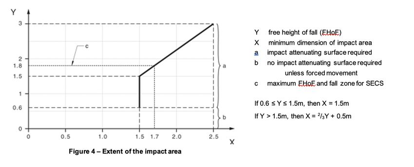
Equipment not meeting current standards
Playground inspectors with the skills and competencies to conduct such inspections should carry out regular risk
assessments. When assessing old equipment that may not comply with all of the requirements of current
Standards, the following steps should be taken:
    1. Assess areas of non-compliance against the Standard that was applicable when the playground was
       installed and against current requirements that may have safety implications.
    2. Determine level of risk of non-compliant items (risk/benefit assessment).
    3. Determine whether there is a need for replacement or upgrade based on the risk/benefit assessment or
       whether the equipment is acceptable.
    4. If replacement is required, determine a time frame based on the level of risk.

Inspection regimes
The following types and frequency of playground inspection are recommended in the Standards.

Playgrounds (excluding under-surfacing)
    •   Comprehensive post-installation inspection.
        - This may not be required on every installation. Simple items, e.g. swings, and other basic equipment
           may be easily assessed for compliance by the operator (if their level of understanding of Standards is
           sufficient) and may not require independent assessment.
    •   Comprehensive annual inspection.
        - Annually.
    •   Operational inspection.
        - Generally quarterly, but may vary depending on local circumstances.
    •   Routine visual inspection.
        - Frequency to be determined depending on local circumstances.

Playground impact attenuation surfacing
Unitary surfacing (e.g. rubber or synthetic grass)
    • A post-installation inspection is required in accordance with the requirements of AS 4422:2016.
    • Subsequently, unitary surfacing should be tested at least every 3 years.
Loose-fill surfacing (e.g. sand, wood-chip, mulch)
    • Loose-fill surfaces need not be impact attenuation tested on a regular basis providing:
      1. the generic product typically complies with the requirements of AS 4422:2016 when tested; and
      2. the material is installed to a minimum depth of 300mm and is maintained to a depth of at least 200mm.

Competence of persons performing inspections
The person performing each of the inspections should have acquired through training qualifications or experience
or a combination of these, the knowledge and skills enabling them to perform inspections at the various levels.

                          A Guide to the Australian Playground Standards (written by Andrew Reedy – Play Check)   Page 4 of 30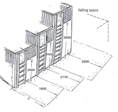
Routine Visual Inspections
Routine visual inspections are intended to identify obvious hazards that can result from wear and tear, vandalism
or weather conditions. Any potentially hazardous situations shall be reported immediately and/or rectified.
Routine visual inspections should include:
            q Checking for and removal of debris in the playground that may be hazardous, such as broken glass or
              needles.
            q Checking that loose-fill surfacing levels are maintained at a depth of between 200 mm and 300 mm.
            q Checking for damage to unitary surfacing.
            q Checking for equipment that is broken or missing as a result of use or vandalism.
            q Checking for graffiti.
            q Checking the condition of ancillary items, such as barbecues, tables rubbish bins, etc.
            q Checking for dead overhanging branches that may potentially fall onto the playground.

Operational Inspections
Operational inspections primarily focus on items that may be affected by use and wear. They should include:
            q All issues listed in Routine Visual Inspections.
            q Checking for excessive wear of moving parts (including chain links).
            q Ensuring that bolts and fasteners are secure.
            q Checking for any protrusions and sharp edges that occur as a result of damage or wear.
            q Checking the stability of all playground equipment including ancillary items. Equipment that relies on a
              single post, anchor or attachment point should be carefully inspected.
            q Checking for excessive corrosion, particularly within structural members.
            q Checking wire ropes for fraying.
            q Check seat/ground clearance cableway.
            q Check for damage to impact and attenuating edges of swing seats, pommels and other moving
              equipment that can impact users.
            q Check clearances beneath carousels (where the clearance may vary over time).
            q Checking foundations are adequately covered.

Comprehensive Annual Inspections
A comprehensive inspection is intended to establish the overall level of safety of the equipment, foundations and
playground surfaces. This inspection includes an assessment of elements that can degrade over time.
Examples of factors that should be included in a checklist when conducting comprehensive inspections are as
follows:
            q Is the surfacing adequate and in good condition?
            q Is the equipment in good repair (i.e. free from excessive rust, cracked welds, splintering timber, etc.)?
            q Is all equipment structurally sound and stable? Equipment that relies on a single anchor or attachment
              point should be given special attention.
            q Are all footings adequately covered?
            q Is the equipment free of protrusions or sharp edges?
            q Is the impact area adequate for the free height of fall?
            q Is the falling space free of obstacles that could cause injury?
            q Is the free space adequate for forced movement items?
            q Are barriers, guardrails and handrails appropriate and at correct heights?
            q Is the equipment free of entrapment hazards?
            q Are all moving parts in good condition and free of excessive wear?

                          A Guide to the Australian Playground Standards (written by Andrew Reedy – Play Check)   Page 5 of 30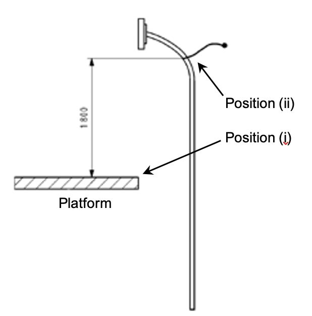
Categories of playground equipment
There are some variations in the requirements of the Standard based on the type of intended use of various types
of equipment. These types of use are separated into the following categories:

Equipment easily accessible to all ages
   •    Defined as requiring only basic skills to access the equipment, allowing users to move freely and quickly
        onto/within the equipment, without further considerations about the use of hands and feet.
                Note: Basics skills should control the ability of a child to use a means of access. If the user needs to
                consider where or how to use their hands and feet when negotiating a means of access, the access
                should generally be considered not easy as it slows down the movement and provides time for
                intervention.
        Some examples of items providing easy access are:
            - Ramps
            - Stairs
            - Ladders, unless the first rung is greater than 400mm above the ground surface.
        (Requirements for ladders, stairs and ramps is found on page 27.)
   •    In such settings a greater level of protection against falling applies.
   •    Steep play elements (defined as access/egress play equipment of a gradient greater than 45o from the
        horizontal) are not permitted at heights above 2000mm on equipment that is ‘easily accessible’ to
        younger children.

Equipment not easily accessible
   •    The equipment design limits the ability to move quickly and freely onto the equipment without further
        considerations about the use of hands and feet. (This delayed access to the equipment gives more time
        for carers to intervene as appropriate.)
   •    In such settings a lower level of protection against falling applies.

Supervised early childhood services (SECS)
    •   A play area used by an education and care service for children under school age, which is supervised by
        educators.
    •    In SECS settings the maximum free height of fall is 1800mm. (See page 30 for other variations.)

Free height of fall
The free height of fall (FHoF) of any component of playground equipment is defined as the greatest vertical
distance from the point of clearly intended body support to the impact area below.
The point of intended body support is also deemed to include those surfaces to which access is encouraged. For
example, some features may provide hand and foot holds for climbing which, taking into account arm or leg reach
distance, make it easy to climb from the intended point of support to a higher point on the equipment. These
examples should not be construed to mean that everywhere to which access may be gained should be deemed as
accessible, as experience has shown that capable climbers can scale almost any item. Consideration should be
given to the ease of access and whether or not the configuration actually encourages access to a higher point on
the equipment.
Table 1 and Figure 1 illustrate the general means of measuring the FHoF. The point of clearly intended body
support for various types of use is generally measured as detailed.
Figure 2 and Table 2 detail specific methods of determining FHoF by equipment type, as well as a guide to
maximum FHoF for each type. The FHoF for some individual items of equipment, particularly where forced
movement is involved, varies as detailed in Figure 2.
In some cases, where forced movement occurs, the surface must have a Critical Fall Height (CFH) which is greater
than the actual fall height of the equipment.

                           A Guide to the Australian Playground Standards (written by Andrew Reedy – Play Check)   Page 6 of 30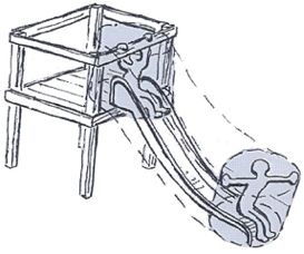
Table 1
Type of use Measurement basis
Standing From foot support to surface below.
Sitting From seat to surface below.
EN 1176-1:2017 (E)
Hanging (when full body support is provided by the hands only) From hand support to surface below.
1:2017 (E)
Dimensions in millimetres
Climbing (body support is a combination of feet/legs and hands) -
From the top of the element to the surface below.
when easy access is provided to the top of theDimensions
element in millimetres
Climbing (body support is a combination of feet/legs and hands) – From maximum hand support (max. 4000 mm) minus 1000 mm, to
when easy access is not provided to the top pf the element surface below.
Note: The reduction of 1000 mm applies when the design of the equipment limits
climbing higher or if there is a sufficient distance to the top to deter climbing higher.
From the suspension bed to the lowest point of falling space, plus
Bouncing
900mm.
EN 1176-1:2017 (E)
a) b)
a) b) Dimensions in millimetres
h
h
h
Hanging
c) d) e)
c) d) e)
Standing Sitting
a) b)
Hanging
f) g)
h c) d) e)
h h
f) g)
ght of fall
Key
h
Figure 14 — Examples showing free height of fall h free height of fall
Figure 14 — Examples showing free height of fall
Climbing (when easy access is Climbing (with sufficient distance Fireman’s poles &
provided to the top) to deter climbing to the top)
climbing ropes
30 f) g)
Key
h free height of fall
h
Figure 14 — Examples showing free height of fall
Bouncing
Figure 1 – General means of determining FHoF
30
A Guide to the Australian Playground Standards (written by Andrew Reedy – Play Check) Page 7 of 30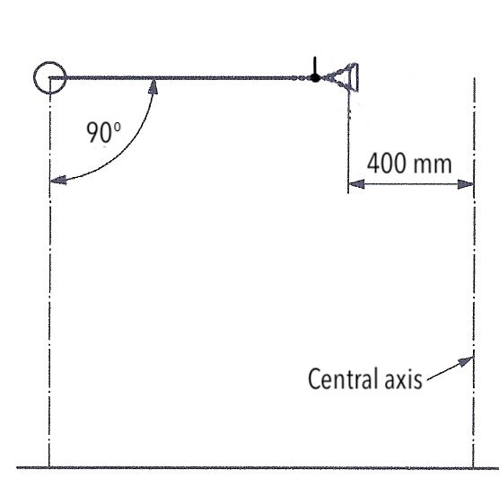
Swings
 FHoF is measured from the middle of the seat to the surface below
 when raised at 60o to the vertical.
                                                                                                                                                          60o
 This can simply be calculated using the following formula:
       Length of the suspension member (vertical height from seat to                                                                     h
       pivot point) ÷ 2 + height of swing seat at rest.

 Slides
 The FHoF of the slide corresponds to the actual seating
 surface of the slide at any given point.
 The surface around the run-out section of the slide shall
 have a critical fall height of at least 1000 mm.

  Carousels

  (a)     Standard Carousels – The impact area around carousels shall have a             (a)                                  (b)                                     (c)
          critical fall height of at least 1000 mm.
  (b)     Inclined Discs – The impact area shall have a critical fall height of at
          least 1000 mm.
  (c)     Bowl-like Carousels – The impact area shall have a critical fall height
          of at least 1000 mm.
  (d)     Spinning Poles (< 500mm diameter) – FHoF is measured as the
          platform height to the ground below but is always deemed at least          (d)                     (e)
          600mm.
  (e)     Overhead Carousels – FHoF is measured as the grip/seat height (if
          the grips are flexible, angled at 30o) minus 1500mm, but the critical
          fall height of the surface must be at least 1000mm.

Rocking Equipment

FHoF is measured from the centre of the seat in                                                      h
                                                            h
its most extreme position to the ground below.
The impact area shall have a critical fall height of                                                                                                                                h
at least 600mm, where the actual height is less
than 600mm.

 Flying Foxes

 FHoF is measured from the seat (unloaded) to the surface below or from the grip
 position (unloaded) minus 1.5 m to the surface below.
                                                                                                                                    Figure 4 — Principal measurement of effective dia
        Note: The minimum ground clearance below the seat when loaded with 68.5 kg
        is 350mm.                                                                                              4.3    Protection against injuries in the falling space

 The surface below a flying fox shall have a critical fall height of at least 1000 mm.                          The free height of fall (h) shall
                                                                                                                                             h    be as given in EN 1176-1:2008, 4.2.8.1
                                                                                                              h Figure 5.

                                                                                                               NOTE 1 For spatial network this means the highest foot position giving an unim
 Activity Nets (with a cellular network structure)
 FHoF is measured from the highest foot position giving an unimpeded fall to the
 surface below. (Falls from higher portions of the net will be broken by the net
 structure below when the net structure is within the falling space of such points.)

  Bouncing Facilities (Bouncing Mats)

  FHoF is measured from the suspension bed to the lowest                                                                                                        h

  point of the falling space plus 900mm.

  Note: Typically, bouncing facilities do not act as trampolines as
                                                                                                                                                             Figure 5 — Free height of fall
  they do not allow for high jumps or encourage acrobatic                                                h
                                                                                                     h

  jumps, which are more likely to lead to serious injuries.                                                    NOTE 2      Persons climbing on the outside of inclined 3-dimensional climbing
                                                                                                               outside, due to their orientation while climbing, but fall vertically downwards into

                                                                                                               When non-flexible elements (e.g. support poles) are arranged in a sla
                                                                                                               face, they have a deflecting character and the impact energy is reduce
                                                       Figure 2 – Specific means of determining FHoF
                                                                                                  can then be increased in accordance with Table 1.

                                    A Guide to the Australian Playground Standards (written by Andrew Reedy – Play Check)                                    Page 8 of 30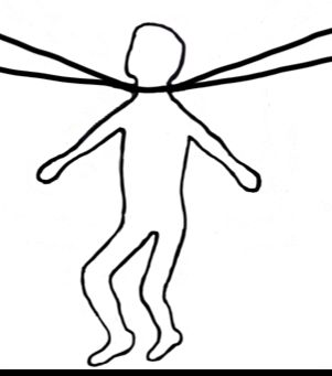
Table 2 – Maximum allowable free height of fall (FHoF) limits

                                     Type of use                          Measured from                                   Maximum allowable
Equipment type                                                                                                            FHoF
Equipment easily accessible to       Standing                             Foot support to surface below                   3m
all ages
                                     Sitting                              Seat to surface below                           3m

                                     Hanging                              Hand support to surface below                   3m

                                     Climbing (when access to the top     Highest climbable point to the surface          3m
                                     of the item is provided)             below
                                     Climbing (with sufficient distance   Maximum hand support minus 1m to the            3m
                                     to deter climbing to the top)        surface below                                   (max hand support 4m)
                                     Steep play elements                  Platform to the surface below                   2m

Equipment not easily accessible      Standing                             Foot support to surface below                   3m

                                     Sitting                              Seat to surface below                           3m

                                     Hanging                              Hand support to surface below                   3m

                                     Climbing (when access to the top     Highest climbable point to the surface          3m
                                     of the item is provided)             below
                                     Climbing (with sufficient distance   Maximum hand support minus 1m to the            3m
                                     to deter climbing to the top)        surface below                                   (max hand support 4m)
                                     Steep play elements                  Platform to the surface below                   3m

Supervised early childhood           Standing                             Foot support to surface below                   1.8m
services (SECS)
                                     Sitting                              Seat to surface below                           1.8m

                                     Hanging                              Hand support to surface below                   1.8m

                                     Climbing (when access to the top     Highest climbable point to the surface          1.8m
                                     of the item is provided)             below
                                     Climbing (with sufficient distance   Maximum hand support minus 1m to the            1.8m
                                     to deter climbing to the top)        surface below                                   (max hand support 2.8m)
Swings                               Sitting                              Middle of seat to surface below when            3.0m
                                                                          raised at 60° to vertical
Cableways                            Sitting                              Seat to surface below (unloaded)                2.0m

                                     Hanging                              Grip position minus 1.5m to surface             1.5m
                                                                          below (unloaded)
Carousels                            Standing / Sitting                   Foot support / seat to surface below            1.0m
(except overhead hanging types)

Carousels                            Hanging                              Grip position minus 1.5m or seat height         1.5m
(overhead hanging types)                                                  to surface below
Axial See-Saws                       Sitting                              Seat to surface below                           1.5m
                                                                          (at extreme positions)
Single Point See-Saw &               Sitting                              Seat to surface below                           1.0m
Rockers                                                                   (at extreme positions)
Multi Point See-Saw & Rockers        Sitting                              Seat to surface below                           1.0m
                                                                          (at extreme positions)
Rocking See-Saws                     Sitting                              Seat to surface below                           1.0m
                                                                          (at extreme positions)
Sweeping See-Saws (multi-            Sitting                              Seat to surface below                           2.0m
directional)                                                              (at extreme positions)
Overhead Single Axis See             Sitting                              Seat to surface below                           2.0m
Saws                                                                      (at extreme positions)
Spatial Networks                     Climbing                             Point from which there is no unimpeded          3.0m
                                                                          fall to surface below
Bouncing Facilities                  Bouncing                             From the suspension bed to the lowest           N/A
(Bouncing Mats)                                                           point of the falling space + 900mm

                                  A Guide to the Australian Playground Standards (written by Andrew Reedy – Play Check)                   Page 9 of 30
Surfacing requirements
The ‘critical fall height’ (CFH) of a surface is the maximum free height of fall for which a surface will provide an
acceptable level of impact attenuation. The required CFH for a surface will generally equal at least the free height
of fall of the equipment, but may be greater in the case of equipment causing a ‘forced movement’ of the body.
In these cases, the surface may have a CFH that exceeds the actual fall height of the equipment (as detailed in
Figure 2 in the previous section.
Note: Forced movement is defined as movement of the user caused by the equipment (e.g. swinging, sliding,
carousel rotation etc.) which, once started, cannot be totally controlled by the user.
When conducting on-site impact testing, the ‘measured fall height’ of the equipment (which is calculated as the
‘free height of fall’ plus an additional 10% allowance) can be used to reduce the number of drop-tests required.
Fall heights below 600 mm
There is no impact attenuating surface requirement for equipment with a ‘free height of fall’ of less than 600mm
unless forced movement exists (see below).
Fall heights above 600 mm and below 600 mm where forced movement exists
For equipment with a free height of fall above 600 mm, or where forced movement exists, the surfacing
requirements shall meet the requirements of AS 4422:2016 (Playground surfacing – specifications, requirements
and test method), for the respective heights.
The minimum ‘critical fall heights’ for various types of forced movement equipment where the actual equipment
height is less than the required ‘free height of fall’ are detailed in Figure 2. In instances where the actual ‘free
height of fall’ of a particular item of equipment exceeds these minimum critical fall heights for that type of
equipment, the critical fall height shall be at least that required for the actual ‘free height of fall’.
Note: Adjacent platforms are permitted to have a free height of fall of up to 1m without impact attenuation on
the lower platform. Above this height the surface of the lower platform shall present the necessary impact
attenuating properties.
Impact area, falling space and free space
The requirements for falling space, free space and the impact area around the playground equipment are
intended to offer some protection to users during the initial impact of a potential fall.
The ‘impact area’ (often referred to as fall-zone) deals with the surfaces that can be hit as a result of a fall. The
‘falling space’ and ‘free space’ are 3-dimensional spaces around the equipment. ‘Free space’ specifically relates to
the space around a user undergoing ‘forced movement’.
Specific requirements relating to the minimum space around playground equipment are detailed in the following
sections.
3
2 1. Impact area
2. Falling space
3. Free space
1
Figure 3 – Example of falling space
and impact area
A Guide to the Australian Playground Standards (written by Andrew Reedy – Play Check) Page 10 of 30Impact area (often referred to as ‘fall zone’)
The impact area is the area that can be hit by a user falling from the playground equipment. The general
dimensions of the impact area are shown in Figure 4 and Table 3.
Table 4 details specific requirements relating equipment where the extent of the impact area is increased as a
result of forced movement. The impact area may also be decreased in certain cases, such as when the equipment
is fully enclosed or installed on or against a wall.
Generally, the impact areas of different equipment may overlap, however in the case of equipment where forced
movement exists there are restrictions to overlapping, as detailed in Table 4 and under the following headings
‘falling space’ and ‘free space’.
Table 3 – Extent of the impact area (general requirements)
Extent of
FHoF Surfacing requirements
impact area
No forced movement < 0.6m ≤ 1500 mm * Surface with no requirements
See Table 4 for specific requirements
Forced movement < 0.6m
for items involving forced movement.
0.6m ≤ h ≤ 1.5m 1500 mm
1.6m 1567 mm
1.7m 1633 mm
1.8m 1700 mm
1.9m 1767 mm
2.0m 1833 mm
2.1m 1900 mm Impact attenuating surfacing
tested in accordance with
2.2m 1967 mm
AS 4422:2016
2.3m 2033 mm
2.4m 2100 mm
2.5m 2167 mm
2.6m 2233 mm
2.7m 2300 mm
2.8m 2367 mm
2.9m 2433 mm
3.0m 2500 mm
* Note: While the Standard shows non-moving equipment with a FHoF of less than 600 mm as having a impact area and indicates that this can be reduced below
1500 mm in some instances to allow for play elements such as stepping stones, the surface in this area has no impact attenuation requirement.
A Guide to the Australian Playground Standards (written by Andrew Reedy – Play Check) Page 11 of 30Table 4 – Extent of the impact area (specific requirements based on movement)
Equipment Type Extent of impact area Diagrams
Swings LENGTH
The minimum length of the impact area (L) is
equal to A + B or A + C, where:
A = the horizontal distance when the seat has
travelled through an arc of 60°, which can be
calculated as the length of the suspension
member (h) x 0.867.
B = 1750 mm, where the surface is level with the
surrounding surface (normally synthetic), or in all
cases in SECS settings. In this instance there 500
should be an additional area extending 500m that mm
is free from obstacles.
C = 2250 mm, where the surface is contained
(normally loose fill).
WIDTH
The minimum width of the impact area (W) below
each swing seat with a width of less than 500 mm
shall be 1750 mm. If the seat is wider than 500
mm the width of the impact area shall increase by
the difference between the actual width and 500
mm.
Note: The falling space and free space of
adjacent seats on the same frame may
overlap, provided correct spacing is achieved.
In the case of single point swings (which allow
movement through more than one axis or plane)
the extent of the impact area shall be circular with
a radius calculated above as L.
Note: The impact area of a swing cannot
overlap the impact area of another item of
equipment.
Slides TO THE SIDES
The impact area to the sides of the slide shall
correspond to the general FHoF requirements for
the height of the slide at various points where the
height of the sliding surface is 600 mm or above.
Where the sliding surface is below 600 mm the
impact area shall extend at least 1000 mm to the
sides of the run-out section.
FROM THE END 600 mm
high
The impact area beyond the run-out section is
dependent on the type of slide as follows:
Type 1: (most slides fall into this category)
Impact area to extend:
- 2000 mm beyond the run-out section if the
sliding section is greater than 1500 mm, or
- 1500 mm if the sliding section is less than A B C
1500 mm.
The last metre shall have a 1000 mm radius in
line with the outside edge of the slide. 2000 mm
or 1500 mm if sliding
section < 1500 mm
Type 2: (generally very long slides)
Impact area to extend 1000 mm beyond the run-
out section. This is applicable only where the A starting section
length of the run-out section of the slide is at B sliding section
least 0.3 x the length of the sliding section. C run-out section
R radius of impact area
Note: The free space around a slide (see
‘free space’ in the following section) cannot
overlap the impact area of another item of
equipment.
A Guide to the Australian Playground Standards (written by Andrew Reedy – Play Check) Page 12 of 30Equipment Type Extent of impact area Diagrams
Carousels SPINNING POLES (diameter < 500 mm) &
BOWL-LIKE CAROUSELS
The impact area shall extend at least 1500 mm
from the outside of the standing platform/bowl.
Note: Overlapping of the impact area of
spinning poles with a diameter of less than
500mm and single-user bowl-like carousels
with the impact area of other items of
equipment is permitted. These items are not
deemed to have free space. Bowl-like
carousels for more than one user are
considered to have free space, which
extends 1000mm from the perimeter and
cannot overlap the impact area of another
item of equipment.
STANDARD CAROUSELS, ROTATING NETS &
REVOLVING RINGS
The impact area shall extend at least 2000 mm
from the outside of the carousel.
Note: The impact area of these types of
carousel cannot overlap the impact area of
another item of equipment.
INCLINED DISC (on an inclined axis with no
clearly definable user stations)
The impact area shall extend at least 3000 mm
from the outside of the carousel.
Note: The impact area of this type of carousel
cannot overlap the impact area of another
item of equipment.
OVERHEAD CAROUSELS
The impact area shall extend at least 2000 mm
from the outside of the carousel.
In the case of carousels with flexible grips/seats,
the impact area is measured from the grips/seats
when they are angled out by 30°.
In addition, the area extending 1000 mm beyond
the impact area shall be free of obstacles.
Note: The impact area of these types of
carousel cannot overlap the impact area of
another item of equipment.
Rocking Equipment STANDARD ROCKING EQUIPMENT
The impact area shall extend at least 1000 mm
beyond the perimeter of the equipment when in
its most extreme position.
If the seat height exceeds 600 mm (such as in
the case of see saws), the extent of the impact
area shall be at least 1500 mm.
If the equipment is intended to be used in a
standing position the impact area shall be at least
1500 mm.
Note: Standard rocking equipment relying on
springs or other damping means are not
considered to have forced movement, so
overlapping of the impact area is permitted.
This does not apply to axial see saws.
A Guide to the Australian Playground Standards (written by Andrew Reedy – Play Check) Page 13 of 30Equipment Type Extent of impact area Diagrams
Rocking Equipment SWEEPING SEESAW (in which both vertical and
(cont’d)
horizontal movement takes place, which may
result in a sweeping motion.)
The general requirements for the extent of the
impact area apply based on the height of the user
stations when in their extreme position. The
general requirements then apply for that height
(see Table 3).
Note: The free space (see ‘free space’ on the
following page) cannot overlap the impact
area of another item of equipment.
OVERHEAD SINGLE AXIS SEESAW (with a
single overhead rocking axis, where the user
stations are flexibly suspended below and
provide and additional limited singing motion.)
The general requirements for the extent of the
impact area apply based on the height of the user
stations when angled at 20° from the vertical (see
Table 3).
Note: The free space (see ‘free space’ on the
following page) cannot overlap the impact
area of another item of equipment.
Cableways
TO THE SIDES
The impact area shall extend at least 2000 mm to
each side of the cableway.
FROM THE ENDS
The impact area shall extend at least 2000 mm
beyond the end of the handgrip or seat when
swinging at an angle of 45° from the compressed
end stop, with the width reducing to an overall
width of 2000 mm.
Note: The free space (see ‘free space’ on the
following page) cannot overlap the impact
area of another item of equipment.
Bouncing Facilities
The impact area of a small bouncing facility (with
(Bouncing Mats) a suspension bed of less than 1.44m2) shall
extend at least 1500 mm.
The impact area of a large bouncing facility (with
a suspension bed greater than 1.44m2) shall
extend at least 2000 mm.
Note: The free space (see ‘free space’ on the
following page) cannot overlap the impact
area of another item of equipment.
A Guide to the Australian Playground Standards (written by Andrew Reedy – Play Check) Page 14 of 30Falling space
Falling Space is the space in or around the Falling Space
equipment that can be passed through by a user
falling from an elevated part of the equipment.
The falling space is a 3-dimensional area,
commencing at the free height of fall and extending
over the same horizontal dimensions that apply to
the extent of the impact area (as indicated in
Figures 4 & 5 and Tables 2 & 3) then extending
vertically to the impact area below.
In most cases the falling spaces of different items of
equipment may overlap, except in the case of
equipment involving ‘forced movement’ where
overlapping should not occur.
The falling space shall not contain any obstacles
(e.g. hard or sharp objects or tree branches) that a
user could hit, causing injury, during a fall from an
elevated position. Examples of such hazards
include exposed foundations and posts not flush Figure 5 – Extent of the falling space
with adjacent parts.
The intention of this requirement is not to protect the user from minor
knocks or bumps, that might lead to a bruise or strain, etc., as these types of injuries are possible in all situations.
The following items are permitted within the falling space:
- Adjacent parts of play structures (or other items) with a difference in free height of fall of less than
600 mm;
- Parts of the equipment bearing or containing the user, or helping the user maintain balance (e.g. a
platform adjacent to a fireman’s pole, or a rung below a monkey bar);
- Parts of the equipment with an inclination of 60o or more from the horizontal. (In this case a falling user
would only make a glancing contact with the equipment part.)
Free space
Free space is the space immediately around a user undergoing forced movement. Forced movement is defined as
movement of the user caused by the equipment (e.g. swinging, sliding, carousel rotation, bouncing etc.) which,
once started, cannot be totally controlled by the user. It applies to slides, fireman’s poles, cableways (flying
foxes), swings, carousels, spring rockers and bouncing facilities.
Free space is represented as a series of cylindrical spaces (see Figures 6 & 7) originating from and perpendicular
to the surface bearing the user and along the path of movement. It does not include the three-dimensional area
in which the falling movement takes place.
There shall be no overlapping of adjacent free spaces, or of free space and falling space. This requirement does
not apply to the common space between pieces of equipment in a cluster (a cluster is defined as two or more
pieces of equipment designed to be installed in close proximity to each other to provide continuity in a sequence
that is needed for the play activity). The free space of multi-track slides may also overlap.
Parts of the equipment bearing or containing the user, or helping the user to keep balance (e.g. a platform
providing access to a fireman’s pole, and the supporting posts on a spiral slide) are permitted within the free
space.
A Guide to the Australian Playground Standards (written by Andrew Reedy – Play Check) Page 15 of 30The free space of an item shall not contain any obstacles (e.g. other items of equipment or tree branches) that
interfere with the passage of or are in the path of the user whilst undergoing forced movement, nor should it be
intersected by main travelling routes through the playground, such as a pathway. Consideration should be given
Determination of the free space; example of a slide
to the placement of surrounding items that may encourage a child to intersect the free space by running from
one activity to another via the most direct route.
Dimensions in millimetres
Radius
Height
Figure 7 – Example of free space
Figure 6 – Cylindrical space on a slide
representing free space
er b) Standing user
Figure 16 — Cylindrical space Table 5 – Dimensions of the cylinder for the determination of free space
Type of use Radius Height
Standing 1000 mm 1800 mm
Sitting 1000 mm 1500 mm
300 mm above and 1800 mm below the
Hanging 500 mm
hanging grip position
Carousels
2000 mm to the side of the carousel and
(additional requirements due to At least 2000 mm above the carousel
3000 mm in the case of giant revolving disks
centrifugal force.)
Protection against falling
When determining the level of protection against falling required for various items of playground equipment it is
necessary to ascertain the intended type of use of the equipment (see ‘categories of playground equipment’ on
page 6). The level of protection required will vary between equipment that is easily accessible to all ages and
equipment deemed not easily accessible.
Types of protection
Protection against falling can be provided in the form of handrails, guardrails and barriers. Figures 8 & 9 and
Table 6 provide detail of the requirements for protection for each category of equipment at various heights.
Handrails
A handrail is defined as a rail intended to assist the user to keep balance. The height requirement for handrails is
set out in Table 6. The use of more than one handrail is permissible provided they do not create any openings
that may result in entrapment (as defined under “Protection against entrapment”). The cross section of any
handrail must not exceed 60 mm in width (grasp).
A Guide to the Australian Playground Standards (written by Andrew Reedy – Play Check) Page 16 of 30Handrails/guardrails may be used on stairs and ramps leading to platforms up to 1m in height. Above this height
barriers are required. Climbing items at heights above 1m are still permitted to have handrails. When installed
on ramps or stairs, handrails, guardrails or barriers shall commence at the lowest position on the ramp or stairs.
Guardrails
A guardrail is defined as a rail intended to prevent the user from falling from the equipment. When used on a
platform, guardrails shall be at a height of between 600 mm and 850 mm above the standing surface and shall
completely surround the platform, except for entry and exit openings necessary for other items of play
equipment. The width of these entry or exit points shall have a maximum clear opening of 500 mm, except in the
case of stairs, ramps and bridges, where the width of the opening shall be no greater than the width of the
adjoining element.
Slides greater than 1000 mm in height require a guardrail above the starting section of the slide, positioned
between 600 mm and 900 mm above the slide surface (towards the upper end of this limit is generally more
functional).
Note: Where guardrails are specified this is a minimum requirement and does not preclude the use of barriers.
Barriers
A barrier is defined as a device intended to prevent the user from falling from the equipment and from passing
beneath. Barriers are used on platforms, stairs, ramps or rigid bridges.
The construction of the barrier should be such that there are no horizontal or near horizontal rails or bars or any
infilling, that can be used as steps by children attempting to climb. The design of the top of the barrier should not
encourage children to stand or sit on them. Openings in the barriers should not create any form of entrapment.
On equipment that is ‘easily accessible’ to younger children, any platform (defined as a surface where users can
stand without the need of hand support) above 600 mm in height should have a barrier at least 700 mm high to
prevent falls. (While 700 mm is the minimum according to the Standard, barriers are typically higher than this in
practice.)
Figure 8 – Protection against falling
A Guide to the Australian Playground Standards (written by Andrew Reedy – Play Check) Page 17 of 30Openings in barriers
Clear openings in the barriers at access/egress points should not be greater than 500 mm in width unless a
guardrail spans the top of the opening, in which case the opening may be wider (see figure 9).
- In the case of equipment deemed ‘easily accessible’, ‘steep play elements’ cannot have an opening
exceeding 500 mm in width, even with a guardrail.
- For equipment deemed ‘not easily accessible’, the opening above ‘steep play elements’ can be a
maximum of 1200 mm provided a guardrail is placed above the opening.
Steep play elements leading to platforms with a fall height greater than 1000 mm shall have hand
supports/handgrips to aid in transition onto the platform (see figure 10).
Figure 9 – Entry/exit openings in Barriers
Figure 10 – Examples of hand support/grip for steep play elements
A Guide to the Australian Playground Standards (written by Andrew Reedy – Play Check) Page 18 of 30Grip & Grasp
Items intended for grip (when support of full body weight is required)
shall have a cross-section of between 16 mm and 45 mm when measured
in any direction.
Items intended for grasp shall have a cross-section with a maximum
width of 60 mm. Grip Grasp
Figure 11 – Grip & Grasp
Table 6 – Requirements for Protection
Type of Impact Attenuating
Setting Equipment Height (h) Minimum Protection Requirements
equipment Surfacing
Equipment easily Platforms
accessible to all h < 600 mm No barriers or guardrails required. Not required
ages
Barrier (minimum height above standing surface
700 mm).
600 mm ≤ h ≤ 3000 mm Maximum openings of 500 mm without a guardrail.
(Steep play elements Steep play elements have a maximum opening of
Required
have a maximum height 500 mm, even with a guardrail. For elements that
of 2000 mm) are not steep the opening can be as wide as the
element with a guardrail across the opening.
Stairs, Ramps
& Rigid Bridges Handrail(s) / guardrail(s) between 600 mm and
h ≤ 1000 mm Required
900 mm above standing surface.
1000 mm < h ≤ 3000 Barrier (minimum height above standing surface
Required
mm 700 mm).
Equipment not Platforms
easily accessible h < 600 mm No barriers or guardrails required. Not required
600 mm ≤ h < 1000 mm No barriers or guardrails required. Required
1000 mm ≤ h < 2000 Guardrail (between 650 mm and 850 mm above
Required
mm standing surface).
Barrier (minimum height above standing surface
700mm).
Maximum openings of 500 mm without a guardrail.
2000 mm ≤ h ≤ 3000 Steep play elements have a maximum opening of
Required
mm 1200 mm with a guardrail. For elements that are
not steep the opening can be as wide as the
element with a guardrail across the opening.
Supervised early Platforms
childhood h < 600 mm No barriers or guardrails required. Not required
services (SECS)
Barrier (minimum height above standing surface
700 mm).
Maximum openings of 500mm without a guardrail.
Steep play elements have a maximum opening of
600 mm ≤ h ≤ 1800 mm Required
500 mm, even with a guardrail. For elements that
are not steep the opening can be as wide as the
element with a guardrail across the opening.
Stairs, Ramps When only a single handrail is used – between
& Rigid Bridges 450 mm and 700 mm above standing surface.
h ≤ 1000 mm When 2 handrails are used – between 450mm and Required
900mm above stranding surface.
1000 mm < h ≤ 1800 Barrier (minimum height above standing surface
Required
mm 700 mm).
A Guide to the Australian Playground Standards (written by Andrew Reedy – Play Check) Page 19 of 30Protection against entrapment
Entrapment is defined as a hazard presented by the situation in which a body, or part of a body, or the clothing
can become trapped. The standard only considers certain types of entrapment where the user is not able to free
him/herself and injury is caused by the entrapment.
The various types of entrapment and their testing procedures are detailed in the following pages.
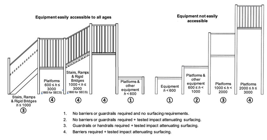
Head & neck entrapment – completely bound openings
These are openings though which a user can slide or squeeze, usually feet
first, or insert their head; and which will not allow the passage of the head
in its most unfavorable position (see Figure 12).
Bound openings, either vertical or horizontal, (e.g. in barriers, flexible nets,
log climbing frames, etc.) need to meet the following size requirements. If
the lower edge of the opening is greater than 600 mm above ground level,
any openings that allow the passage of the small torso probe (89 mm x 157
mm) or the small head probe (130 mm diameter), but do not allow passage
of the large head probe (230 mm in diameter) are unacceptable. In brief,
avoid any bound openings between 89 mm and 230 mm in any one
Figure 12 – Example of a bound opening that may
direction. cause head or neck entrapment
Test procedure
Apply each of the probes illustrated in Figure 13, with the axis of the probe perpendicular to the plane of the
opening.
If the probes are not freely passing through the opening apply a force of 222(±5)N to the probe.
NOTE: The large head probe dimensions are based on those for an older child and, therefore, there will be a
large tolerance if assessing for use by a young child.
Any openings that allow the passage of the Torso Probe or the Small Head Probe, but do not allow the passage of
the Large Head Probe fail the test and are unacceptable.
Figure 13 – Probes for determination of head and neck entrapment in completely bound openings
A Guide to the Australian Playground Standards (written by Andrew Reedy – Play Check) Page 20 of 30Head & neck entrapment – partially bound and V-shaped openings
These are openings into which a user can insert their neck and will
potentially prevent the head from easily rotating out, causing
strangulation.
Partially bound openings (e.g. gaps between the tops of adjacent
vertical boards on barriers) that are more than 600 mm above the
ground and greater than 45 mm in depth should comply with one of
the following:
- the width of the opening should be less than 45 mm (to
Figure 14 – Examples of partially bound or V-shaped
prevent possible insertion of the neck), or openings which may cause head or neck entrapment
- the width of the opening should be greater than 155 mm if
the depth of the opening is less than 265 mm on both sides, or
- the width of the opening should be greater than 230 mm if the depth of the opening is greater than 265 mm.
Note: Figure 15 provides partially bound opening requirements. Figure 20 provides some examples of
acceptable partially bound openings.
V-shaped openings that converge in a downward direction and are greater than 600 mm above the ground should
not be of an angle less than 60o, unless the depth of the opening is less than 45 mm.
Figure 15 – Examples of partially bound opening requirements
Test procedure
Firstly, determine whether an opening is deemed to be accessible or
not by applying the ‘B’ portion of the probe (representing the neck)
between and perpendicular to the boundaries of the opening. If the
probe can be inserted to its full thickness (45 mm) it is deemed to be
accessible and further testing is required to determine whether it
poses a hazard. If the probe cannot be inserted to its full thickness
the opening is deemed not accessible and no further testing is
required. (See Figure 17.)
Figure 16 – Probe for assessment of head and neck
entrapment in partially bound and V-shaped openings
A Guide to the Australian Playground Standards (written by Andrew Reedy – Play Check) Page 21 of 30Accessible Not accessible
Figure 17 – Method for determining the accessibility of a partially bound or V-shaped opening
If the opening is accessible, test further using portions ‘A’ and ‘B1’ of the probe (representing the head and
shoulders).
The testing procedure for accessible openings varies slightly depending on the angle of the opening. To
determine the testing range of the opening, insert the ‘A’ portion of the probe into the opening. The angle of its
centre line determines the range (see Figure 18). Testing procedures for both ranges are shown in Figure 19.
Centreline Centreline
of probe of probe
Figure 18 – Determining angle range for partially bound openings
Range 1 (45o – 90o) Range 2 (0o – 45o)
Pass Fail
Pass Fail
Figure 19 –Test method for partially bound and V-shaped openings
< 230
< 45 < 45 < 155
> 265
> 45 > 45 > 45 > 45
< 45 < 265
80 80 80 80 80 80 80 80 80 80 80 80
40 40 80 80
Figure 20 – Examples of acceptable partially bound opening configurations
A Guide to the Australian Playground Standards (written by Andrew Reedy – Play Check) Page 22 of 30Head & neck entrapment - non-rigid or flexible openings
Non-rigid members, such as ropes or chains, may create a hazard if they can overlap and if,
by doing so, they create openings that do not conform to the requirements for completely
bound openings. (This may involve adjacent flexible items, or a flexible and a rigid item, such
as a chain or rope on a climbing ramp).
Openings between flexible parts of suspended bridges and any rigid side members
shall not be less than 230 mm in diameter under the worst case of loading. Such Figure 21 – Example of flexible
openings should be tested both loaded and unloaded. members creating entrapment
Clothing entrapment
Hazardous situations where items of clothing can be caught while the user
is undergoing forced movement (e.g. sliding) should be avoided.
Possible situations in which clothing entrapment can be encountered are
as follows:
a) Gaps or V-shaped openings in which a part of clothing can become
trapped while or immediately before the user is undergoing forced
movement (e.g. sliding);
b) Protrusions (e.g. sharp edges on which clothing could be caught);
and
c) Spindles/rotating parts (such items should be free of any
protrusions that could catch on clothing while in use).
Figure 22 – Examples of situations which
may create clothing entrapment hazards
Test procedure (gaps & V-shaped openings)
Gaps and V-shaped openings in the free space are tested using the toggle test device (see Figure 23).
This test is applied to the free space of slides, fireman’s
poles and roofs (which may provide a hazard if a user were
to access and slide off whilst an item of clothing was
trapped).
SLIDES
Position the test device perpendicularly in the starting
section of the slide, 200 mm from the transition point of KEY
1 Pole
the starting section, and in the centre of a narrow slide or 2 Chain – 3.6 (±0.1) mm diameter
200 mm from the edge of a wide slide (see Figure 24). 3
4
Toggle – 25 (±0.5) mm diameter
Collar
Moving the test device in the direction of forced
Figure 23 –
movement, randomly place the toggle and chain under the Test device – toggle test
action of its own weight to all positions within the range, without applying
additional force or influence (this is to replicate the
natural motion of a clothing toggle).
In the event that the test device is obstructed, apply a
maximum force of 50N in the direction of the forced
movement. If the toggle is released this position within
the equipment passes the test.
Figure 24 – Position of test device on slides
A Guide to the Australian Playground Standards (written by Andrew Reedy – Play Check) Page 23 of 30FIREMAN’S POLES
Conduct the test using the testing device in two different positions:
(i) Position the complete device vertically at the edge of the platform at the point closest to the
fireman’s pole.
(ii) Detach the toggle, chain and collar from the device and
position it so that it is at a point 1.8m above the surface of
the adjacent platform, or the highest point on the pole if it
extends less than 1.8m (see Figure 25).
Randomly place the toggle and chain under the action of its own weight
to all positions within the range, without applying additional force or
influence. Apply this test down the length of the fireman’s pole to a
point 1.2m above ground level.
In the event that the test device is obstructed, apply a maximum force of
50N in the direction of the forced movement. If the toggle is released
this position within the equipment passes the test.
ROOFS
Figure 25 – Position of test device on
Detach the toggle, chain and collar from the device. Randomly place the fireman’s poles
toggle and chain under the action of its own weight to all positions at the
apex or along the surface of the roof, without applying additional force or influence.
If the toggle or the chain resists removal, apply a maximum force of 50N in the direction of any potential sliding
movement of the user. If the toggle is released this position within the equipment passes the test.
Entrapment of the whole body
Equipment shall be constructed in such a way that the following situations, which may cause entrapment of the
whole body, are not created:
a) Tunnels into which children can crawl with their whole
body (see requirements in Table 7).
Table 7 – Requirements for tunnels Figure 26 – Tunnels
Open one end Open both ends
≤ 5° (upwards ˃ 15° (should include
Inclination ≤ 15°
from entry only) steps or handles)
Maximum length ≤ 2000 mm ≤ 1000 mm ≤ 2000 mm NONE NONE
Minimum internal dimension
≥ 750 mm ≥ 400 mm ≥ 500 mm ≥ 750 mm ≥ 750 mm
(at narrowest point)
b) Suspended parts which are heavy or have rigid suspension
(where the dimension of the gap changes during use, creating a
potential crush point). Heavy suspended beams (weighing more
than 25kg) should have a ground clearance of at least 400 mm.
Figure 27 – Suspended parts
A Guide to the Australian Playground Standards (written by Andrew Reedy – Play Check) Page 24 of 30You can also read