SEISMIC ENGINEERING - ATENA SPA

Page created by Alfred Frank
 
CONTINUE READING
SEISMIC ENGINEERING - ATENA SPA
FALSE CEILINGS

SEISMIC
ENGINEERING

     FA L S E C E I L I N G S A N D C O V E R I N G S
SEISMIC ENGINEERING - ATENA SPA
FA L S E C E I L I N G S A N D C O V E R I N G S

                INNOVATIVE ARCHITECTURAL SOLUTIONS                                                                                          For over 30 years Atena has been designing and manufacturing false
                                                                                                                                            ceilings, external claddings and high quality naval fittings, producing in its
                         HIGH PERFORMANCE SYSTEMS                                                                                           factory in Italy and distributing in over fifty countries, through its dealers

                   ORIGINAL EXPRESSIVE POSSIBILITIES                                                                                        and partners.

                                                                                                                                            Without any limit to its technical development, Atena offers innovative
                                                                                                                                            solutions to realize the concepts of designers from all over the world.
                                                                                                                                            It stands out for its ability to execute the most challenging projects by
                                                                                                                                            creating special metal products for interiors and facade architecture.

                                                                                                                                            To the commercial synergy with different international realities, Atena
                                                                                                                                            combines direct collaboration with designers and companies, being able to
                                                                                                                                            give its customer a 360 degrees assistance, from concept to installation;
                                                                                                                                            providing a qualified executive design service and specialized consultancies
                                                                                                                                            in acoustics, lighting and seismic engineering.

2                                                                                                                                                                                                                            3
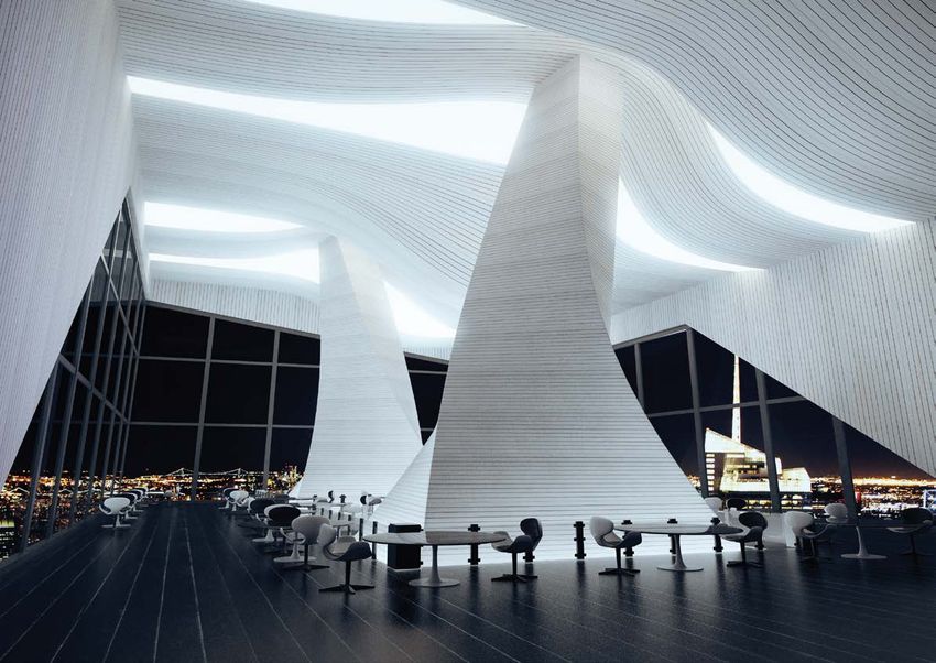
    Photo: “Atena Monolithic Islands System”, new Danieli Autyomation S.p.A. offices, Mingotti Architetti associati studio. Buttrio (UD).
SEISMIC ENGINEERING - ATENA SPA
Anti-seismic techniques are the only ones capable of effectively ensuring a
                                                                       preventive protection from material damages and of people safety.
                                                                       In this context, the regulatory framework has made the design criteria of
                                                                       structural, primary, secondary and nonstructural elements increasingly
                                                                       stringent. Among these nonstructural elements, the false ceiling plays a
                                                                       leading role, because its possible - even partial- fall can bring to serious
                                                                       safety risks and deadly consequences.

                                                                       In this area, Atena has been involved for over ten years with constant
         TECHNICAL AND FUNCTIONAL ASPECTS                              theoretical and experimental research. This led to the realization of

    AESTETHIC VALUE AND EXECUTIVE PRECISION                            patented systems for anti-seismic ceilings, capable of effectively dissipating
                                                                       telluric energy, preventing the elements from falling.
                     CUSTOMIZED SOLUTIONS
                                                                       The experimental campaign conducted with University of Padova’s
                                                                       Department of Civil, Construction and Environmental Engineering (DICEA),
                                                                       allowed to test the performance of the Atena Antiseismic Line with
                                                                       a last generation experimental apparatus. The results obtained have
                                                                       demonstrated the effectiveness of the systems adopted and became the
                                                                       starting point of the new models of anti-seismic kits for great heights.

                                                                       Designing can be simple; the Atena Antiseismic Line includes technical
                                                                       solutions and punctual advice for sizing the false ceiling system: together
                                                                       we can overcome construction site constraints and give shape to new
                                                                       design standards.

4                                                                                                                                                       5
    Photo: “Atena 15 Linear Design System”, Amazon Offices. Romania.
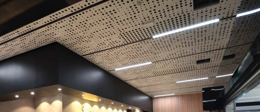
SEISMIC ENGINEERING - ATENA SPA
INDEX
                                                           8    SEISMIC ENGINEERING

                                                           9    SEISMIC RISK

                                                           12   REGULATORY FRAMEWORK

                                                           12   DESIGN CRITERIA

                                                           14   LIMIT STATES

                                                           20   ATENA EXPERIMENTAL CAMPAIGN

                                                           28   ANTI-SEISMIC SYSTEMS Plenum ≤1,2 m
    ATENA-IT.COM                                           40   ANTI-SEISMIC SYSTEMS Plenum >1,2 m
6                                                          52   FREQUENTLY ASKED QUESTIONS
                   Photo: Atena 24 Linear Tegular System
SEISMIC ENGINEERING - ATENA SPA
ANTI-SEISMIC ATENA LINE

    SEISMIC ENGINEERING                          SEISMIC RISK

    Seismic engineering studies the
    mechanical response of structures
                                                     SEISMIC HAZARD
    to earthquakes, the methodologies                MAP
    for designing of new buildings and
    for adaptation of existing buildings,
    according to anti-seismic criteria to            The seismic hazard map of the national territory introduced with the Ministerial
    reduce the seismic risk.                         Decree 14.09.2005 provides a picture of the most dangerous areas in Italy in terms
                                                     of horizontal acceleration of the soil with a probability of excess of 10% in 50
    Anti-seismic techniques are the only             years, referred to rigid soils (V s30> 800 m/s; cat. A, point 3.2.1 of Ministerial Decree
    ones capable of effectively ensuring             14.09.2005). The subsequent PCM ordinance n.3519/2006 has made the map an
    a preventive protection from material            official reference tool for seismic design, and has introduced a new calculation
    damages and of people safety.                    system based on a point-distributed statistical approach, which allows to precisely
    In this sense, the structural dynamics           define the seismic hazard of a site.
    plays an important role both in the design
    from scratch, and in the interventions           For each construction it is therefore necessary to consider a specific reference
    of existing structures reinforcement, so         seismic acceleration value, identified on the basis of the geographical coordinates
    that they can withstand severe dynamic           of the project area, depending on the nominal life of the work.
    actions, due for example to earthquakes,
    hurricanes, wind, etc.                           When the Technical Standards for Construction, NTC, (Ministerial Decree 14.01.2008
                                                     updated with Ministerial Decree 17.01.2018) entered into force, the anti-seismic
                                                     design criteria have also been extended to non-structural construction elements,
    The fundamental criterion of conventional
                                                     such as false ceilings, which must be verified together with the connections
    anti-seismic constructions is that of
                                                     to the structure.
    realizing works that allow saving human
    lives, while sacrificing the structural
    integrity of buildings.
                                                                                                    85% of Italian national surface is characterized by a
                                                                                                       significant seismic risk. In these areas 80% of the
    The latest generation of seismic isolation                                                                Italian population resides, occupying insecure
    techniques allow structures design                                                                          and obsolete buildings, built in most cases
    that are not subject to soil vibrations,                                                                       before the introduction of anti-seismic
    by applying seismic isolators. Placed                                                                             regulations. The interventions to reduce
    between the foundations and the                                                                                      the buildings vulnerability are inserted
    superstructure, they reduce the transfer                                                                                in this context, in order to reduce
    of stress from the ground                                                                                                 the seismic risk of the overall
    to the superstructure itself.                                                                                                Country System.
    The isolation system therefore limits
    the intensity of the seismic action and
    consequently the transmission of the
    movements induced by it.
                                                                                                                                    Expected acceleration
                                                                                                                                    with a probability of 10%
    Increasing the time period of vibration of                                                                                      in 50 years (g).
    the building, through a suitable isolation
                                                                                                                                               0 - 0.25 g
    system, is one solution to obtain the                                                                                                      0.025 - 0.05
    seismic force cutting at the base of the
                                                                                                                                               0.05 - 0.075
    structure. This allows the structure to                                                                                                    0.075 - 0.1
    get in the range of lower accelerations,                                                                                                   0.1 - 0.125
    which is a winning point of isolated                                                                                                       0.125 - 0.15

    constructions, compared with traditional                                                                                                   0.15 - 0.175
    ones. By decoupling the motion of the                                                                                                      0.175 - 0.2
                                                                                                                                               0.2 - 0.225
    ground from the motion of the building                                                                                                     0.225 - 0.25
    in this way, the structure remains intact
                                                                                                                                               0.25 - 0.275
    within the elastic field.                                                                                                                  0.275 - 0.3
8                                                     zonesismiche.mi.ingv.it - GdL MPS, 2004;                                                                      9
                                                      ref. PCM Ordinance of 28 april 2006, n. 3519, All. 1b
SEISMIC ENGINEERING - ATENA SPA
ANTI-SEISMIC ATENA LINE

     SEISMIC RISK                                                                      HAZARD, VULNERABILITY, EXPOSURE

     The seismic risk is the measure                                                Specifically, the seismic vulnerability of a
                                                                                    structure is represented by an indicator that                                       Figure A
     used in seismic engineering to
     assess the expected damage                                                     relates the capacity of resistance and / or
                                                                                                                                          HAZARD
     following a possible seismic                                                   displacement of the structure and the request
     event, and is a function of three                                              in terms of resistance and / or displacement
     variables:                                                                     of the earthquake. In this sense it is defined
                                                                                    as “the relationship between the seismic          VULNERABILITY
                                                                                    action corresponding to the achievement of                                          Hazard=10
     Risk R = H x V x E                                                             the capacity of the structure and the seismic
                                                                                                                                        EXPOSURE
                                                                                                                                                                   Vulnerability=10
                                                                                    demand at the ultimate limit state”.                                              Exposure=10
                                                                                                                                                                               Risk
                                                                                    Indicator extimation, according to the design                                   (HxVxE)=1000
                                                                                    procedure foreseen by paragraph 8.5 of the
     Hazard meant as the probability
                                                                                    NTC, is based on analysis, calculations, tests
     that a certain shaking value will
                                                                                    and linear and non-linear calculation methods.
     occur in a given time interval.
     Once some input elements                                                       Reducing the vulnerability index of the                                             Figure B
     and reference parameters are                                                   structure means intervening in terms of
     known (such as source zones,                                                   structural and non-structural adaptation of        HAZARD
     acceleration or displacement                                                   the building. Using a suitable false ceilings,
     shaking, type of soil) it is possible                                          for example, allows to lower the vulnerability
     to define the seismic hazard.                                                  index (Fig C), while the application of seismic
     The more likely it will be to have                                             insulators located between the foundations                     VULNERABILITY
                                                                   VU

                                                                                                                                                                         Hazard=10
     a seismic acceleration of a given                                              and the superstructure allows to reduce the
                                                   RD

                                                                     LN

                                                                                                                                                                   Vulnerability=10
     value within a certain time frame,                                             intensity of the seismic action, reducing both
                                                                       ER

                                                                                                                                                       EXPOSURE
                                                 ZA

                                                                                                                                                                        Exposure=1
     the higher the seismic hazard                                                  the vulnerability index and the exposure
                                                                         AB
                                               HA

                                                                                                                                                                               Risk
     will be.                                                                       factor (fig. B).
                                                                           ILIT

                                                                                                                                                                      (HxVxE)=100
                                                                                Y

     Vulnerability in meant as a                                                    In the images here aside, four different
     measure of the buildings’ ability                                              conditions are shown, where for the same
     to withstand the earthquake,                       EXPOSURE                    hazard in a given geographical area, the                                            Figure C
     as it indicates the possibility                                                seismic risk changes with exposure and
     that an area suffers in terms of                                               vulnerability. Let’s think for example of a           HAZARD
     economical damage, of lifes loss,                                              school building:
     or cultural heritage damages.                                                                                                    PROTECTION
     It should be remembered                                                        figure A describes a condition of maximum         SYSTEM
     that the earthquake is a non-                                                  Hazard: there are people in the building, even
                                             The seismic risk depends on                                                              VULNERABILITY                    Hazard=10
     periodic natural dynamic load,                                                 if it is not suitable in relation to the degree
                                             the interaction of 3 factors:          of physical hazard of the area in which it is                                  Vulnerability=5
     as its intensity, direction and / or                                                                                               EXPOSURE
                                                                                    located;                                                                         Exposure=10
     position varies over time. In this
                                               Hazard (H)                                                                                                                     Risk
     sense, one of the most important                                               In figure B the exposure is reduced preventing
                                               Vulnerability (V)                                                                                                    (HxVxE)=500
     applications of the theory of                                                  access to the structure but thus compromising
                                               Exposure (E)
     structural dynamics is surely                                                  its use;
     that of analyzing the response of
                                             To reduce the seismic risk it          In figure C the risk is reduced due to a
     structures to earthquakes.
                                             is necessary to intervene on           decrease in vulnerability only through                                              Figure D
                                             the factors that determine it.         interventions on structural, secondary and
     Exposure is intended as socio-          Not being able to intervene                                                                  HAZARD
                                                                                    non-structural components of the vulnerable
     economic evaluation of the              on the Hazard, which is                buildings;
     consequences of an earthquake,          the probability that the
     in relation to population density,      earthquake will occur, it              In figure D, the ideal situation, the
     quantity and value of historical,       will be necessary to work              interventions of design from scratch or           VULNERABILITY
     artistic and monumental heritage                                                                                                                                   Hazard=10
                                             in order to reduce Exposure            restructuring are radical and therefore a
     of a given place.                                                              twofold action occurs which affects both the                                   Vulnerability=5
                                             and Vulnerability.                                                                         EXPOSURE
                                                                                    vulnerability and the exposure.                                                    Exposure=1
10                                                                                                                                                                            Risk    11
                                                                                                                                                                      (HxVxE)=50
SEISMIC ENGINEERING - ATENA SPA
ANTI-SEISMIC ATENA LINE

                                                                                               NON-STRUCTURAL                                        SEISMIC
                                                                                               BUILDING ELEMENTS                                     DEMAND

                                                                                               As non-structural constructive              The seismic demand on non-structural
                                                                                               elements, we mean those with                elements can be determined by
                                                                                               stiffness, strength and mass such as
                                                                                                                                           applying a horizontal force Fa defined
                                                                                               to significantly influence the structural
                                                                                                                                           as follows:
                                                                                               response and those which are equally
                                                                                               significant for the purposes of safety
                                                                                               and / or the safety of people, while not
                                                                                               affecting the structural response.          Fa = (S a · Wa )/q a                 [7.2.1]

                                                                                               The capacity of non-structural
                                                                                               elements, including any structural          where
                                                                                               elements that support and link them,
                                                                                               must be greater than the seismic
                                                                                                                                           F a is the horizontal seismic force
                                                                                               demand corresponding to each
                                                                                               of the limit states to be considered        distributed or acting in the center of
                                                                                               (see § 7.3.6).                              mass of the non-structural element,
                                                                                                                                           in the most unfavorable direction,
                                                                                               When the non-structural element             resultant of the distributed forces
                                                                                               is built on site, it is the structure       proportional to mass;
                                                                                               designer’s responsability to identify
     REGULATORY FRAMEWORK                      7.2.3. DESIGN CRITERIA                          the demand and design its capacity          S a it is the maximum acceleration,
                                                                                               according to proper formulations and it     adimensionalized with respect to
                                               OF SECONDARY STRUCTURAL ELEMENTS
                                                                                               is a task of the construction manager       gravity, that the non-structural element
                                               AND NON-STRUCTURAL BUILDING
     The first anti-seismic regulation in                                                      to verify its correct execution. When,      undergoes during the earthquake and
                                               ELEMENTS                                        on the other hand, the non-structural
     Europe was born in the Kingdom of                                                                                                     corresponds to the analyzed limit state
     Naples, by the will of the Bourbons,                                                      element is assembled on site, tasks
                                                                                                                                           (see § 3.2.1);
     after the devastating earthquake that     Some structural elements can be considered      are divided as follows: the structure
     struck Calabria in 1783, but only with    “secondary”; in the analysis of the seismic     designer has to identify the demand,        W a is the weight of the element;
     the law of February, 2nd, 1974, n.64,     response, the stiffness and resistance to the   the supplier and / or installer has
     containing provisions for buildings       horizontal actions of these elements can be     to provide elements and connection          q a is the behavior factor of the
     with special requirements for seismic     overlooked.                                     systems with adequate capacity and          element.
     zones, the anti-seismic criteria are      These elements are designed to withstand        the construction manager has to check
     spread in the structural design           vertical loads only and to follow the           correct assembly.
                                                                                                                                           In the absence of specific determinations,
     practices of buildings.                   movements of the structure without losing
                                                                                                                                           for S a and q a, we can refer to documents of
                                               their bearing capacity.                         If the distribution of non-structural
     These aspects have been made more                                                                                                     proven validity.
     stringent after the tragic events of      The secondary elements and their                elements is highly irregular in plan,
                                                                                               the effects of this irregularity must be    The explanatory memorandum of the NTC
     2007 in Peru and 2008 in Italy.           connections must therefore be designed
                                                                                               evaluated and taken into account.           2018 n.7 of the C.S.LL.PP. of 01/21/2019
                                               and equipped with construction details
     Therefore specific anti-seismic                                                           This requirement is considered              reports the method of calculating the
                                               to support the gravitational loads, when
     design criteria also for plants and for   subjected to displacements caused by the        satisfied if the accidental eccentricity    adimensionalized acceleration (S a) and
     non-structural elements (par. 7.2.3)      most unfavorable of the ULS design seismic      referred to in § 7.2.6 is increased by a    establishes the factor q a equal to 2. Among
     have been introduced only with the        conditions, evaluated, in the case of linear    factor of 2.
                                                                                                                                           the international normative references we
     entry into force of the Technical         analysis, according to § 7.3. 3.3, or,          If the distribution of non-structural       cite as examples the Manuals for the visual
     Regulations for Constructions (NTC        in the case of non-linear analysis,             elements is strongly irregular
                                                                                                                                           survey of potential risk situations of the
     - 14/01/2008), replaced now by the        according to § 7.3.4.                           in height, we must consider the
                                                                                                                                           Federal Emergency Management Agency
     2018 update (D.M. dated 17,01,2018                                                        possibility of strong concentrations
     entered in force on 22.03.18) and the                                                     of damage at levels characterized by        (FEMA 154, FEMA 155, FEMA 178) of the
                                               In any case the choice of the elements
     publication of the guide lines for the    to be considered secondary structure may        significant reductions of non-structural    USA. These protocols refer to seismic risk,
     reduction of vulnerability of non-        determine the transition from “irregular”       elements with respect to adjacent           but methods, concepts and methods for
     structural elements (issued by the        structure to “regular”, as defined in §7.2.1,   levels. This requirement considered         summarizing the results can be considered
     Department of Civil Protection of the     nor the total contribution to stiffness         satisfied if the seismic demand on the      valid in general.
     Presidency of the Council of Ministers    and resistance to horizontal actions            vertical elements (pillars and walls) of
     in 2009).                                 of the secondary elements may exceed            the levels with a significant reduction
                                               15% of the analogous contribution of the        of non-structural elements is increased
12                                             primary elements.                               by a factor of 1.4.                                                                         13
SEISMIC ENGINEERING - ATENA SPA
ANTI-SEISMIC ATENA LINE

     STATI LIMITE                                                                                                            STATI LIMITE
                                                                                                                             DI ESERCIZIO

     Nell’ingegneria strutturale                                                                                                                        Gli stati limite di esercizio si verificano quando non risultano più soddisfatti i
     si intende per stato limite                                                                                                                        requisiti di esercizio prescritti. Il superamento di uno stato limite di esercizio
     una condizione superata                                                                                                                            può avere carattere reversibile o irreversibile: nel primo caso i danni o le
     la quale, la struttura in                                                                                                                          deformazioni sono reversibili e cessano non appena sia eliminata la causa
     esame o uno dei suoi                                                                                                                               che ha portato al superamento dello SLE; nel secondo caso si manifestano
     elementi costitutivi non
     soddisfa più le esigenze                                                                                                  S.L.E.                   danneggiamenti o deformazioni permanenti inaccettabili e ineliminabili per
                                                                                                                                                        mezzo della soppressione della causa che le ha generate. Come definito dal
     per le quali è stata                                                                                                                               D.M. 14.01.2008 nei confronti delle azioni sismiche gli stati limite di esercizio
     progettata.                                                                                                                                        dinamici si suddividono in:
                                                                                                                                                        1) SLO Stato limite di operatività

     Gli stati limite si                                                                                                                                2) SLD Stato limite di danno.
     distinguono in:

     1) S.L.U.
     Stati Limite Ultimi
                                                                                                                                      STATI LIMITE                                           STATI LIMITE
     2) SLE
                                                                                                                                      DI OPERATIVITÀ                                         DI DANNO
     Stati Limite di Esercizio

                                                                                                                                                                                   S.L.D.
                                                                                                                             S.L.0.
                                                                                                                                      Per stati limite di operatività                        Nella definizione di stati limite di danno,
     STATI LIMITE                     Gli stati limite ultimi sono associati al valore estremo della capacità portante
                                                                                                                                      si intende quando a seguito                            a seguito del terremoto, la costruzione
                                      o ad altre forme di cedimento strutturale che possono mettere in pericolo
     ULTIMI                                                                                                                           del terremoto, la costruzione                          nel suo complesso (includendo elementi
                                      la sicurezza delle persone. Alcuni esempi delle cause che possono condurre
                                                                                                                                      nel suo complesso                                      strutturali, elementi non strutturali,
                                      agli S.L.U. sono la perdita di stabilità di parte o dell’insieme della struttura, la
                                                                                                                                      (includendo elementi                                   apparecchiature rilevanti, ecc.) subisce
                                      rottura di sezioni critiche della struttura, la trasformazione della struttura in un
                                                                                                                                      strutturali, elementi non                              danni tali da non mettere a rischio
                                      meccanismo, l’instabilità in seguito a deformazione eccessiva, il deterioramento
                                                                                                                                      strutturali, ecc.) non deve                            gli utenti e da non compromettere
                                      in seguito a fatica, le deformazioni di fluage o fessurazioni, che producono un
                                                                                                                                      subire danni ed interruzioni                           significativamente la capacità
                                      cambiamento di geometria tale da richiedere la sostituzione della struttura. Il
         S.L.U.                       superamento di uno stato limite ultimo ha carattere irreversibile e si definisce
                                                                                                                                      d’uso significativi;                                   di resistenza e di rigidità nei confronti
                                                                                                                                                                                             delle azioni verticali ed orizzontali,
                                      collasso. Nei confronti delle azioni sismiche (SLU dinamici) gli stati limite ultimi
                                                                                                                                                                                             mantenendosi immediatamente
                                      si suddividono in (D.M. 14.01.2008): 1) S.L.V. Stato Limite di salvaguardia della
                                                                                                                                                                                             utilizzabile pur nell’interruzione d’uso
                                      Vita e 2) S.L.C. Stato Limite di prevenzione del Collasso
                                                                                                                                                                                             di parte delle apparecchiature.

                 STATI LIMITE                                               STATI LIMITE DI PREVENZIONE
                 DI SALVAGUARDIA DELLA VITA                                 DEL COLLASSO
     S.L.V.

                                                                 S.L.C.

                 Per stato limite di salvaguardia                           Si definiscono stati limite di
                 della vita si intende quando                               prevenzione del collasso quando
                 a seguito del terremoto, la                                a seguito del terremoto la
                 costruzione subisce rotture                                costruzione subisce danni molto
                 e crolli dei componenti non                                gravi ai componenti strutturali
                 strutturali ed impiantistici                               nonchè gravi danni e crolli dei
                 e significativi danni dei                                  componenti non strutturali;
                 componenti strutturali cui si                              la costruzione conserva ancora
                 associa una perdita significativa                          un margine di sicurezza per
                 di rigidezza nei confronti delle                           azioni verticali ed un esiguo
                 azioni orizzontali; la costruzione                         margine di sicurezza nei
                 conserva, invece, una parte                                confronti del collasso per
                 della resistenza e rigidezza                               azioni orizzontali.
                 per azioni verticali e un margine
                 di sicurezza nei confronti
14               del collasso per azioni sismiche                                                                                                                                                                                            15
                 orizzontali.
                                                                            Foto: “Sistema Atena Brett parallel”
                                                                            La Macchina del Tempo-Museo Alfa Romeo.
                                                                            Arese.
SEISMIC ENGINEERING - ATENA SPA
ANTI-SEISMIC ATENA LINE

     VERIFICA NEI CONFRONTI                                                                                                                            LIVELLI PRESTAZIONALI
     DEGLI STATI LIMITE                                                                                                                                IN RELAZIONE AGLI STATI LIMITE

     Per tutti gli elementi                   Le verifiche degli elementi strutturali primari (ST) si eseguono, come sintetizzato                                                                                                                                                           CLASSI
                                                                                                                                               Circolare
                                                                                                                                                                                                                                    ST                    NS         IMP                    D’USO
     strutturali primari e                    nella tabella 7.3.III, in dipendenza della Classe d’Uso (CU):                                                          STATI                 DESCRIZIONE
                                                                                                                                               Applicativa
     secondari, gli elementi                                                                                                                                         LIMITE            DELLA PRESTAZIONE

                                                                                                                                                                                                                                                                    FUN
                                                                                                                                               n°292017

                                                                                                                                                                                                                                                          STA

                                                                                                                                                                                                                                                                              STA
                                                                                                                                                                                                                                             DUT
                                                                                                                                                                                                                                   RES

                                                                                                                                                                                                                                                  SPO
                                                                                                                                                                                                                         RIG
                                              - nel caso di comportamento strutturale non dissipativo, in termini di rigidezza (RIG)                                                                                                                                                    1     2 3|4
     non strutturali e                                                                                                                         TAB.C7.3.I
                                              e di resistenza (RES), senza applicare le regole specifiche dei dettagli costruttivi e
     gli impianti si deve                                                                                                                                                            Limitazione del danno degli
                                              della progettazione in capacità;                                                                 Stati limite
     verificare che il valore                                                                                                                                                   NS

                                                                                                                                                                                                                         7.3.6.1
                                                                                                                                               strutturali                           elementi non strutturali, o
                                                                                                                                                                                     delle pareti per le costruzioni
                                                                                                                                                                                                                                                                                                  x
     di ciascuna domanda                      - nel caso di comportamento strutturale dissipativo, in termini di rigidezza (RIG),              primari,                         ST

                                                                                                                                                                          SLO
     di progetto, definito                                                                                                                     elementi non                          di muratura
                                              di resistenza (RES) e di duttilità (DUT) (quando richiesto), applicando le regole                strutturali e
     dalla tabella 7.3.III per                                                                                                                 impianti:

                                                                                                                                                                                                                                                                    7.3.6.3
                                              specifiche dei dettagli costruttivi e della progettazione in capacità. Le verifiche degli
     ciascuno degli stati limite                                                                                                               descrizione                      IM   Funzionamento degli impianti                                                                                 x

                                                                                                                                                                    SLE
                                              elementi strutturali secondari si effettuano solo in termini di duttilità.
     richiesti, sia inferiore al                                                                                                               delle prestazioni
                                              Le verifiche degli elementi non strutturali (NS) e degli impianti (IM) si effettuano             e corrispondenti
     corrispondente valore                                                                                                                     verifiche                             Controllo del danno degli

                                                                                                                                                                                                                                   7.3.1
                                                                                                                                                                                ST                                                                                                                x
     della capacità                           in termini di funzionamento (FUN) e stabilità (STA), come sintetizzato nella tabella                                                   elementi strutturali
                                              7.3.III, in dipendenza della Classe d’Uso (CU).

                                                                                                                                                                          SLD
     di progetto.
                                                                                                                                                                                     Controllo del danno degli
                                                                                                                                                                                NS

                                                                                                                                                                                                                         7.3.6.1
                                                                                                                                                                                     elementi non strutturali, o
                                                                                                                                                                                     delle pareti per le costruzioni
                                                                                                                                                                                                                                                                                        x     x
                                                                                                                                                                                ST
                                                                                                                                                                                     di muratura
      TAB. 7.3.III                                                                             LEGENDA
                                                                                                                                                                                     Livello di danno degli elementi
      Stati limite strutturali primari, elementi non strutturali e impianti                    CU = classe d’uso                                                                     strutturali coerente con il

                                                                                                                                                                                                                                   7.3.6.1
                                                                                                                                                                                     fattore di comportamento
                                                                                               ST = elementi strutturali                                                        ST
                                                                                                                                                                                     adottato, assenza di rotture
                                                                                                                                                                                                                                                                                        x     x   x
                         CU-1                CU-2                       CU-3 e 4               NS = elementi non strutturali                                                         fragili e meccanismi locali/
      STATI                                                                                                                                                                          globali instabili
                                                                                               IM = impianti
      LIMITE             ST        ST       NS        IM        ST        NS        IM

                                                                                                                                                                          SLV
                                                                                               SLE = stato limite di esercizio
                                                                                                                                                                                     Assenza di crolli degli

                                                                                                                                                                                                                                                          7.3.6.3
                                                                                               SLU = stato limite ultimo                                                             elementi non strutturali
               SLO                                              RIG                                                                                                             NS
                                                                                                                                                                                     pericolosi per l’incolumita, pur
                                                                                                                                                                                                                                                                                              x   x
                                                                                               SLO = stato limite di operatività
      SLE                                                                                                                                                                            in presenza di danni diffusi

                                                                                                                                                                    SLU
               SLD       RIG       RIG                          RES                            SLD = stato limite di danno

                                                                                                                                                                                                                                                                              7.3.6.3
                                                                                               SLV = stato limite di salvaguardia della vita                                         Capacità ultima degli impianti
                                                                                                                                                                                IM                                                                                                            x   x
               SLV       RES       RES      STA       STA       RES       STA       STA        SLC = stato limite di collasso                                                        e dei collegamenti
      SLU                                                                                      RIG = verifiche di rigidezza
               SLC                 DUT**                        DUT**                                                                                                                Margine di sicurezza

                                                                                                                                                                                                                                             7.3.6.1
                                                                                               RES = verifiche di resistenza

                                                                                                                                                                                                                                              DUT
                                                                                                                                                                                ST   sufficiente per azioni verticali                                                                         x   x
                                                                                               STA = verifiche di stabilità                                                          ed esiguo per azioni orizzontali

                                                                                                                                                                          SLC
      (*) Per le sole CU III e IV, nella categoria Impianti ricadono anche gli arredi fissi.   DUT = duttilità
                                                                                                                                                                                     Capacità di spostamento dei

                                                                                                                                                                                                                                             7.10.6.2.2
      (**) Nei casi esplicitamente indicati dalle presenti norme.                              SPO = spostamento assoluto

                                                                                                                                                                                                                                                SPO
                                                                                                                                                                                ST   dispositivi nelle costruzioni con                                                                        x   x
                                                                                                                                                                                     isolamento sismico

                 VERIFICHE
                                              Le nuove NTC 2018 introducono sostanzialmente una “verifica di stabilità (STA)”,
                                              anche per gli elementi non strutturali per i quali “devono essere adottati magisteri atti
                 NTC 2018                                                                                                                       I controsoffitti
                                              ad evitare la possibile espulsione sotto l’azione della (Fa) Forza Sismica Orizzontale
                 7.2.3                                                                                                                          vanno verificati
                                              (v. § 7.2.3) corrispondente allo (SL) Stato Limite e alla (CU) Classe d’Uso considerati”.
                                                                                                                                                per gli stati
                                              In tal senso, rispetto all’edizione 2008 le verifiche da effettuare sugli elementi                limite
                                              secondari non cambiano e devono sempre essere eseguite per lo Stato Limite di                     SLV | SLO
                                              Salvaguardia della Vita (S.L.V.). Le nuove norme sostanzialmente specificano che                  e per edifici in
                                              la verifica da effettuare è una verifica di stabilità da eseguire per le sole Classi d’Uso        classe III e IV
                                              II, III e IV, sebbene il requisito prestazionale richiesto risulti invariato.                     non devono
                                                                                                                                                subire danni
                UNI EN 13964                  Nello specifico dei controsoffitti la stessa norma armonizzata 13964 precisa -
                4.3.7                         “nel caso in cui il controsoffitto è esposto a scosse sismiche, deve essere presa in
                                              considerazione la ENV 1998-1. Il controsoffitto deve essere progettato in modo che
                Resistenza                    le azioni verticali ed orizzontali provocate dagli impatti sismici non provochino un
16              sismica                       danno o un cedimento”.                                                                                                                                                                                                                                  17
SEISMIC ENGINEERING - ATENA SPA
ANTI-SEISMIC ATENA LINE

     CLASSI D’USO                                                                                          WIND LOAD                                                UNI EN 13964
     DELLE COSTRUZIONI                                                                                     RESISTANCE                                               4.3.5

                         Il D.M. 17/01/2018 ha suddiviso le costruzioni in cinque classi d’uso in          The safety checks of civil constructions      The reference technical standard UNI EN
       D.M.              riferimento alle conseguenze di un’interruzione di operatività o di un
                         eventuale collasso
                                                                                                           take into account all those actions that
                                                                                                           can induce stresses in a structure. This
                                                                                                                                                         13964 “Suspended ceilings - requirements
                                                                                                                                                         and test methods” defines the characteristics
       17/01/2018        Classe I: Costruzioni con presenza solo occasionale di persone, edifici
                                                                                                           in order to ensure that the construction
                                                                                                           is able to withstand the actions it may       of false ceilings in relation to wind loads
                         agricoli.
       2.4.2                                                                                               be subjected to, with adequate security,      resistance.
                         Classe II: Costruzioni il cui uso preveda normali affollamenti, senza             respecting the necessary conditions
                                                                                                                                                         If the false ceiling is expected to be
                         contenuti pericolosi per l’ambiente e senza funzioni pubbliche e sociali          for its normal exercise and to ensure its
                         essenziali. Industrie con attività non pericolose per l’ambiente.                 durability.                                   subjected to the internal wind load (for
                         Ponti, opere infrastrutturali, reti viarie non ricadenti in Classe d’uso          These actions are divided into:               example in the case of windows, doors that
                         III o in Classe d’uso IV, reti ferroviarie la cui interruzione non provochi                                                     open), all the necessary design measures
                                                                                                           a) direct actions (forces):
                         situazioni di emergenza. Dighe il cui collasso non provochi conseguenze
                         rilevanti. A titolo di esempio rientrano in questa classe le civili abitazioni.   •    • permanent loads (own weight and        must be taken to allow the membrane
                                                                                                                other fixed loads);                      components and the substructure to
                         Classe III: Costruzioni il cui uso preveda affollamenti significativi.
                         Industrie con attività pericolose per l’ambiente. Reti viarie extraurbane
                                                                                                           •    • variable loads (service loads, snow,   withstand the upward and / or downward
                                                                                                                wind, earthquake, earth pressure,        wind loads.
                         non ricadenti in Classe d’uso IV. Ponti e reti ferroviarie la cui interruzione
                                                                                                                dynamic forces, etc.);
                         provochi situazioni di emergenza. Dighe rilevanti per le conseguenze
                                                                                                           b) indirect actions transmitted               In conditions of internal wind loads, the
                         di un loro eventuale collasso. In questa categoria possono rientrare
                         indicativamente scuole, teatri, musei, in quanto edifici soggetti ad              deformations), thermal variations,            membrane and the ceiling substructure
                         affollamento e con la presenza contemporanea di comunità con                      shrinkage, pretensioning, constraint          must maintain their stability and integrity
                         dimensioni significative.                                                         displacements, assembly defects, etc.;
                                                                                                                                                         and although some deformations may be
                                                                                                           c) chemical-physical actions due to:          acceptable, false ceilings and their parts
                         Classe IV: Costruzioni con funzioni pubbliche o strategiche importanti,
                                                                                                           aggressive agents, humidity, frost,
                         anche con riferimento alla gestione della protezione civile in caso di                                                          must be designed so as not to collapse
                                                                                                           harmful materials, etc.
                         calamità. Industrie con attività particolarmente pericolose per l’ambiente.                                                     under this condition.
                         Reti viarie di tipo A o B, di cui al DM 5/11/2001, n. 6792, “Norme funzionali
                         e geometriche per la costruzione delle strade”, e di tipo C quando                Actions to be considered in the
                         appartenenti ad itinerari di collegamento tra capoluoghi di provincia non         constructions generally include:
                         altresì serviti da strade di tipo A o B. Ponti e reti ferroviarie di importanza   • weights of the constituent elements;
                         critica per il mantenimento delle vie di comunicazione, particolarmente           • permanent loads;
                         dopo un evento sismico. Dighe connesse al funzionamento di acquedotti             • variable overloads;
                                                                                                           • temperature variations;                     Suspended ceilings for outdoor have always
                         e a impianti di produzione di energia elettrica. Appartengono a questa
                         classe edifici come ospedali, caserme, municipi ecc.                              • settlement of constraints;                  to be sized to withstand the action of the
                                                                                                           • wind loads;                                 wind in combination with other normal loads.
                                                                                                           • snow loads;                                 Exceptional actions such as earthquakes,
                                                                                                           • seismic and dynamic actions in general;
                                                                                                                                                         explosions, hurricanes, etc., should not be
                                                                                                           • exceptional actions (hurricanes, bumps,
                                                                                                                                                         added / combined, but calculated individually.
                                                                                                           explosions, etc.).
                                                                                                                                                         Also the false ceilings for internal use
                                                                                                           Regardless of adopted verification            have be designed considering both for the
                                                                                                           method, admissible tensions or limit          action of the wind and for the action of the
                                                                                                           states, in each verification the actions
                                                                                                                                                         earthquake.
                                                                                                           must be adequately combined according
                                                                                                           to load conditions such as to be              The NTC 2018 § 3.3.8.5 specify that the
                                                                                                           more unfavorable than the individual          internal pressures of the buildings depend
                                                                                                           verifications, taking into account the        on the surface of the openings they present
                                                                                                           reduced probability of simultaneous
                                                                                                                                                         towards the outside and distinguish 3 cases
                                                                                                           intervention of all actions with
                                                                                                                                                         that imply specific calculation methods
                                                                                                           respective most unfavorable values.
                                                                                                                                                         and different values, both for the internal
                                                                                                                                                         pressure coefficients, and for the reference
                                                                                                                                                         heights. It is therefore important in the
                                                                                                                                                         design phase to define to which category
                                                                                                                                                         the false ceiling is for the calculation
18                                                                                                                                                       of internal pressure.                            19
                                                                                                           Photo: Starbucks Roastery. Milan.
ANTI-SEISMIC ATENA LINE

     EXPERIMENTAL CAMPAIGN

        With the desire to investigate
        the issues related to the safety
                                                                TEST METHODS
        of its products, further testing
        their performance, Atena started             Currently it is possible to study the
        a collaboration in 2015 with the             anti-seismic response of the false
        Department of Civil, Construction and        ceiling using two different types
        Environmental Engineering (DICEA) of         of test:
        the University of Padua, which led in
                                                     Qualifying test, a method
        2016, to the start of a research project
                                                     usually associated with tests on
        aimed at testing the performance of the
                                                     a vibrating table, which allows
        anti-seismic line for false ceilings, of
                                                     the verification of the fulfillment
        which the patented Atena anti-seismic
                                                     of a predetermined acceptance
        kit is part.
                                                     criterion;
        The team’s work initially focused on         Fragility test, associated with
        the local study of the connections of        quasi-static cyclic tests and allows
        T-shaped load-bearing profiles, through      the analysis of the progressive
        laboratory tests at the University,          damage to the system and to
        continued with the construction of an        correlate it with parameters of
        innovative experimental apparatus,           interest.
        able to test the global seismic behavior
        of Athena’s false ceilings.

        For the first time at international level,
        a Fragility test protocol was used as
        a test method to assess the system’s
        response to the induced stresses. The
        collapse of the panels, the breaking of
        the internal joints, the deformation of
        the profiles and the interaction of the
        false ceilings with the lighting bodies
        and the pipe systems represent, in
        fact, the main causes of collapse and
        therefore it is necessary to prepare a
        correct analysis of the seismic behavior
        of these non-structural elements.

                                                     NEW STUDY
                                                     PROTOCOLS

        The effectiveness of the Athena anti-seismic systems was verified
        experimentally by the Department of Civil, Construction and
        Environmental Engineering (DICEA) of the University of Padua,
        which conducted the first international campaign of cyclical, quasi-
        static and monotonous tests on seismic behavior of the anti-seismic
        Athena ceilings.
20                                                                                                                                                                                                 21
                                                                                             Photo at page 20: “System Atena Domino” | Photo at page 21: “test set-up of Atena Easy Antiseismic”
ANTI-SEISMIC ATENA LINE

     FRAGILITY TEST
     AND TESTING EQUIPMENT

     The Qualifying test conducted on a
     vibrating table has some limitations
     that should not be underestimated.
     These are the application of a test
     protocol that uses an American
     formulation for estimating the force to
     be applied, the use of a single sample
     and the type of result: the sample
     will simply «pass» or «not pass» the
     text with respect to a force applied
     consistently with the provisions of the
     reference protocol of the test.

     Thanks to the collaboration with
     the University of Padua, Atena
     S.p.A. has been able to use a
     valid alternative to study the
     seismic behavior of false ceilings:
     an innovative experimental
     equipment conceived by the
     research group, for the realization        Photo: “Test Set Up”                                       Photo: “Test Set Up of Atena Matrox System”

     of quasi-static cyclic tests.

     The testing equipment used is a frame
     structure made of steel columns that
     support the slab in XLAM, which in                   BUILDING LOADING                                                          MECHANICAL RESISTANCE
     turn, allows the housing of the false
     ceiling panels.                                      HISTORY                                                                   AND EVALUATION OF MOVEMENT

     The suspension system of the false
     ceiling consists of hangers fixed to the             The load history is defined in accordance                                 In addition to the evaluation of the mechanical resistance of the bracing
     profiles that make up the false ceiling              with the protocol foreseen by the FEMA461                                 system up to the breaking point, the displacement of the components was
     structure and to the slab in XLAM.                   guidelines for non-structural elements.                                   monitored and evaluated. These aspects are important to evaluate the
     Inside the testing equipment two twin                                                                                          effectiveness of the system’s overall resistance to stress and prevent it from
                                                          Ultimately the set up, in the rigid floor                                 falling. In particular, for all types of Atena anti-seismic kits, a monotonic
     samples of false ceiling are placed,
                                                          configuration, allows you to test at the same                             failure thrust test and an quasi-static cyclic test with cycles of increasing
     each of which is equipped with an
                                                          time:                                                                     amplitude up to failure were carried out.”
     anti-seismic cross bracing system with
     relative joint.                                      •    The effectiveness of the false ceiling
                                                                                                                                    While the monotonic test imposes a single increasing thrust, the cyclic test
                                                               perimeter constraints;
     This way the samples are subjected                                                                                             is carried out by performing 10 loading steps, each of which consists of two
     to controlled displacements, applied                 •    The ability of false ceiling’s suspension                            cycles of equal width. The definition of the amplitudes of the cycles is based
     at a constant speed, by means of                          hangers to withstand horizontal                                      on the definition of the lightest and the most serious state of damage.
     a trapezoidal screw jack, while a                         movements without unhooking;                                         The latter are identified in accordance with the protocol, a priori, through the
     load cell allows to monitor the force                •    The membrane resistance of the false                                 monotonic test.
     applied to the system.                                    ceiling, that is the ability to transmit
                                                               the horizontal forces imposed on the                                 In the specific case of the tests performed, in no case the preliminary
     A horizontal frame appropriately                          bracing system without preventive                                    monotone tests showed a state of initial damage that could be univocally
     braced and constrained to such                            breaks;                                                              defined. Furthermore, the load-displacement curves did not make it possible
     instrumentation allows the application
     of a uniform displacement to the whole
                                                          •    The mechanical response (stiffness,                                  to identify a point of complete damage to the system within the maximum
                                                               resistance, ductility, etc.) of the anti-                            stroke capacity of the jack (10 cm); value already significantly higher than
     system (condition of rigid plane).                                                                                             the perimeter gaps granted for the implementation of these systems.
                                                               seismic joints of the false ceiling that
                                                               is returned by recording the load-                                   Based on these observations, the load history was defined uniformly for all
                                                               displacement curves.                                                 the cyclic tests, assuming the maximum stroke of the jack as the width of the
                                                                                                                                    last cycle and deriving from this the amplitude of the previous cycles.
22                                                                                                                                                                                                                     23
ANTI-SEISMIC ATENA LINE

     TEST PARAMETERS

                                                                                                                                              RESULTS OF
        •   The displacement was applied at a
                                                                                                                                              CONDUCTED TESTS
            constant speed of 18 mm / min by
            means of a trapezoidal screw jack;
        •   The load was monitored through a                                                                                                  In general, the data obtained from the
            2.5 t load cell interposed between the                                                                                            tests, conducted on the different types of
            screw of the jack and the set-up;                                                                                                 Anti-seismic kits, have demonstrated the
        •   The loading history was defined in                                                                                                resistance of the systems designed and
            accordance with protocol provided                                                                                                 manufactured by Atena to the transmitted
            by the FEMA461 guidelines for non-                                                                                                stresses.
            structural elements;
                                                                                                                                              This result has allowed the R&D
        •   The protocol requires a monotonic                                                                                                 department to optimize the existing Anti-    Photo: “Atena Multichannel System”,
            test to monitor the progression of the                                                                                            seismic Line and to patent innovative        Luigi Lavazza S.p.A. - Turin
            damage;                                                                                                                           technologies. On the research side, the
        •   Δ0: minimum amplitude relative to the                                                                                             team of University of Padova will continue   The graphs here show the test results
            slightest state of damage;                                                                                                        elaborating the results obtained from        for patent EASY ANTSEISMIC T24 with
        •   Δm: maximum amplitude relative to the                                                                                             tests, to create numerical models able       Atena PLAN steel panels.
            most severe state of damage;                                                                                                      to predict the seismic behavior of the
                                                                                                                                                                                           From the monotonic test it emerges that
                                                                                                                                              systems under study.
        •   The protocol requires at least ten load                                                                                                                                        the system is characterized by an initial
            steps, each of which consists of two                                                                                                                                           elastic stretch up to a displacement
            cycles of equal width                                                                                                                                                          value equal to 5 mm, which is followed
                                                           Photo: “Atena Easy Antiseismic Test Set Up”                                        CURVE LOAD-SHIFT                             by a plastic section until it reaches
                                                                                                                                                                                           a maximum resistance for the single
                                                                                                                                              MONOTONIC TEST                               bracing system equal to 600N and a last

             a i+1= 1.4 a i
                                                                                                                                                                                           value of resistance equal to 500N.
                                                                                                                                              Test 1: Monotonic T24-Plan
                                                                                                                                                                                           The behavior of the cyclic test is
                                                                                                                                                                                           analogous to that found with the
                                     FEMA 461 LOADING HISTORY                                                                                                                              monotonic test. Furthermore, in both

                                                                                                                      Force [N]
                                                                                                                                                                                           tests the collapse of any panel did not
            Target: ∆ m                                                               QUASI-STATIC CYCLIC TEST                                                                             occur, but only their lifting due to the
                                                                                      PROTOCOL                                                                                             shortening caused by the stabilization
                                                                                                                                                                                           of the antiseismic bracing rods.
                                                                                      The graph represents the
                                                                                                                                                                                           The test was also conducted with
             Target: ∆ 0                                                              extent of the damage
                                                                                                                                                                                           lightweight plasterboard panels.
                                                                                      according to the load
                                                                                      protocol induced by the jack.
                                                                                                                                              Displacement (mm)                            In both tests the shortening of the
                                                                                                                                                                                           main profiles due to the instability
                     ∆m                                                                                                                                                                    phenomenon and the poor deformability
                                                                                                                                              CURVE LOAD-SHIFT
                                                                                                                                                                                           of the plaster modules caused a slippage
                                                                                                                                              QUASI-STATIC CYCLIC TEST                     and the partial leakage of the latter from
                                                                                                                                                                                           their seat, without causing the collapse
                                                                                                                                              Test 1: Cyclic T24-Plan                      of any panel.

                 Prof. Ing. Roberto Scotta                                                                                                                                                 It follows that the Atena Easy
     RESEARCH
                 scientific manager                                                                                                                                                        Anti-seismic Kit is effective both with
     TEAM                                                                                                                                                                                  lightweight plaster modules and with
                                                                                                                                  Force [N]

                 Ing. Laura Fiorin
                                                                                                                                                                                           the steel panels produced by Atena
                 postgraduate
                                                                                                                                                                                           S.p.A.. It is with these latter that the
                 Ing. Sara Brandolese                                                                                                                                                      system achieves maximum performance.
                 holder of the research grant
                 Ing. Monica Iogna Prat
24               R&D manager Atena S.p.A.                                                                                                                                                                                               25
                                                           Photo: “Atena Brett Parallel System”                                               Displacement (mm)
ANTI-SEISMIC ATENA LINE

     ANTI SEISMIC FALSE CEILINGS                                                                              INCIDENCES EVALUATION

     All Atena false ceilings can be made
     antiseismic by applying the Atena                     GOOD ANTI-SEISMIC                                      BRACING
     anti-seismic kit, a bracing system                    DESIGN STANDARDS                                       CALCULATION
     specifically designed to allow the correct
     dissipation of seismic energy and prevent
     the ceiling from falling.
                                                                                                      According to the provisions of current           Incidence of anti-seismic kits for sqm
     Atena offers a specialized technical                                                                                                              h = plenum height | CL = class of use of the building
                                                                                                      legislation, the calculation of the anti-
     consultancy service and, upon request,                                                           seismic kits incidence is carried out
     issues the relevant anti-seismic report,                                                                                                           ROME seismic zone 3
                                                                                                      considering specific acceleration identified
     which indicates the braces to be applied to
                                                                                                      on the basis of the geographic coordinates of     h (m)        CL. 2 (m 2) CL.3 (m 2)             CL. 4 (m 2)
     the system, depending on the seismic zone
     and the type of false ceiling to be installed.                                                   the project area, depending on the nominal        1,00            12,92             11,46                10,53
     The report provided by Atena complies with                                                       workload.
     technical rules and standards, for                                                                                                                 1,50            8,61              7,64                 7,02
                                                                                                      With the same seismic zone, each
     the purposes of testing and issuing the                                                                                                            2,00            6,46              5,73                 5,26
                                                                                                      geographical coordinate has a punctual
     anti-seismic certification of the building.
                                                                                                      acceleration coefficient. Therefore within the
                                                                                                      same Municipality the incidence of anti-          FLORENCE seismic zone 3
                                                                                                      seismic kits to be applied can vary.
                                                                                                                                                        h (m)        CL. 2 (m 2) CL.3 (m 2)             CL. 4 (m 2)
                                                                                                      A specific calculation is therefore always
                                                                                                      necessary based on the characteristics of the     1,00            10,85             9,41                 8,56
                                                      1.   Evaluate the entire false ceiling          false ceiling to be applied, the building and     1,50            7,23              6,27                 5,71
                                                           building system.                           the geographical location.
                                                                                                                                                        2,00            5,42              4,71                 4,28
                                                      2.   Evaluate the fixings by extraction
                                                           tests on site, to probe the type of        The following tables show some examples.
                                                                                                                                                        VENICE seismic zone 4
                                                           existing slab and to install the hanger    Specifically, the anti-seismic kits per sqm
                                                           correctly.                                 were calculated according to the following        h (m)        CL. 2 (m 2)       CL.3 (m 2)       CL. 4 (m 2)
                                                                                                      parameters:
                                                      3.   Check the plenum space and                                                                   1,00            20,02             17,55                15,79
                                                           design the hanger to counteract the
                                                           pendulum effect.
                                                                                                      •   Atena anti-seismic kit for big heights        1,50            13,34             11,70                10,53
                                                                                                          (plenum greater than 1.2 m)
                                                                                                                                                        2,00            10,01             8,77                 7,90
                                                      4.   Plan for expansion joints depending        •   Atena Easy Anti-seismic Structure T24
                                                           on the type of false ceiling.                  ATENA maximum load 12 kg per sqm
                                                                                                                                                        L’AQUILA seismic zone 2
                                                                                                      •   Classes of use: 2-3-4
                                                      5.   Check the configuration of the                                                               h (m)        CL. 2 (m 2)       CL.3 (m 2)       CL. 4 (m 2)
                          To release the                   systems in order to adequately size        •   Height of the plenum: h
                          anti-seismic report,             the anti-seismic system.                   •   Subsoil category: D                           1,00            5,45              4,74                 4,29
                          following information
                          is required:                6.   It should be remembered that               •   Life Saving Value limit state                 1,50            3,63              3,16                 2,86
                                                           lighting fixtures and systems must                                                           2,00            2,72              2,37                 2,15
                                                           be independently suspended and
                                                                                                                                                         Data source: Studio Ing. Roberto Galasso
     •    Location and intended use of the                 braced; the design of the bracing
          facility being verified                          of the systems and of the lighting
                                                           bodies must be evaluated separately
     •    Construction type of the building                and does not fall within the field of
          and of the floors (masonry,                                                                 As can be seen from the above data, the role of the seismic acceleration
                                                           application of the false ceilings which
          reinforced concrete, ...) where false
          ceiling will be installed
                                                           remain separate.                           of the site is evident regardless of the seismic zone in which it is
                                                      7.   For historic or dated buildings it is      located. Therefore zones having the same seismic classification have
     •    Updated plants and sections in 1:
          100 scale (paper format or Cad) of               advisable to prefer light false ceilings   different incidences of antiseismic kits.
          the areas subject to calculation                 with a weight of less than 8 kg per
                                                           square meter
                                                                                                      For this reason Atena supports the importance of performing precise
     •    Geological report, if available                                                             calculations for each project.
26                                                                                                                                                                                                                     27
     •    Special provisions if requested
NTI-SEISMIC
                      FOR PLENUM SPACE A 1,2 meters

                       EASY ANTI SEISMIC
                       ENIGMA, MATROX, STAVES AND BAFFLES SYSTEMS
                       SPECIAL SYSTEMS
                       PLASTERBOARD SYSTEMS
     PLENUM ≤ 1,2 m

28                     Photo: “Atena Plan System”
                                                                    29
ANTI-SEISMIC ATENA LINE | Plenum space ≤1,2 m

     ANTI-SEISMIC KITS                                                                                                                                            INCIDENCES
     FOR CEILINGS                                                                           ≤3
                                                                                              0c
                                                                                                 m                                                                                  PROFILE LENGTH
                                                                                                                                                 MODULE
                                                                                                                                                                        3700 mm        1200 mm           600 mm
     Atena Anti-seismic kits for
     plenums less than 1.2 m are                                                                                                                 600   x   600         0,85 ml/m2     1,70 ml/m2       0,85 ml/m2
     essentially composed of 1
     cross connection and 4 holed                                                                                                                1200   x   600        0,85 ml/m2     1,70 ml/m2         /
     bracing profiles to be fixed to
     the slab.

     For each type of false ceiling
     Atena has studied a specific
     model of cross connection,
     to connect the bracing with
     the primary or secondary
     structure.

     Among the models with visible
     structure, Easy Antisismico
     ensures high performance in
     terms of safety, stability and                                                ≤9
     ease of installation.                                                           0c
                                                                                        m

     HANGING
     OPTIONS

                                              1) Twister
         1
                                              2) Nonius
                 2
                                              3) Standard hook with spring
                           3
                                              4) 90° hanger
                                      4

                                                                                                                                                            (fig. A)                        (fig. B)
     TWISTER                                                                                          BRACING
                           Thanks to its particular shape, Twister can be
     EASY                  attached to the T-shaped profiles by just the fingers            To fasten the bracing to the slab, as an                                       Mounting                          Folded
     RESISTANT             pressure.                                                        alternative to the traditional system with                                     bracket                           holed
                                                                                                                                                                                                             bar
     SAFE                  Maximum resistance: in the traction tests with force             connecting brackets (fig. A), it is possible to
                           of 617N, Twister has shown a resistance above 6O                 bend the holed bars on site using the appropriate
                           Kg without unhooking or breaking. In seismic area                bar bending tool “Flexa” (B) and fix them directly
     Utility model
30   VE2009U000007         maximum allowable load is 45 Kg.                                 to the ceiling.                                                                                                           31
ANTI-SEISMIC ATENA LINE | Plenum space ≤1,2 m

     EASY ANTI-SEISMIC                                                                                                                PATENTED
                                                                                                                                      HOOK

     1                                                                                               The Atena anti-seismic ceiling
     Easy                                                                                            is realized by exploiting the
                                                                                                                                      Maximum security,
                             38 mm

                                             32 mm
     ANTI-SEISMIC                                                                                    synergic action of various
       3700 mm h32
       1200 mm h32
                                                                                                     elements such as: the Easy
                                                                                                     Anti-seismic structure, the
                                                                                                                                      the highest
                                                                                                                                      installation speed.
        600 mm h32
                     24 mm           24 mm
                                                                                                     cross connection, the bracing
                                                                                                     system, the specific hanger,
                                                                                                     the anchor brackets and the
                                                                                                     special perimeter profiles.

                                                                                  2
                                                                                  TWISTER hanger
                                                                                  breaking strength
                                                                                  over 60 kg (traction
                                                                                  test with a force of                                The Easy Antiseismic hook, in
                                                                                  617N). In seismic
                                                                                  zones, maximum                                      stainless steel, is covered by an
                                                                                  allowable load is                                   international patent, has a tensile
                                                                                  45 Kg.                                              strength of 240N.

                                                                                                                                      Simple to insert, Easy Anti-seismic
                                                                                                                                      hook does not unintentionally release,
                                                                                  3                                                   thanks to its particular geometry that
                                                                                  CROSS                                               allows to ensure the frame favoring
                                                                                  CONNECTOR                                           kinetic energy dissipation in the event
                                                                                  to fix the braces
                                                                                  to the structure.                                   of an earthquake.

                                                                                                                                                                                         “Atena Easy Antiseismic” - patent n ° VE2002U000027

     TILES
                                                                                  4
                                                                                  BRACINGS
                                                                                                                                                                                                    PERIMETRAL BRACKETS
                                                                                  holed bars
                                                                                  and brackets
                                                                                                                                                                                                    EASY ANTI-SEISMIC
                                                                                  for slab fixing.
                                                                                                                                                                                         Acts by friction alone.
                                                                                                                                                                                         Keeps the T-profiles aligned.
     PLAN                FLAT 24                     ENIGMA ESCAPE
                                                                                                                                                                                         Prevents the panels from falling
                                                                                                                                                                                         in the event of an earthquake.

                                                                     REI 120 in combination with 75 and 15 mm thick                                                                      The Easy Anti-seismic bracket
                                                                     mineral wool panels and 15 mm mineral fiber panels.
                                                                                                                                                                                         is fixed to the C-shaped perimeter
                                                                                                                                                                                         using M4,2x13 screws.
32                                                                                                                                                                                       For application with L-shaped perimeter,              33
                                                                                               V             Z
     24 L. TEGULAR       ENIGMA TRIM                 24 SYNCRO EVO      1 CLASS      C CLASS       B CLASS                            “L” 30x30 | 25x25 mm              “C” 18x42x25mm   the bracket must be bent at the nibbling.
ANTI-SEISMIC ATENA LINE

             ANTI-SEISMIC KIT
             FOR HIDDEN STRUCTURE SYSTEMS
             AND CARRIERS

             Anti-seismic ceilings with hidden
             structure of the Metal Modular
             ranges such as Enigma, Enigma
             Open, Enigma Escape and Matrox,
             require the application of the anti-
             seismic kit exclusively with the
             double structure, with both 49x27
             upright and holed “U” profile.

             In the false ceilings made with
             staves or Baffles, of the Atena
             Metal Series, the anti-seismic kit
             will be fixed directly to the carriers.

                                                           Photo: “Atena Enigma system”, Amazon offices. Romania.                        Photo: “Atena Baffle System”, Microsoft offices. Romania.

             METAL MODULAR                                                                                                                               SYSTEMS WITH CARRIERS
             SYSTEMS WITH HIDDEN                                                                                                                         FOR STAVES AND BAFFLES
             STRUCTURE

                                                                                                                                         A SERIES                       AC SERIES

                                                                                                                                         C | CR | T SERIES

                                                                                                                       Cross connector                                    ST SERIES       STV SERIES
                                                                                                                       for carriers
                                                                                                                                         N SERIES

                                                                                                                                         NR SERIES

                                                                  Double triangular       Double continental        Matrox
                                                 APPLICATIONS     Structure               Structure                 Structure                                             V SERIES        BAFFLE SERIES

                                                                                                                                         HQ SERIE

                                                                                                                                                                                                          Cross connector
      PLENUM ≤ 1,2 m                                                                                                                     S | SR SERIES
                                                                                                                                                                                                          for carriers

34                                                                Tiles: ENIGMA | E. OPEN | E. ESCAPE               Tiles: MATROX                                                                                           35
ANTI-SEISMIC ATENA LINE

             ANTI-SEISMIC KIT FOR SYSTEMS
             WITH HOLED “U” SHAPED PROFILES

             Considering the special false
             ceilings from Atena Metal Shapes
             line, all of their “parallel” versions
             (without spacers), use the holed
             “U” shaped profile as the primary
             structure to keep the secondary
             structure interaxle spacing,
             facilitating its laying.
             For each type of false ceiling there
             is a different connection bracket and
             a specific suspension.
             These systems are reinforced by
             the application of an anti-seismic
             kit that uses a universal fitting.

                                                                                        Photo: “Atena Z-System Wide Spaces”, new offices Danieli Automation S.p.A., Carlo Mingotti studio Mingotti Architects associated. Buttrio (UD).

                                                                                                         APPLICATIONS

                                                                  Cross connector
                                                                  for carriers

                                                                                                           Systems                          Systems                             Systems                              Systems
                                                                                                           ENIGMA                           “Z System” WIDE SPACES              BANDRASTER PARALLEL                  BRETT PARALLEL
                                                                                                           ENIGMA OPEN                      “Z System” WAVY
                                                      Max 8 Nm
                                                                                                           ENIGMA ESCAPE
      PLENUM ≤ 1,2 m                                             Suspension system                         Structure                        Structure                           Structure                            Structure
                                                                  correct positioning
                                                                                                           Continental with “U”             “Z System”                          Bandraster                           Brett

36                                                                                                                                                                                                                                        37
ANTI-SEISMIC ATENA LINE | Plenum space ≤1,2 m

     KIT FOR PLASTERBOARD
     FALSE CEILINGS

     Systems              Systems        Systems
     ROMPITRATTA          DUPLEX         PRIM
     45x15 mm             28x43 mm       28x43 mm
     For Standard         For Standard   For Plus
     profiles             profiles       profiles
     For Plus profiles

                                                                      Cross connector
                                                                      for carriers

     Systems
     for 49x27 PROFILES
     Standard and Plus

                                                    Cross connector
                                                    for profiles

38                                                                                      39
NTI-SEISMIC
                      FOR PLENUM SPACE A 1,2 meters

                       BIG HEIGHTS SYSTEMS
                       APPLICATIONS IN METAL FALSE CEILINGS
                       APPLICATIONS IN PLASTERBOARD FALSE CEILINGS

     PLENUM > 1,2 m

40                     Photo: “Atena Z-System Wide Spaces”, Marco Polo Airport. Venice
                                                                                         41
ANTI-SEISMIC ATENA LINE | Plenum space >1,2 m

     BIG HEIGHTS

                                                                               Plug or nuts
                                                                               and bolt
     The anti-seismic kit for
     big heights has been
     specifically designed
     to make anti-seismic
     bracing with plenums
     spaces over 1,2 meters.
     Thanks to a tubular
     system with pitch holes
     and a series of universal
     joints and brackets,
     installation is quick
     and easy even in the
     most critical installation
     conditions.

     Maximum height
     2,50 m

                                                     REGULATOR                     JUNCTION

                                                     To allow necessary            Universal slab joint
                                                     height adjustments,           for fixing, both of
                                                     the system provides           the primary bracing,
                                                     a special telescopic          perpendicular to the
                                                     insert, sliding inside        ceiling, and of the inclined
                                                     the primary wind brace.       secondary bracing.

                                                                                   Connection screws: M8x70
                                                            Connection
                                                            screws:
                                                            M8x70

                CONNECTOR

                A single connector for fixing
                primary and secondary
                bracings.

                Connection screws:
                M8x70

                                                                                                                  BRACING

                                                                                                                  The primary and secondary
                                                                                                                  bracing system is made with
                                                                                                                  galvanized steel tubes with
                                                                                                                  pitch holes, for quick fixing
                                                                                                                  of the joints with any
                                                                                                                  interaxle spacing.

                                                                                                                  Connection screws: M8x70
     N°of deposited European patent 006319224
42                                                                                                                                                43
ANTI-SEISMIC ATENA LINE | Plenum space >1,2 m

     TYPES
     OF CONNECTORS

     The Anti-seismic kit for
                                                                INCIDENCES FOR MODEL 600x600
     big heights also includes a
     specific cross connector for                               ID   AR T I C LE                 INCIDENCES

     connecting the bracing to the                               1   triangular profile           1,7 lm/sqm
     false ceiling.
                                                                 2   triangular profile joint    0,45 pcs/sqm

                                                                 3   winger                        2 pcs/sqm

                                                                 5   pvc clip                      3 pcs/sqm

                                                                 7   tile                         2,8 pcs/sqm

                                                                 8   49x27 profile               0,85 lm/sqm

                                                                 9   49x27 profile joint         0,22 pcs/sqm   ALLOWED
                    1
                    Connector for T-shaped                       4   bridge bracket                 1 pcs/sqm   HANGERS
                    structure                                        threaded bar
                                                                                                    1 pcs/sqm
                                                                11   1000 | 1500 | 2000 | 2500
                                                                                                                Rigid hangers with threaded
                                                                                                                bar and bridge bracket or
                                                                                                                Nonius hanger are allowed.
                    2
                    Connector for 49x27
                    profiles

                    3
                    Connector
                    for carriers

                    4
                    Connector for holed “U”
                    shaped profiles

                    5
                    Connector / Universal bracket
                    for special structure

     PERIMETER
     SOLUTIONS

     For systems that use the 18x33x25 “C” perimeter profile,
     an omega safety spring must be inserted between the
     perimeter and the panel.
44                                                                                                                                            45
ANTI-SEISMIC ATENA LINE | Plenum space >1,2 m

     APPLICATIONS
     BIG HEIGHTS KIT

                                                     3
     1
                                                     ANTI-SEISMIC JOINT
     ANTI-SEISMIC JOINT                              FOR “EASY ANTISISMICO”
     FOR HOLED “U” PROFILE

     2                                               4
     ANTI-SEISMIC JOINT                              ANTI-SEISMIC JOINT
     FOR CARRIERS                                    FOR 49X27 PROFILES

                                                                              Simple to install the joints are fixed
                                                                              to the anti-seismic kit using M8x70 bolts
                                                                              and to the false ceiling structure using
                                                                              M4.2x13 screws.

46                                                                            Hangings allowed with plenum> 1.2 m:          47
                                                                              bridge bracket (30x50 standard / plus) with
                                                                              threaded bar Ø6mm | Nonius hanger.
ANTI-SEISMIC ATENA LINE | Plenum space >1,2 m

     KIT PER CONTROSOFFITTI
     IN GESSO RIVESTITO

      Systems                   Systems            Systems
      ROMPITRATTA               DUPLEX             PRIM
      45x15 mm                  28x43 mm           28x43 mm
      For Standard              For Standard       For Plus
      profiles                  profiles           profiles
      For Plus profiles

      Systems
      for 49x27 PROFILES
      Standard and Plus

48   Hangings allowed with plenum> 1.2 m:                     49
     bridge bracket (30x50 standard / plus) with
     threaded bar Ø6mm | Nonius hanger.
EXECUTIVE DESIGN

     TECHNICAL
     ADVICE
     DIMENSIONING, TECHNICAL FEASIBILITY

                    FREQUENTLY ASKED QUESTIONS
                    FIXINGS, APPLICATION SCHEMES AND CERTIFICATIONS

     ATENA-IT.COM

50                                                                    51
ANTI-SEISMIC ATENA LINE

     FREQUENTLY ASKED QUESTIONS

                                                                                  tables are used that can also           IMPOSED DISPLACEMENT                 floor (slab) capable of imposing a     In the case of modular panel
                                                                                  introduce such excitation.              IS UNIFORM?                          uniform displacement on the non-       systems, together with this
                                                                                  But the costs for their realization                                          structural component.                  anti-seismic device, the system
                                                                                  are much greater than those             The experimental set-up consists                                            should be equipped with some
                                                                                  quasi-static.                           of a horizontal metal structure                                             devices that prevent deformations
                                                                                  For this reason, when we talk           made up of square section            WHAT ARE THE MOST                      of the false ceiling plane with
                                                                                  about quasi-static tests or             profiles arranged in such a way      IMPORTANT FACTORS FOR                  consequent collapse of panels /
                                                                                  dynamic tests we must refer to          as to form two square portions       THE RESISTANCE OF THE                  profile distortions / breaking of
                                                                                  a different purpose of the same         with dimensions of 2.4x2.4m          FALSE CEILING TO THE                   joints such as:
                                                                                  test itself.                            and thus defining a rectangle        SEISMIC FORCE?
                                                                                  That is: the first characterizes        with dimensions 2.4x4.8 square                                              connections between main and
                                                                                                                                                               The seismic acceleration
     IS THERE A CORRELATION                 IF THE SISMA IS AN                    the behavior of the sample in           meters. Inside each portion is                                              secondary profiles suitable for
                                                                                                                                                               experienced by a false ceiling
     BETWEEN PLENUM                         IMPULSIVE FORCE, HOW                  a continuous way, the second            placed a sample of a false ceiling                                          withstanding stresses, perimeter
                                                                                                                                                               placed inside a building is greater
     SPACE VALUES AND                       CAN YOU TAKE IT IN                    allows to define the overcoming         equipped with its hanging system                                            joints capable of maintaining the
                                                                                                                                                               the higher the position of the
     SEISMIC RESISTANCE                     ACCOUNT IN AN QUASI-                  of a predetermined acceptance           and three-dimensional bracing.                                              regularity of false ceiling grid and
                                                                                                                                                               element itself inside the structure.
     OF THE CEILING?                        STATIC TEST?                          criterion.                              The load is applied in the form
                                                                                                                                                                                                      preventing the perimeter panels
                                                                                                                                                                                                      from falling, and brackets that
     The experimental campaign              The quasi-static cyclic tests are                                             of displacement through the jack     Considering a resistance approach,     prevent the panels from falling
     was planned with the aim of            carried out at reduced speeds to      ON THE BASIS OF                         placed at the center of one of the   the non-structural element can         due to sussultatory actions.
     responding to some common              monitor the progression of the        CONDUCTED TESTS,                        sides of length 4.8 m.               respond to the stress through an
     needs / questions of Atena S.p.A.      damage level that affects the         IS IT POSSIBLE TO SAY                   Thanks to the presence of two        element capable of absorbing
     and the research group. In this        tested system.                        WHAT MAGNITUDE THE                      bracings that allow the two          the seismic action (the three-
     context it was therefore decided                                             FALSE CEILING IS ABLE                   square portions to maintain their    dimensional bracing) and limit the
                                            In this perspective it is as if
     to test the most widespread types                                            TO WITHSTAND?                           shape and not be distorted, the      displacement demand consequent
                                            the seismic phenomenon was
     of Atena products with an initial                                                                                    displacement applied is uniform.     to the application of the forcing
                                            simulated in” slow motion “in
     plenum of 1.15 m to investigate                                              The question has no answer.             This condition is called a rigid     (so as to limit the phenomenon of
                                            order to have the possibility of
     the behavior of false ceilings                                               In the sense that the ability of        floor configuration characteristic   hammering with the perimeter of
                                            identifying the progression of
     characterized by the presence                                                a false ceiling to withstand a          of buildings equipped with a rigid   the building).
                                            the damage and on the basis of
     of a rather cumbersome piping                                                certain earthquake, depends not
                                            this defining some parameters
     for HVAC and electrical system,                                              only on the false ceiling itself, but
                                            of interest such as system peak
     a typical situation for example                                              also on the characteristics of the
                                            resistance, ultimate resistance,
     of sensitive buildings such as                                               building in which the false ceiling
                                            dissipative capacity, maximum
     centers commercials.                                                         is installed, as well as on many
                                            displacement capacity.
                                                                                  other factors of which magnitude
     Last tests (samples Enigma             By operating this way, it is          alone cannot take into account.
     Matrox and Z-System - plenum           possible to characterize the
                                                                                  The quasi-static cyclic tests are
     0.7m) were instead carried out to      behavior of the sample tested
                                                                                  carried out to investigate the
     investigate the influence of the       through physical quantities that
                                                                                  behavior of the false ceiling
     plenum height on the behavior of       are fundamental to the designer
                                                                                  for values of imposed forces,
     the false ceiling.                     for a correct evaluation of the
                                                                                  and therefore of increasing
                                            stresses acting on the false
     Further tests on the same type                                               displacements.
                                            ceilings. The tests conducted on a
     of false ceiling with a different                                            It will then be the designer,
                                            vibrating table, on the other hand,
     plenum will allow to correlate the                                           on the basis of the magnitude
                                            differ from the quasi-static cyclic
     behavior of the false ceiling solely                                         of the earthquake and of the
                                            tests due to their dynamic nature.
     with this parameter.                                                         characteristics of the building
     At the moment, in fact, several        These tests make it possible          on which the false ceiling is
     factors have been identified           to check whether the false            investigated, to calculate the
     that influence the behavior of         ceiling resists a given seismic       resistance needs of the false
     the tested false ceilings such as:     acceleration, but does not allow      ceiling and therefore to design
     plenum height, type of connection      the behavior of the system to be      the anti-seismic restraints
     of the bracing anti-seismic to the     characterized step by step.           accordingly, based on the
     main profile, type of structure        Moreover, they have the               knowledge obtained from the
     (profiles, joints, panels) making      advantage over the quasi-static       quasi-static tests .
     up the false ceiling plan.             of being able to evaluate dynamic
                                            effects and vertical seismic
52                                          accelerations where vibrating
                                                                                                                                                                                                                                             53
You can also read