Selecting Current Transformers
←
→
Page content transcription
If your browser does not render page correctly, please read the page content below
Selecting Current Transformers Part 1
                                    By Darrell G. Broussard, P.E.

Introduction:                                              •    A secondary winding around the
As engineers, we are aware that electrical power                core
systems have grown. How much have they                      • Insulating material
grown? When was the last time you specified a           When current travels through a current
2400-volt system, a 4160-volt 250 MVA system,           caring device, such as a cable or bus duct it
a 15 kV 500 MVA system or specified a 2000-             develops a magnetic field at right angles to
amp 480-volt system? An industrial plant now            the flow of current. The strength of the
requires a larger and more complex system than          magnetic field varies as the current magitude
was required just a few years ago. The 2400-volt        changes during all operating conditions. As
systems have all but disappeared; 4160-volt             learned in transformer theory, when a
systems have expanded from 350 MVA to 63 kA             magnetic field strikes a wire, it will cause a
(equivalent to 500 MVA). The 15 kV systems              current to flow in the wire. By using the
also have expanded to 63 kA (equivalent to 1500         strength of the magnetic field and knowing
MVA). Has all of the electrical system                  the turns ratio, we can obtain a value of
expanded?                                               current that is useable for meters, relays and
                                                        other current sensing device.
In order to monitor and to protect the power
system we must measure the energy flow. To              In order to scale a value of high current
connect a meter, relay or other current sensing         flowing in a conductor, the engineer needs
device in series with a large current source            to introduce a specific number of
would be impractical. The industry has a device         uniformally distributed turns of wire around
that has been around for a long time and will           the core to scale down the system current.
allow the engineer to monitor the electrical            This will ensure that the output current is
power system. The current transformer is an             always proportional to the current flowing in
engineer’s main measuring device to determine           the conductor. The current-caring conductor
current flow in a power system. Engineers tend          is referred to as the primary or H1 and the
to think of a current transformer as an ideal           ends of the wire surrounding the core are
device; however, it is ideal only up to a point.        referred to as the secondary or X1 and X2
                                                        for single winding current transformer.
Ideal Current Transformer                               Remember, on multi-ratio current
An ideal current transformer would                      transformers there are several secondary
proportionally scale down the value of the power        outputs.
system current to a useable known value.
Second, the scale-down output should faithfully         The current transformer can provide a
reproduce the power system current waveform.            constant current or voltage output. This
An ideal current transformer should perform             paper will cover only current transformers
these two tasks over the range of a few amps up         that provide a current output.
through tens of thousands amps. The ideal
current transformer should be able to meet these        In the past, there were two main values of
requirements. In reality, a current transformer         secondary current typically used in
has limitations.                                        measuring current. In the United States,
                                                        engineers typically use a 5-amp output.
Today’s current transformer hasn’t changed              Other countries have adopted a 1-amp
since it was developed more than 80 year ago. A         output. With the advent of microprocessor
current transformer consists of the following           meters and relays, the industry is seeing the
components:                                             5-amp or 1-amp secondary being replaced
    • A laminated steel core                            with a mA secondary. Typically, devices
Selecting Current Transformers Part 1
with mA output are called “current sensors,” as
opposed to current transformers.
Type of Current Transformers
Current transformers are available in several
different styles. Engineers can choose from the
following:
• Bushing type, Window or Donut
• Wound type
• Bar type
By far, the most common one is the wound type
current transformer. The wound type provides
excellent performance under a wide operating
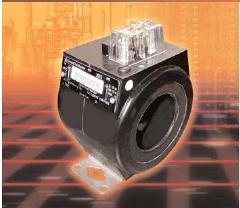
range. Typically, the wound type is insulated to Typical Bar Type Current Transformer
only 600 volts. The bushing type is typically
used around the bushing on circuit breakers and Bar type current transformers are insulated
transformers and may not have a hard protective for the operating voltage of the system.
outside cover. Bar types are available with
higher insulation levels and are usually bolted to Current transformers are applied in two very
the current caring device. different functions, metering and/or
protection.
Metering Accuracy
The accuracy class of a current transformer
is expressed as the percent error for a known
burden, current and power factor. ANSI
C57.13-1993 Table 11 defines the standard
burdens for current transformers with 5-amp
secondary. The standard percent error
expressed in Table 11 are 0.3, 0.6, and 1.2,
and the standard metering burdens are 0.1,
0.2, 0.5, 0.9 and 1.8 ohms at 60 Hz, 90%
power factor lagging. In order to study the
Typical Donut Type Current Transformer full range of normal operation, engineers
should determine the accuracy at 10% and
Donut type current transformers are typically 100% load conditions.
insulated for 600 volts. To ensure accuracy, the
conductor should be positioned in the center of As an example, a current transformer with a
the current transformer opening. meter accuracy of 0.6B0.5 would indicate a
standard burden of 0.5 ohms and a load
power factor between 0.6 and 1.0. First, at
100% primary current the error in the meter
reading due to the current transformer will
be less than +/- 0.6%. Second, at 10%
primary current the error in the meter
reading due to the current transformer will
GE Consumer & Industrial May 2008
Specification Engineer SeriesSelecting Current Transformers Part 1
be less than +/- 1.2%. The code allows the error be considered a standard accuracy current
at 10% primary current to be no more than twice transformer. Another selection might be a
the error at 100% primary current. GE ITI 785-301 300:5 current transformers
is rated as a C100. This current transformer
Relay Accuracy has a core thickness of about 6.5 inches. In a
For relay classification engineers rely on the switchgear application, one could install two
secondary terminal voltage, which the current 780-301 300:5 on each phase of the
transformer can maintain at 20 times rated switchgear; although, only one 785-301
secondary current without exceeding 10% ratio 300:5 current transformer could be installed
correction. For a 5-amp current transformer on each phase.
secondary, that would be 100-amps. ANSI
C57.13-1993 offers the following standard Many times when engineers read a
terminal voltage ratings as 10, 20, 50, 100, 200, specification that requires a 100:5 current
400, and 800 volts. ANSI C57.13 only indicated transformer and states, “all current
the current transformer is capable of supplying transformers shall have a minimum of C200
the value indicated. A current transformer with a rating,” they are puzzled as how to proceed.
50-volt rating will supply at least 50 volts but is When the specification requires a supplier to
not capable of supplying 100 volts. It may very furnish one set of current transformers for
well be able to supply 95 volts. Always calculate each of the functions shown below, it may
the actual voltage capability for the current not be possible to provide C200 rated
transformer in use. current transformers for each function:
• Transformers differential
In addition to voltage classification, ANSI • Bus differential
C57.13 assigns a letter to precede the voltage • Phase over current protection
classification. It uses a “C” or “T” to define the • Metering
manner in which the rating is established. When
the leakage reactance is low and does not have Burden
an appreciable effect on the ratio the standard The burden can be expressed in two ways.
assigns a “C” for calculated value. Bar-type and The burden can be expressed as the total
window-type current transformers, which impedance in ohms of the circuit or the total
typically have fully distributed windings, are a volt-amperes and power factor at a specified
good example of these types of current value of current or voltage and frequency.
transformers. The engineer can convert a volt-amperes
value to total impedance in ohms by
When the leakage reactance has an appreciable dividing the volt-amperes by the square of
effect on the ratio, the standard assigns a “T”. the secondary amperes. A typical calculation
The accuracy of these current transformers can would be to convert 50 volt-amperes to total
only be determined by testing. Typically, wound- impedance in ohms. Dividing 50 volt-
primary current transformers which have non- amperes by 52 (25) would be an impedance
distributed windings fit in this category. of 2 ohms.
The ability of a current transformer to produce To determine the total impedance, both
the necessary voltage classification is directly active and reactive, one must sum the
determined by the current transformer ratio. A burden of the individual devices connected
GE ITI 780-301 300:5 current transformer is to the current transformer. The individual
rated as a C20. This current transformer has a devices may only be the current transformer,
core thickness of just over three inches. It would a short run of wire and a meter. In contrast,
GE Consumer & Industrial May 2008
Specification Engineer SeriesSelecting Current Transformers Part 1
the circuit may have the current transformer, a algorithms the microprocessor relay have a
lone run of wiring, a relay, a meter, an auxiliary very small burden. In addition, the burden
current transformer and a transducer. While the does not vary with relay tap setting.
latter configuration would not be used today, one
may be required to make this calculation on an In order to determine the correct current
existing system. All manufacturers can supply transformer for the application, the engineer
the burden of their individual devices. must sum the impedances of all the devices
connected in series with the current
Although not used very often these days, transformer. Engineering studies have
induction disk over-current devices always gave shown that a sufficiently accurate value can
the burden for the minimum tap setting. To be obtained by adding the individual device
determine the impedance of the actual tap setting impedances arithmetically, which allows for
being used, first square the ratio of minimum the power factor to be ignored. If using
divide by the actual tap setting used and, second these procedures yields a borderline result, it
multiply this value by the minimum impedance. is recommended that application be avoided.
A GE IFC 51 time over-current relay (50/51
device) has an impedance of 1.47 + 5.34j at the The resistance of the terminal connection
1-amp tap. To apply the relay at the 4-amp tap may be neglected in calculating burden. In
the engineer would multiply the impedance at the applications where the wiring is confined to
1-amp tap setting by (1/4)2. The impedance at the inside of a switchgear cubical, the
the 4-amp tap would be 0.0919 + 0.3338j or engineer may neglect lead resistances.
0.3462 Z at 96.4 power factor. However, on long switchgear lineups
applying bus differential and application
Compare the GE IFC 51 over-current relay, involving outdoor switchgear lead length
which has only two functions with the GE SR- (lead resistance) should not be neglected.
750 Feeder Protection Relay with 16 current
related functions. The SR750 relay has a burden Unless a study involves the use of the
of only 0.20 VA at 5-amp input. The SR750 current transformer excitation curve, it is
burden of 0.008 ohms is 43.3 times lower than acceptable to delete the current transformer
the 0.3462 for the two function GE IFC51 relay. internal resistance. The use of ANSI
accuracy rating has already factored in the
Side Bar Note internal resistance of the current
The modern microprocessor relay takes the transformer.
analog waveform from the current transformer
and digitalizes the data before processing. To Auxiliary Current Transformers:
compensate for current transformer saturation the Because of the advent of microprocessor
microprocessor relays utilized many algorithms relays and meters, the use of auxiliary
to identify a saturation condition. Few power current transformers may not be needed. In
engineers are familiar with terms like Discrete the event an auxiliary current transformer is
Fourier transform, cosine filters, Digital Signal required, the lowest ampere-rated auxiliary
Processing, Finite Impulse Response, and current transformer that meets the circuit
MIMIC filters, just to name a few. These terms thermal requirement should be selected. By
are used to explain the operation of the selecting the lowest ampere rating, a smaller
microprocessor relay under saturated current wire can be applied, thereby allowing many
transformer conditions. Because the more turns to occupy the same space. This
microprocessor digitalizes the input current will result in a higher output voltage before
signal, and employees a host of filters and the current transformer becomes saturated.
GE Consumer & Industrial May 2008
Specification Engineer SeriesSelecting Current Transformers Part 1
To illustrate this point, when the main current from a manufactures would be GE ITI 780-
transformer is over sized and a 2-to-1 step-up of 302, 3000:5, C200, 1.105 ohms at 75 deg C.
current is required, the auxiliary current
transformer should be rated 2.5 to 5 amps. This Using the ANSI accuracy classification
is different than the 5:10 amps one would expect. assigned to a current transformer alone with
The use of auxiliary current transformers should the circuit burden impedance will offer an
be studied completely before applying in the approximate check on the selection of a
secondary of a current transformer. current transformer. This is due to the fact
that the ANSI accuracy classification is
Relay Accuracy Calculation based on a single current value. The
Engineers are required to demonstrate the standard has selected 20 times secondary
suitability of their system in order to provide current (100 amps for a 5 amp secondary)
personal and equipment safety. When it comes to with standard burdens. The following steps
relay accuracy calculation, three avenues are will outline a systematic approach to
offered. As an engineer involved only with validate the current transformer selection.
industrial power systems, I am not familiar with
“T” rated current transformer application; ANSI Accuracy Classification Step 1
therefore, my discussion will be limited to “C” Use the maximum short circuit current
rated current transformers. available from the short circuit study as a
starting point. Depending on the type of
One method, which utilizes over-current ratio- grounding, the ground fault current may be
correction curves, applies only to “T” rated different than the phase-to-phase short
current transformers. Should additional circuit current. In most cases, knowledge of
information on this subject be required, please the instantaneous and time over-current
contact the local GE sales office for a list of values is required.
names and telephone numbers.
ANSI Accuracy Classification Step 2
The remaining two methods are as follows. One Determine the impedance of all devices
method will involve the comparison of current connected in the current transformer circuit
transformer accuracy rating with the secondary at the ideal current transformer value. The
terminal voltages the current transformer can ideal secondary current is the primary
produce under all expected operating conditions. current divided by the current transformer
Another method available to the engineering ratio. In older induction disk relays, the
community requires the current transformer impedances of the instantaneous and time
secondary excitation curves to calculate the over-current function will be different.
actual ratio correction the current transformer Typically, on older induction disk relays the
will experience for a given condition. The first calculation should be preformed for
function that must be performed in any of the instantaneous, time over-current and ground
methods is to determine the total burden on the fault settings. As described earlier,
current transformer. The total ohmic burden must microprocessor relays have a single
include all relays, meters, transducers and wiring impedance value, which applies over the
resistance, when appropriate. complete range of operation. This greatly
simplifies the number of calculations
Using ANSI Accuracy Classification required to verify the suitability of the
The current transformer manufactures will current transformer in question.
supply the burden impedance, the ANSI
accuracy classification and ratio. Typically, data ANSI Accuracy Classification Step 3
GE Consumer & Industrial May 2008
Specification Engineer SeriesSelecting Current Transformers Part 1
Utilize the ANSI classification assigned to the Typical Secondary Excitation Curve
current transformer. These data are available The secondary-excitation curve shown is for
from the current transformer manufacturer. a 600:5, C200 current transformer.
ANSI Accuracy Classification Step 4 Secondary-excitation curves are available
Depending on the type of relay selected the from the current transformer manufacturer.
process will involve one or more calculations.
First, determine the total burden impedance (Zb) Using this method will require the engineer
for the current transformer secondary circuit. to obtain the actual burden impedance and
Second, calculate the current transformer actual primary current magnitude that the
secondary voltage (V’t). current transformer will measure. As a
V’t = (Ip/N) * Zb result, this method is more complex than
Ip = Primary current applying the ANSI classification for a single
N = Current transformer turn ratio fixed current magnitude. This method can
Zb = Total burden impedance indicate a current transformer is suitable for
Finally, compare V’t to the current transformer the application when the ANSI classification
rating. If the voltage rating is greater than or method demonstrated it was not suitable.
equal to the calculated secondary voltage, the Follow the four-step method to apply the
current transformer is acceptable for the secondary excitation curve calculations.
application. If V’t is greater than the ANSI
classification, additional calculations should be Step 1: Secondary-excitation
performed before rejecting the current Ascertain the maximum primary fault
transformer. current for the system under investigation.
In the absence of a completed short circuit
Using Excitation Curves study, a quick method to obtain a system’s
Engineers have another method to determine the short circuit is to sum the transformer full
suitability of a selected current transformer, load amps divided by the transformer
which method requires the use of the current impedance (transformer contribution), plus
transformer excitation curve. The method the transformer full load amps divided by
provides a more accurate assessment of the .017 (motor contribution). This will
performance by calculating the actual secondary represent the maximum expected short
current for given primary current and burden circuit value for that system. Using this
impedance. As stated earlier, this method method will provide a more realistic short
applies only to “C” classified current circuit value as opposed to using the
transformer. equipment bracing value.
Step 2: Secondary-excitation
After determining all the devices that will be
connected in series with the current
transformer, obtain the impedance for each
device and then total the impedance for this
circuit.
Step 3: Secondary-excitation
From the current transformer manufacturer,
secure the secondary excitation curve and
secondary winding resistance.
GE Consumer & Industrial May 2008
Specification Engineer SeriesSelecting Current Transformers Part 1
American National Standards Institute,
Step 4: Secondary-excitation “Requirement For Instrument
Use the conditions identified in Step 1 to Transformers”, ANSI C57.13-1999
determine the current transformer ratio
correction using the steps below: Louis Powell, “Current Transformer Burden
and Saturation”, IEEE–IAS Publication Vol
4.a Calculate the total burden impedance Zt 1A-15, No. 3
seen by the current transformer.
Dave West, “Current Transformer
4.b Determine the primary current measured Application Guide”, I&CPS Conference
by current transformer, which is labeled as Is. Record, 1977
First, in order to proceed with the calculation a
value for Ie must be assumed. A good starting W.J. Smolinski, “Design Consideration In
point would be to assume Ie is equal to zero. The Application Of Current Transformers
Based on Ie equals zero, the equation Is = Ip/N For Protective Relaying Purposes”, IEEE
becomes valid. Power Engineering Society Paper T 73 036-
1
4.c Use the equation Es = Is * Zt to calculate
the current transformer secondary voltage DW Houghtaling, “Power/Vac Metalclad
Switchgear Current Transformer
4.d Use the value for Es and the secondary Application Guide”, General Electric
excitation curve to identify a value for Ie. Company
4.e Calculate the percent excitation current General Electric Company, “Instrument
using the equations %Ie = (Ie/Is) * 100. Transformer Accuracy Standards”,
Somersworth, NH, 1971 GEC-1526B
If the percentage of Ie is negligible the
assumption of Ie = 0 in step 4.b is acceptable. General Electric Company, “Instrument
Transformer Basic Technical Information
Should the calculated value prove not to be And Application”, Somersworth, NH, 1961
negligible, return to 4.b and select another value GET-6544
for Ie and follow the same procedure again.
General Electric Company, “Instrument
Summary Transformer Burden Data”, Somersworth,
This paper has offered a window into the NH, 1961, GET1725D
complexity of selecting the correct current
transformer for the application. It will provide a
basis to go deeper into the selection procedure.
The following references list many publications
that can be used to broaden one’s knowledge.
The following papers explore in greater details
the art of selecting the correct current
transformers.
Reference:
GE Consumer & Industrial May 2008
Specification Engineer SeriesYou can also read