Service Instructions - Heat & Cool
←
→
Page content transcription
If your browser does not render page correctly, please read the page content below
Service Instructions
                                    TM

                                Goodman®
                             & Amana® Brand
                      80% Communicating Gas Furnaces
                       ACVC8, AMVC8, GCVC8, GMVC8
                               & Accessories

                                                                                       ®

This manual is to be used by qualified, professionally trained HVAC technicians only. Goodman does not assume any
responsibility for property damage or personal injury due to improper service procedures or services performed by
an unqualified person.
The material in this manual does not supercede manufacturer’s installation and operation instructions.

           ®
               is a registered trademark of Maytag Corporation or its related companies and is used under license.      RS6620001
           ®

                                               All rights reserved.                                                  November 2016
                                         Copyright © 2016 Goodman Manufacturing Company, L.P.
TABLE OF CONTENTS
IMPORTANT INFORMATION ......................... 2 - 4                    SYSTEM OPERATION COMFORTNET™ ...52 - 57
PRODUCT IDENTIFICATION ...................... 5 - 10                     POLARIZATION AND PHASING ........................ 58
ACCESSORIES ..........................................11 - 12            MAINTENANCE ...........................................59 - 61
OPERATING INSTRUCTIONS ...................13 - 15                        SERVICING .................................................62 - 80
PRODUCT DESIGN ...................................16 - 41                SERVICING TABLE OF CONTENTS ................ 62
SYSTEM OPERATION ...............................42 - 45                  ACCESSORY WIRING DIAGRAMS .............81- 82
TROUBLESHOOTING ................................46 - 51                  WIRING DIAGRAMS..................................... 83- 85

IMPORTANT INFORMATION
Pride and workmanship go into every product to provide our customers with quality products. It is possible, however,
that during its lifetime a product may require service. Products should be serviced only by a qualified service technician
who is familiar with the safety procedures required in the repair and who is equipped with the proper tools, parts, testing
instruments and the appropriate service manual. REVIEW ALL SERVICE INFORMATION IN THE APPROPRIATE
SERVICE MANUAL BEFORE BEGINNING REPAIRS.

              IMPORTANT NOTICES FOR CONSUMERS AND SERVICERS

                                      RECOGNIZE SAFETY SYMBOLS, WORDS AND LABELS

                                                                                                         WARNING
ONLY PERSONNEL THAT HAVE BEEN TRAINED TO INSTALL, ADJUST, SERVICE OR
                                                                          TO PREVENT THE RISK OF PROPERTY DAMAGE, PERSONAL    INJURY, OR DEATH,
REPAIR ( HEREINAFTER, “SERVICE”) THE EQUIPMENT SPECIFIED IN THIS
                                                                          DO NOT STORE COMBUSTIBLE MATERIALS OR USE GASOLINE OR OTHER
MANUAL SHOULD SERVICE THE EQUIPMENT. THE MANUFACTURER WILL NOT            FLAMMABLE LIQUIDS OR VAPORS IN THE VICINITY OF THIS APPLIANCE.
BE RESPONSIBLE FOR ANY INJURY OR PROPERTY DAMAGE ARISING FROM
IMPROPER SERVICE OR SERVICE PROCEDURES. IF YOU SERVICE THIS UNIT, YOU
ASSUME RESPONSIBILITY FOR ANY INJURY OR PROPERTY DAMAGE WHICH MAY
RESULT. IN ADDITION, IN JURISDICTIONS THAT REQUIRE ONE OR MORE
LICENSES TO SERVICE THE EQUIPMENT SPECIFIED IN THIS MANUAL, ONLY
LICENSED PERSONNEL SHOULD SERVICE THE EQUIPMENT. IMPROPER
INSTALLATION, ADJUSTMENT, SERVICING OR REPAIR OF THE EQUIPMENT
SPECIFIED IN THIS MANUAL, OR ATTEMPTING TO INSTALL, ADJUST, SERVICE OR
REPAIR THE EQUIPMENT SPECIFIED IN THIS MANUAL WITHOUT PROPER
TRAINING MAY RESULT IN PRODUCT DAMAGE, PROPERTY DAMAGE, PERSONAL
INJURY OR DEATH.

                                                                     WARNING
                                      HIGH VOLTAGE
                                      DISCONNECT ALL POWER BEFORE SERVICING OR
                                      INSTALLING THIS UNIT. MULTIPLE POWER SOURCES MAY
                                      BE PRESENT. FAILURE TO DO SO MAY CAUSE PROPERTY
                                      DAMAGE, PERSONAL INJURY OR DEATH.

2
IMPORTANT INFORMATION
To locate an authorized servicer, please consult your telephone book or the dealer from whom you purchased this
product. For further assistance, please contact:
CONSUMER INFORMATION LINE CONSUMER INFORMATION LINE
GOODMAN® BRAND PRODUCTS AMANA® BRAND PRODUCTS
TOLL FREE TOLL FREE
1-877-254-4729 (U.S. only) 1-877-254-4729 (U.S. only)
email us at: email us at:
customerservice@goodmanmfg.com hac.consumer.affairs@amanahvac.com
fax us at: (731) 856-1821 fax us at: (731) 856-1821
(Not a technical assistance line for dealers.) (Not a technical assistance line for dealers.)
Outside the U.S., call 1-713-861-2500.
(Not a technical assistance line for dealers.) Your telephone company will bill you for the call.
3IMPORTANT INFORMATION
CO can cause serious illness including permanent brain
damage or death. B10259-216
Advertencia especial para la instalación de calentadores ó manejadoras
de aire en áreas cerradas como estacionamientos ó cuartos de servicio.
Las emisiones de monóxido de carbono pueden circular a través
del aparato cuando se opera en cualquier modo.
El monóxido de carbono puede causar enfermedades severas
como daño cerebral permanente ó muerte. B10259-216
RISQUE D'EMPOISONNEMENT AU MONOXYDE DE CARBONE
Cette ventilation est nécessaire pour éviter le danger d'intoxication
au CO pouvant survenir si un appareil produisant du monoxyde
de carbone continue de fonctionner au sein de la zone confinée.
B10259-216
4PRODUCT IDENTIFICATION
The model and manufacturing number are used for positive identification of component parts used in manufacturing.
Please use these numbers when requesting service or parts information.
G M V C 8 0 0 6 0 3 B N A A
1 2 3 4 5 6 7 8 9 10 11 12 13 14
Brand Minor Revision
G- Goodman A - Initial Release
B - 1st Revision
Configuration
M - Upflow/Horizontal Major Revision
C - Downflow/Horizontal A - Initial Release
B - 1st Revision
Motor
V - Variable Speed/ComfortNet Nox
N - Natural Gas
Gas Valve X - Low NOx
M - Modulating
C - 2 Stage Cabinet Width
A - 14"
AFUE B - 17.5"
97 - 97% AFUE C - 21"
80 - 80% AFUE D - 24.5"
MBTU/h Maximum CFM
40 - 40,000 3 - 1200 CFM
60 - 60,000 4 - 1600 CFM
80 - 80,000 5 - 2000 CFM
100 - 100,000
120 - 120,000
A M V C 8 0 0 6 0 3 B N A A
1 2 3 4 5 6 7 8 9 10 11 12 13 14
Brand Minor Revision
A- Amana® A - Initial Release
B - 1st Revision
Configuration
M - Upflow/Horizontal Major Revision
C - Downflow/Horizontal A - Initial Release
K - Dedicated Upflow B - 1st Revision
Nox
Motor N - Natural Gas
V - Variable Speed/ComfortNet X - Low NOx
E - High Efficiency
S - Single Speed Cabinet Width
A - 14"
Gas Valve B - 17.5"
M - Modulating C - 21"
C - 2 Stage D - 24.5"
H - Convertible 2 Stage
S - Single Stage Maximum CFM
3 - 1200 CFM
AFUE 4 - 1600 CFM
97 - 97% AFUE 5 - 2000 CFM
80 - 80% AFUE
MBTU/h
40 - 40,000
60 - 60,000
80 - 80,000
100 - 100,000
120 - 120,000
5PRODUCT IDENTIFICATION
MODEL # MFG # DESCRIPTION
GMVC80603B*BC
GMVC80604B*BC
GMVC80803B*BC Goodman® Brand 80% communicating capable furnace, firing at 20,000 BTUH per burner, 33 3/8" tall, UPflow /
GMVC8***BC GMVC80804C*BC Horizontal installation positions, 2 stage gas heat, supports 2 stage cooling, induced draft. 4 wire serially
GMVC80805C*BC communicating ECM motor. 120 volt silicon nitride igniter. L eft or Right gas pipe entry. Models are low
GMVC80805D*BC NOx. Aluminized Steel tubular heat exchanger . Available cabinet widths 17.5"and 21.
GMVC81005C*BC
GCVC80603BXBC Goodman® Brand 80% communicating capable furnace, firing at 20,000 BTUH per burner, 33 3/8" tall, Downflow /
GCVC80803BXBC Horizontal installation positions, 2 stage gas heat, supports 2 stage cooling, induced draft. 4 wire serially
GCVC8***BC
GCVC80805CXBC communicating ECM motor. 120 volt silicon nitride igniter. L eft or Right gas pipe entry. Models are low
GCVC81005CXBC NOx. Aluminized Steel tubular heat exchanger . Available cabinet widths 17.5"and 21.
AMVC80603B*BC
AMVC80604B*BC
AMVC80803B*BC Amana® Brand 80% communicating capable furnace, firing at 20,000 BTUH per burner, 33 3/8" tall, UPflow /
AMVC8***BC AMVC80804C*BC Horizontal installation positions, 2 stage gas heat, supports 2 stage cooling, induced draft. 4 wire serially
AMVC80805C*BC communicating ECM motor. 120 volt silicon nitride igniter. L eft or Right gas pipe entry. Models are low
AMVC80805D*BC NOx. Stainless steel tubular heat exchanger . Available cabinet widths 17.5"and 21.
AMVC81005C*BC
ACVC80603BXBC Amana® Brand 80% communicating capable furnace, firing at 20,000 BTUH per burner, 33 3/8" tall, Downflow /
ACVC80803BXBC Horizontal installation positions, 2 stage gas heat, supports 2 stage cooling, induced draft. 4 wire serially
ACVC8***BC
ACVC80805CXBC communicating ECM motor. 120 volt silicon nitride igniter. L eft or Right gas pipe entry. Models are low
ACVC81005CXBC NOx. Stainless steel tubular heat exchanger . Available cabinet widths 17.5"and 21.
6PRODUCT IDENTIFICATION
MODEL # MFG # DESCRIPTION
Fossil Fuel Kit - The AFE18-60A control is designed for use where the indoor coil is located
above/downstream of a gas or fossil fuel furnace when used with a heat pump. It will operate
AFE18-60A N/A with single and two stage heat pumps and single and two stage furnaces. The AFE18-60A
control will turn the heat pump unit off when the furnace is turned on. An anti-short cycle
feature initiates a 3 minute timed off delay when the compressor goes off.
Communicating Thermostat Kit - Digitally communicating touchscreen thermostat, a
necessary part of any communicating system. Designed for use with compatible Air
Handlers or Furnaces and outdoor split AC or Heat Pump units. This thermostat supports up
to three stages of heat, two stages of cooling, dual fuel applications, dehumidification, filter
CTK01AA CTK01AA
maintenance reminders, outdoor temperature display and advanced menus including
diagnostics. The CTK01AA kit includes a communicating touchscreen thermostat and sub
base, 230V-24V 40va transformer, terminal blocks (2), wire jumpers, mounting screws,
installation manual and homeowner guide.
Communicating Thermostat Kit - Digitally communicating touchscreen thermostat, a
necessary part of any communicating system. Designed for use with compatible Air
Handlers or Furnaces and outdoor split AC or Heat Pump units. This thermostat supports up
CTK01BA CTK01BA to three stages of heat, two stages of cooling, dual fuel applications, dehumidification, filter
maintenance reminders, outdoor temperature display and advanced menus including
diagnostics. The CTK01BA kit includes a communicating touchscreen thermostat and sub
base, terminal blocks (2), installation manual and homeowner guide.
Communicating Thermostat Kit - Digitally communicating thermostat, a necessary part of
any communicating system. Designed for use with compatible Air Handlers or Furnaces and
outdoor split AC or Heat Pump units. The CTK02** thermostat features a full color high
CTK02** CTK02** definition display, advanced programming options including humidification control & heat
and cool maximum temperature settings, a USB plug allowing dealers the ability to insert
programmed operating parameters and dealer information by use of an online data entry
system.
Communicating Thermostat Kit - Digitally communicating touchscreen thermostat from
Honeywell. Designed for use with compatible Air Handlers or Furnaces and outdoor split AC
CTK03AA CTK03AA
or Heat Pump units. The CTK03AA thermostat features full color high definition display and
can be used with RedLINK wireless accessories.
Communicating Thermostat Kit - Digitally communicating touchscreen thermostat from
Honeywell. Designed for use with compatible Amana ® Brand or Goodman ® Brand Air
Handlers or Furnaces and outdoor split AC or Heat Pump units. The CTK03AB thermostat
CTK03AB CTK03AB
Features full color high definition display and can be used with RedLINK wireless
accessories and added capability to control the HUN IN - HUM OUT relay on the PCBKF103,
PCBKF104, and PCBKF105 control board.
7PRODUCT IDENTIFICATION
MODEL # MFG # DESCRIPTION
Dehumidistat. Wall mou nted, 24 volt hu midity control available as a Dehumidistat used to
reduce the airflow in th e air conditioning mode to lower the humidity in an occupied home. This
DEHUM1 P1227801F control features a moisture-sen sitive nylon element and also provides positive On-Off settings
for manual operatio n. The control i s a normally cl osed switch that opens on humidity rise
causing the blower to switch to a lower spe ed to control the humidity within the structure.
External Filter Rack Kit. For u se with upflow gas fu rnace models. This kit is i ntended to provi de
P1221001 a location, external to the furnace casing, for installation of a permanent filter. The rack is
EFR01
P1221002F mounted over the ind oor air blower compartment area of either side panel, and p rovide filter
retention as well as l ocation for attaching return air ductwork.
High Altitude Kit. The kit is desi gned to convert 80% gas furnace models at higher alti tudes.
This ki t is required when installing these furnace s above their maximum rated altitude. This kit
HA02 P1129112F contains # 43-49, 55-58 gas orfices. The orfice s in the kit have been sele cted as a result of
testing with the American Gas Association. they will provide appropriate derating at the altitude
liste d in the High Altitude Charts as shown in the i nstallation instructions of the kit.
MODEL # MFG # DESCRIPTION
LP Gas Low Pressure Kit.For use with furnaces converted to LP gas. This kit includes
LPLP03 N/A harness adaptors to work with White-Rodgers single & two stage gas valves, Honeywell
single and two-stage gas valves, as well as modulating gas valves.
LP Conversion Kit. For use with 2-stage models using a White-Rodgers 36G54 2-stage
LPM-06 N/A gas valve kit or a Honeywell VR9205 2-stage gas valve kit. Includes regulator springs,
#55 orifices, instructions and lable to show the furnace has been converted to L.P.
SBT17
Downflow Subbase. For use with 80% Counterflow furnace models. These kits are
SBT21 N/A
available for the following furnace widths: 17.5" wide (SBT17), 21" wide (SBT21)
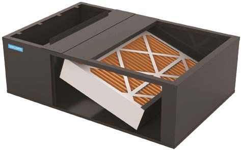
8ACCESSORIES
EXTERNAL FILTER RACK KIT
( EFR01 )
SLOTS IN FILTER
CLEAR SCREWS
ON UNIT
BLOWER DECK
SCREWS
UNIT SIDE
PANEL
FRONT
OF UNIT
FILTER RACK ASSEMBLY
(FACE FILTER OPENING
BASE TOWARDS FRONT
OF UNIT OF UNIT)
RETURN AIR
CUTOUT AREA
LOWER EDGE
SCREW
EFR01 EXTERNAL FILTER RACK KIT
Used on Models
80% Upflow Model Furnaces
9ACCESSORIES
AFE180-60A
Model
DEHUM1
LPLP03
LPM06
EFR01
SBT17
SBT21
HA-02
CTK0*
Number
High Altitude Natural
Downflow Subbase
Downflow Subbase
EFR External Filter
LP Low Pressure
Dual Fuel Board
Communicating
Conversion Kit
Dehumidistat
Propane Gas
Gas Orifices
Shut Off Kit
Thermostat
Rack
17.5"
21"
Description
*MVC80603B ● ● ● (1) ● (2) ●
*MVC80604B ● ● ● (1) ● (2) ●
*MVC80803B ● ● ● (1) ● (2) ●
*MVC80804C ● ● ● (1) ● (2) ●
*MVC80805C ● ● ● (1) ● (2) ●
*MVC80805D ● ● ● (1) ● (2) ●
*MVC80805C ● ● ● (1) ● (2) ●
*CVC80603B ● ● ● (1) ● (2) ●
*CVC80803B ● ● ● (1) ● (2) ●
*CVC80805C ● ● ● (1) ● (2) ●
*CVC81005C ● ● ● (1) ● (2) ●
Not Approved for this model
● Approved for this model
(1) W/R and HW 2 stage valves
(2) 7,000 - 11,000 FT altitude
10OPERATING INSTRUCTIONS
FOR YOUR SAFETY READ BEFORE OPERATING
WARNING: Improper
If you do not follow these instructions exactly,
a fire or explosion may result causing property alteration, service or
damage, personal injury or loss of life. maintenance can
cause injury or
property damage.
A. This appliance does not have a pilot. It If you cannot reach your gas supplier, Refer to the user's
is equipped with an ignition device which call the fire department. information manual
automatically lights the burners. Do not provided with this
try to light the burners by hand. C. Use only your hand to move the gas
control switch or knob. Never use
B. BEFORE OPERATING smell around tools. If the gas control switch or knob
the appliance area for gas. Be sure to will not operate, don't try to repair it, consult a qualified
smell next to the floor because some gas call a qualified service technician.
is heavier than air and will settle on the Force or attempted repair may result in or the gas supplier.
floor. a fire or explosion.
WHAT TO DO IF YOU SMELL GAS
Do not try to light any appliance. D. Do not use this appliance if any part This furnace must be
Do not touch any electric switch; has been under water. Immediately call
do not use any telephone in your a qualified service technician to inspect
building. the appliance and to replace any part of instructions and local
Immediately call your supplier the control system and any gas control codes. In the absence
from a neighbor's phone. Follow which has been under water. of local codes, follow
the gas suppliers instructions. the National Fuel Gas
Code, ANSI Z223.1.
OPERATING INSTRUCTIONS
1. STOP! Read the safety information 7. Wait five (5) minutes to clear out any For indoor installation.
above on this label. gas. If you then smell gas, STOP!
Follow "B" in the safety information PGB & PGJ
2. Set the thermostat to lowest setting. above on this label. If you don't smell For outdoor
3. Turn off all electric power to the gas, go to the next step. installation only.
appliance. 8. Move the gas control switch or knob
4. This appliance is equipped with an to "ON".
automatic ignition system which 9. Replace control access panel. WARNING: If not
automatically lights the burners. Do not installed, operated
try to light the burners by hand. 10. Turn on all electric power to the and maintained in
appliance. accordance with the
5. Remove control access panel.
11. Set the thermostat to the desired manufacturer's
6. Move the gas control switch or knob setting. instructions, this
to "OFF". product could expose
12. If the appliance will not operate, you to substances
follow the instructions "To Turn Off Gas in fuel combustion
To Appliance" and call your service
technician or gas supplier. which can cause
death or serious
illness and which
are known to the
State of California to
GAS CONTROL cause cancer, birth
SWITCH SHOWN
IN "ON" POSITION
defects or other
reproductive harm.
This product contains
TO TURN OFF GAS TO APPLIANCE fiberglass insulation.
Fiberglass insulation
1. Set the thermostat to its lowest setting. 4. Move the gas control switch or knob contains a chemical
2. Turn off all electric power to the to "OFF". Do not force.
California to cause
appliance if service is to be performed. 5. Replace control access panel. cancer.
3. Remove control access panel.
FOR YOUR SAFETY Do not store or use gasoline or
other flammable vapors and liquids in the vicinity of this
or any other appliance. 0140F00001P
11OPERATING INSTRUCTIONS
CONSIGNES DE SECURITE - LIRE INSTRUCTIONS DE SERVICE
AVANT D'ALLUMER L'APPAREIL 1. UN INSTANT! Lisez d'abord les consignes
de securite ci-dessus.
AVERTISSEMENT: Le non-respect des instructions qui suivent peut 2. Reglez le thermostat a son point le plus bas.
3. Coupez l'alimentation electrique de l'appareil.
entrainer
^
un risque d'incendie ou d'explosion causant des dommages, 4. Cet appareil est muni d'un mecanisme qui
des blessures ou la mort. allume automatiquement le bruleur.
^
Ne tentez
pas d'allumer le bruleur
^
manuellement.
A. Cet appareil comporte pas de veilleuse. Il est muni d'un mecanisme qui allume 5. Retirez le panneau d'acces de la commande.
^
automatiquement le bruleur. ^
N'allumez paz le bruleur manuellement. 6. Mettez la commande de gaz a la position
^
ARRET ("OFF").
B. Sentir tout autour de l'appariel AVANT D'ALLUMER afin de deceler toute fuite de gaz. 7. Attendez cinq (5) minutes afin de permettre a
Assurez-vous de sentir tout pres du plancher car certains gaz sont plus lourds que l'air tout gaz present d'etre
^
evacue. Si vous sentez
et se deposeront sur le plancher. une odeur de gaz a ce moment, ARRETEZ! ^
et
suivez les consignes de securite donnees au
SI VOUS SENTEZ UNE ODEUR DE GAZ: paragraphe B ci-dessus. Si vous ne sentez pas Commande de
Ne tentez d'allumer aucun appariel. de gaz, passez a l'etape suivante. gaz en position
Ne touchez pas aux interrupteurs electriques; n'utiliser aucun telephone 8. Mettez la commande de gaz a la position "MARCHE"
dans l'edifice ou vous vous trouvez. MARCHE ("ON").
Appelez immediatement votre fournisseur de gaz en utilisant le telephone 9. Remettez la panneau d'acces de la commande
d'un voisin et suivez les instructions du fournisseur. en place.
Appelez les pompiers si vous ne parvenez pas a rejoindre votre fournisseur 10. Retablissez l'alimenation electrique de l'appareil.
de gaz. 11. Reglez le thermostat a le temperature desiree.
12. Si l'appareil ne fonctionne pas, suivez les
C. N'utiliser que votre main pour pousser ou tourner le commande du gaz. N'utilisez ^
instructions intitulees "Arret du gaz" et appelez un
jamais d'outils. Si vous ne parvenez pas a pousser ou a tourner la commande, ne tentez reparateur qualifie ou votre fournisseur de gaz.
pas de la reparer; appelez un reparateur qualifie. Forcer la commande ou essayer de la ^
reparer peut entrainer
^
un risque d'incendie ou d'explosion. ARRET DU GAZ
1. Reglez le thermostat a son point le plus bas.
D. N'utilisez pas cet appareil si l'une de ses parties a ete dans l'eau. Si cela se produit,
2. Coupez l'alimentation electrique de l'appareil si vous devez effectuer un entretien.
demandez immediatement a un reparateur qualifie d'inspecter l'appareil et de remplacer
3. Retirez le panneau d'acces de la commande.
toute piece du systeme de controle ^
et toute commande de gaz ayant ete dans l'eau. ^
4. Mettez la commande de gaz a la position ARRET ("OFF").
0140F00002P 5. Remettez le panneau d'acces de la commande en place.
12OPERATING INSTRUCTIONS
ROBINET A GAZ
MANUEL, EN POS
"ON/MARCHE"
GAS
INLET
ARRIVEE
DU GAZ
MANUAL GAS
LEVER SHOWN
IN "ON" POS
13PRODUCT DESIGN
Safety Product Application
Please adhere to the following warnings and cautions when This product is designed for use as a residential home gas
installing, adjusting, altering, servicing, or operating the fur- furnace. It is not designed or certified for use in mobile home,
nace. trailer, or recreational vehicle applications.
This furnace can be used in the following non-industrial
commercial applications: Schools, Office buildings, Churches,
WARNING Retail stores, Nursing homes, Hotels/motels, Common or
office areas. In such applications, the furnace must be installed
TO PREVENT PERSONAL INJURY OR DEATH DUE TO IMPROPER INSTALLATION, with the installation instructions.
ADJUSTMENT, ALTERATION, SERVICE OR MAINTENANCE, REFER TO THIS
MANUAL. FOR ADDITIONAL ASSISTANCE OR INFORMATION, CONSULT A Goodman & Amana® 80% furnaces are ETL certified appli-
QUALIFIED INSTALLER, SERVICE AGENCY OR THE GAS SUPPLIER. ances and are appropriate for use with natural or propane
gas. (NOTE: If using propane gas, a propane conversion kit
is required).
WARNING
IMPORTANT NOTE: The 80% furnace cannot be installed
THIS PRODUCT CONTAINS OR PRODUCES A CHEMICAL OR CHEMICALS WHICH as a direct vent (i.e.., sealed combustion) furnace. The
MAY CAUSE SERIOUS ILLNESS OR DEATH AND WHICH ARE KNOWN TO THE burner box is present only to help reduce sound trans-
STATE OF CALIFORNIA TO CAUSE CANCER, BIRTH DEFECTS OR OTHER mission from the burners to the occupied space.
REPRODUCTIVE HARM.
To ensure proper installation, operation and servicing, thor-
oughly read the installation and service manuals for specif-
ics pertaining to the installation, servicing and application of
WARNING this product.
TO PREVENT POSSIBLE PROPERTY DAMAGE, PERSONAL INJURY OR DEATH
DUE TO ELECTRICAL SHOCK, THE FURNACE MUST BE LOCATED TO PROTECT
WARNING
THE ELECTRICAL COMPONENTS FROM WATER.
POSSIBLE PROPERTY DAMAGE, PERSONAL INJURY OR DEATH DUE TO FIRE,
Charge (ESD) Precautions EXPLOSION, SMOKE, SOOT, CONDENSTAION, ELECTRICAL SHOCK OR CARBON
NOTE: Discharge body’s static electricity before touching MONOXIDE MAY RESULT FROM IMPROPER INSTALLATION, REPAIR, OPERATION,
unit. An electrostatic discharge can adversely affect electri- OR MAINTENANCE OF THIS PRODUCT.
cal components.
Use the following precautions during furnace installation and
servicing to protect the integrated control module from dam- WARNING
age. By putting the furnace, the control, and the person at
the same electrostatic potential, these steps will help avoid TO PREVENT PROPERTY DAMAGE, PERSONAL INJURY OR DEATH DUE TO FIRE,
exposing the integrated control module to electrostatic dis- DO NOT INSTALL THIS FURNACE IN A MOBILE HOME, TRAILER, OR RECREATIONAL
VEHICLE.
charge. This procedure is applicable to both installed and
uninstalled (ungrounded) furnaces. To ensure proper furnace operation, install, operate, main-
1. Disconnect all power to the furnace. Do not touch the tain and service the furnace in accordance with the installa-
integrated control module or any wire connected to the tion, operation and service instructions, all local building
control prior to discharging your body’s electrostatic codes and ordinances. In their absence, follow the latest
charge to ground. edition of the National Fuel Gas Code (NFPA 54/ANSI
2. Firmly touch a clean, unpainted, metal surface of the Z223.1), and/or CAN/CGA B149 Installation Codes, local
furnace near the control. Any tools held in a person’s plumbing or waste water codes, and other applicable codes.
hand during grounding will be discharged. A copy of the National Fuel Gas Code (NFPA 54/ANSI
3. Service integrated control module or connecting wiring Z223.1) can be obtained from any of the following:
following the discharge process in Step 2. Use caution
not to recharge your body with static electricity; (i.e., do American National Standards Institute
not move or shuffle your feet, do not touch ungrounded
25 West 43rd Street, 4th Floor
objects, etc.). If you come in contact with an ungrounded
object, repeat Step 2 before touching control or wires. New York, NY 10036
4. Discharge any static electricity from your body to ground
before removing a new control from its container. Follow National Fire Protection Association
Steps 1 through 3 if installing the control on a furnace. 1 Batterymarch Park
Return any old or new controls to their containers before Quincy, MA 02169-7471
touching any ungrounded object.
14PRODUCT DESIGN
CSA International tible material (including wood). Refer to subbase in-
8501 East Pleasant Valley structions for installation details. (NOTE: A subbase
Cleveland, OH 44131 will not be required if an air conditioning coil is located
beneath the furnace between the supply air opening
and the combustible floor.
A copy of the CAN/CGA B149 Installation Codes can be
• Exposure to contaminated combustion air will result
obtained from:
in safety and performance-related problems. Do not
CSA International install the furnace where the combustion air is ex-
178 Rexdale Boulevard posed to the following substances:
Etobicoke, Ontario, Canada M9W, 1R3 chlorinated waxes or cleaners
chlorine-based swimming pool chemicals
The rated heating capacity of the furnace should be greater water softening chemicals
than or equal to the total heat loss of the area to be heated. deicing salts or chemicals
The total heat loss should be calculated by an approved
carbon tetrachloride
method or in accordance with “ASHRAE Guide” or “Manual
J-Load Calculations” published by the Air Conditioning Con- halogen type refrigerants
tractors of America. cleaning solutions (such as perchloroethylene)
printing inks
Location Requirements and Considerations paint removers
varnishes
WARNING hydrochloric acid
cements and glues
TO PREVENT POSSIBLE EQUIPMENT DAMAGE, PROPERTY DAMAGE, PERSONAL
INJURY OR DEATH, THE FOLLOWING BULLET POINTS MUST BE OBSERVED antistatic fabric softeners for clothes dryers
WHEN INSTALLING THE UNIT. and masonry acid washing materials
Follow the instructions listed below when selecting a fur- • To ensure that the enclosed non-direct vent furnace
nace location. Refer also to the guidelines provided in the has an adequate supply of combustion air, vent from
Combustion and Ventilation Air Requirements section in this a nearby uncontaminated room or from outdoors. Re-
manual or the installation instructions for details. fer to the Combustion and Ventilation Air Require-
• Centrally locate the furnace with respect to the pro- ments section in this manual or the installation in-
posed or existing air distribution system. structions for details.
• Ensure the temperature of the return air entering the • If the furnace is used in connection with a cooling
furnace is between 55°F and 100°F when the furnace unit, install the furnace upstream or in parallel with
is heating. the cooling unit coil. Premature heat exchanger fail-
ure will result if the cooling unit coil is placed ahead of
• If the furnace is installed in an application where the
the furnace.
typical operating sound level of a furnace is deemed
objectionable, an optional sound reduction kit is avail- • If the furnace is installed in a residential garage, posi-
able. Consult your local distributor for more details. tion the furnace so that the burners and ignition source
are located not less than 18 inches (457 mm) above
• Provide provisions for venting combustion products
the floor. Protect the furnace from physical damage
outdoors through a proper venting system. Special
by vehicles.
consideration should be given to vent/flue pipe routing
and combustion air intake pipe when applicable. • If the furnace is installed horizontally, the furnace ac-
cess doors must be vertical so that the burners fire
80% Furnaces: All installations must be vented in
horizontally into the heat exchanger. Do not install
accordance with National Fuel Gas Code, NFPA 54/
the unit with the access doors on the “up/top” or “down/
ANSI Z223.1 - lateset edition. In Canada the furnaces
bottom” side of the furnace.
must be vented in accordance with the National Stan-
dard of Canada, CAN/CGA B149.
Clearances and Accessibility
• Ensure upflow or horizontal furnaces are not installed Installations must adhere to the clearances to combustible
directly on carpeting, or any other combustible mate- materials to which this furnace has been design certified.
rial. The only combustible material allowed is wood. The minimum clearance information for this furnace is pro-
• A special accessory subbase must be used for up- vided on the unit’s clearance label. These clearances must
right counterflow unit installations over any combus- be permanently maintained. Refer to Specification Sheet for
minimum clearances to combustible materials. Clearances
15PRODUCT DESIGN
must also accommodate an installation’s gas, electrical, that there is no blockage or restriction, leakage, corrosion and other
and drain trap and drain line connections. NOTE: In addition deficiencies which could cause an unsafe condition;
to the required clearances to combustible materials, a mini- c. In so far as practical, close all building doors and windows and all
mum of 24 inches service clearance must be available in doors between the space in which the appliance(s) connected to
front of the unit. the venting system are located and other spaces of the building.
Turn on clothes dryers and any appliance not connected to the
A furnace installed in a confined space (i.e., a closet or
venting system. Turn on any exhaust fans, such as range hoods
utility room) must have two ventilation openings with a total and bathroom exhausts, so they shall operate at maximum speed.
minimum free area of 0.25 square inches per 1,000 BTU/hr Do not operate a summer exhaust fan. Close fireplace dampers;
of furnace input rating. One of the ventilation openings must d. Follow the lighting instructions. Place the appliance being in-
be within 12 inches of the top; the other opening must be spected in operation. Adjust thermostat so appliance shall oper-
within 12 inches of the bottom of the confined space. In a ate continuously;
typical construction, the clearance between the door and e. Test for draft hood equipped spillage at the draft hood relief
door frame is usually adequate to satisfy this ventilation re- opening after 5 minutes of main burner operation. Use the flame
quirement. of a match or candle;
f. After it has been determined that each appliance connected to the
Furnace Suspension venting system properly vents when tested as outlined above,
If suspending the furnace from rafters or joist, use 3/8" return doors, windows, exhaust fans, fireplace dampers and any
threaded rod and 2”x2”x1/8” angle iron as shown in the fol- other gas burning appliance to their previous conditions of use;
lowing figure. If the furnace is installed in a crawl space it g. If improper venting is observed during any of the above tests, the
must also be suspended from the floor joist or supported by common venting system must be corrected.
a concrete pad. Never install the furnace on the ground or Corrections must be in accordance with the latest edition of
allow it to be exposed to water. The length of rod will depend the National Fuel Gas Code NFPA 54/ANSI Z223.1 and/or
on the application and the clearances necessary. CSA B149 Installation Codes.
PROVIDE 8" MINIMUM CLEARANCE BETWEEN If resizing is required on any portion of the venting system,
CENTER ROD AND FURNACE CABINET
TO ALLOW FOR CIRCULATOR BLOWER REMOVAL.
use the appropriate table in Appendix G in the latest edition
3/8" DIAMETER ALTERNATE ASSURE FURNACE IS LEVEL FROM
of the National Fuel Gas Code ANSI Z223.1 and/or CSA B149
THREADED ROD GAS PIPING END TO END.
ON 90% FURNACES MAKE SURE
Installation Codes.
(6 PLACES)
THE UNIT HAS A SLIGHT
FORWARD TILT WITH THE FRONT
Thermostat Requirements
HOLD DOWN
OF THE FURNACE 0"-3/4"
BELOW THE BACK OF THE FURNACE.
NOTE: A single-stage thermostat with only one heating stage
NUTS
may be used to control ComfortNet™ compatible furnaces.
SUPPORT
NUTS
The application of a single-stage thermostat does not offer
“true” thermostat-driven two-stage operation, but provides a
timed transition from low to high fire. The furnace will run on
CONDENSATE
GAS PIPING DRAIN low stage for a fixed period of time before stepping up to
high stage to satisfy the thermostat’s call for heat. The
2"X2"X1/8" ANGLE IRON delay period prior to stepping up can be set at either a fixed
(3 PLACES)
POSITION AS CLOSE AS POSSIBLE
TILT OUTWARD TO ALLOW FOR
DOOR AND CIRCULATOR BLOWER 5 minute time delay or a load based variable time between 1
TO BLOWER DECK TO ALLOW FOR
CIRCULATOR BLOWER REMOVAL.
REMOVAL.
and 12 minutes (AUTO mode). If the AUTOmode is selected,
the control averages the cycle times of the previous three
90% Suspended Furnace Shown cycles and uses the average to determine the time to transi-
(80% Furnace Similar) tion from low stage to high stage.
EXISTING FURNACE REMOVAL To use a single-stage thermostat, turn off power to the fur-
NOTE: When an existing furnace is removed from a venting nace, move the thermostat selection DIP switch to the OFF
system serving other appliances, the venting system may position. Set the desired transition time by setting the tran-
be too large to properly vent the remaining attached appli- sition delay DIP switch to the desired ON/OFF position. Turn
ances. power back on. Refer to the following figure.
The following vent testing procedure is reproduced from the
American National Standard/National Standard of Canada for
Gas-Fired Central Furnaces ANSI Z21.47, latest edition,
CSA-2.3b, latest edition Section 1.23.1.
The following steps shall be followed with each appliance connected to
the venting system placed in operation, while any other appliances
connected to the venting system are not in operation:
a. Seal any unused openings in the venting system;
b. Inspect the venting system for proper size and horizontal pitch,
as required by the National Fuel Gas Code, ANSI Z223.1 or the
CSA B149 Installation Codes and these instructions. Determine
16PRODUCT DESIGN
OFF ON COMBUSTION AND VENTILATION AIR
Heat OFF Delay Move to the ON position
DIP Switches to select two-stage REQUIREMENTS
thermostat or OFF to
select single stage
thermostat
3 Thermostat WARNING
4 Stage Delay
Move to the ON position POSSIBLE PROPERTY DAMAGE, PERSONAL INJURY OR DEATH MAY OCCUR
S1 to select Auto transition IF THE FURNACE IS NOT PROVIDED WITH ENOUGH FRESH AIR FOR PROPER
delay or OFF for 5 minute
transition delay COMBUSTION AND VENTILATION OF FLUE GASES. MOST HOMES REQUIRE
OUTSIDE AIR BE SUPPLIED TO THE FURNACE AREA.
Dehumidistat Requirements Improved construction and additional insulation in buildings
A dehumidistat can be used in conjunction with the two- have reduced heat loss by reducing air infiltration and es-
stage variable speed furnace to lower the humidity in the cape around doors and windows. These changes have helped
conditioned space. The dehumidistat will improve dehumidi- in reducing heating/cooling costs but have created a prob-
fication of the conditioned air by prompting the furnace to lem supplying combustion and ventilation air for gas fired
reduce the speed of the circulator blower during operation in and other fuel burning appliances. Appliances that pull air
the cooling mode. To be compatible with these furnaces, a out of the house (clothes dryers, exhaust fans, fireplaces,
dehumidistat must operate on 24 VAC and utilize a switch etc.) increase the problem by starving appliances for air.
which opens on humidity rise. Refer to Electrical Connec- If this furnace is to be installed in the same space with other
tions - 24 Volt Dehumidistat Wiring section in this manual gas appliances, such as a water heater, ensure there is an
or the installation instructions for correct installation proce- adequate supply of combustion and ventilation air for the
dure. other appliances. Refer to the latest edition of the National
Fuel Gas Code NFPA 54/ANSI Z223.1 (Section 9.3), or CAN/
Thermostat and Dehumidistat Location CGA B149 Installation Codes (Sections 7.2, 7.3, or 7.4), or
In an area having good air circulation, locate the thermostat applicable provisions of the local building codes for deter-
and dehumidistat (if applicable) about five feet high on a vi- mining the combustion air requirements for the appliances.
bration-free inside wall. Do not install the thermostat or de- Most homes will require outside air be supplied to the fur-
humidistat where it may be influenced by any of the follow- nace area by means of ventilation grilles or ducts connect-
ing: ing directly to the outdoors or spaces open to the outdoors
such as attics or crawl spaces.
• Drafts, or dead spots behind doors, in corners, or un-
der cabinets. The following information on air for combustion and ventilation
is reproduced from the National Fuel Gas Code NFPA 54/ANSI
• Hot or cold air from registers.
Z223.1 Section 9.3.
• Radiant heat from the sun.
9.3* Air for Combustion and Ventilation.
• Light fixtures or other appliances.
• Radiant heat from a fireplace. 9.3.1 General.
• Concealed hot or cold water pipes, or chimneys.
9.3.1.1 Air for combustion, ventilation, and dilution of flue gases for
• Unconditioned areas behind the thermostat and de- appliances installed in buildings shall be obtained by application of one
humidistat, such as an outside wall. of the methods covered in 9.3.2 through 9.3.6. Where the requirements
of 9.3.2 are not met, outdoor air shall be introduced in accordance with
methods covered in 9.3.3 through 9.3.6.
Exception No. 1: This provision shall not apply to direct vent appliances.
9.3.1.2 Appliances of other than natural draft design and other than
Category 1 vented appliances shall be provided with combustion, ven-
DRAFTS OR DEAD SPOTS
-BEHIND DOORS
HOT tilation, and dilution air in accordance with the appliance manufacturer’s
-IN CORNERS COLD
-UNDER CABINETS instructions.
9.3.1.3 Appliances shall be located so as not to interfere with proper
circulation of combustion, ventilation, and dilution air.
9.3.1.4 Where used, a draft hood or a barometric draft regulator shall be
Thermostat Influences installed in the same room or enclosure as the appliance served so as to
prevent any difference in pressure between the hood or regulator and the
combustion air supply.
Consult the instructions packaged with the thermostat and
dehumidistat for mounting instructions and further precau- 9.3.1.5 Makeup air requirements for the operation of exhaust fans, kitchen
tions. ventilation systems, clothes dryers, and fireplaces shall be considered in
17PRODUCT DESIGN
determining the adequacy of a space to provide combustion air require-
ments. Chimney or Gas Vent
NOTE: Each opening must have
a free area of not less than one
9.3.2 Indoor Combustion Air. The required volume of indoor air shall square inch per 1000 BTU of
be determined in accordance with the method in 9.3.2.1 or 9.3.2.2 ex- the total input rating of all equip-
ment in the enclosure, but not
cept that where the air infiltration rate is known to be less than 0.40 less than 100 square inches.
ACH, the method in 9.3.2.2 shall be used. The total required volume
shall be the sum of the required volume calculated for all appliances
Opening
located within the space. Rooms communicating directly with the space
in which the appliances are installed through openings not furnished
Water
with doors, and through combustion air openings sized and located in Heater
Furnace
accordance with 9.3.2.3, are considered a part of the required volume.
9.3.2.1* Standard Method. The minimum required volume shall be 50 Opening
ft 3 per 1,000/Btu/hour (4.8m3/kW).
9.3.2.2* Known Air Infiltration Rate Method. Where the air infiltra-
tion rate of a structure is known, the minimum required volume shall be
determined as follows: Figure A.9.2.3.3.(1) All Combustion Air from Adjacent
Indoor Spaces through Indoor Combustion Air Openings.
(1) For appliances other than fan-assisted, calculate using the following
equation: (2) Combining spaces in different stories. The volumes of spaces in
different stories shall be considered as communicating spaces where
( )
21 ft3 I other
Required Volume other > ________ _________ such spaces are connected by one or more openings in doors or
ACH 1000 Btu/hr floors having a total minimum free area of 2 in.2/1000 Btu/hr (4400
mm2/kW) of total input rating of all appliances.
(2) For fan-assisted appliances, calculate using the following equation: 9.3.3 Outdoor Combustion Air. Outdoor combustion air shall be pro-
( )
15 ft3 I fan vided through opening(s) to the outdoors in accordance with the meth-
Required Volume fan > ________ _________
ACH 1000 Btu/hr ods in 9.3.3.1 or 9.3.3.2. The minimum dimension of air openings shall
not be less than 3 in. (80 mm).
where:
I other = all appliances other than fan-assisted input in Btu per 9.3.3.1 Two Permanent Openings Method. Two permanent open-
hour ings, one commencing within 12 in. (300 mm) of the top and one com-
I = fan-assisted appliances input in Btu per hour mencing within 12 in. (300 mm) of the bottom, of the enclosure shall be
fan
provided. The openings shall communicate directly, or by ducts, with
ACH = air change per hour (percent of volume of space exchanged the outdoors or spaces that freely communicate with the outdoors, as
per hour, expressed as a decimal) follows:
(3) For purposes of this calculation, an infiltration rate greater than (1)*Where directly communicating with the outdoors or where commu-
0.60 ACH shall not be used in the equations in 9.3.2.2(1) and nicating to the outdoors through vertical ducts, each opening shall
9.3.2.2(2). have a minimum free area of 1 in.2/4000 Btu/hr (550 min2/kW) of
total input rating of all appliances in the enclosure. [See Figure
9.3.2.3 Indoor Opening Size and Location. Openings used to connect A.9.3.3.1(1)(a) and Figure A.9.3.3.1(1)(b).]
indoor spaces shall be sized and located in accordance with the follow-
ing:
Chimney or Gas Vent
Ventilation louvers
(1)*Combining spaces on the same story. Each opening shall have a (each end of attic)
minimum free area of 1 in.2/1000Btu/hr (2200 mm2/kW) of the total NOTE: The inlet and outlet air
input rating of all appliances in the space but not less than 100 in.2 openings must each have a free
area of not less than one square
(0.60m2). One opening shall commence within 12 in. (300 mm) of inch per 4000 BTU of the
the top, and one opening shall commence within 12 in. (300 mm) of total input rating of all equipment
the bottom, of the enclosure [see Figure A.9.3.2.3(1)]. The mini- in the enclosure.
mum dimension of air openings shall be not less than 3 in. (80 mm). Outlet Air
Water
Heater
Furnace Inlet Air
Alternate
air inlet
Ventilation louvers for
unheated crawl space
Figure A.9.3.3.1(1)(a) All Combustion Air From Outdoors -
Inlet Air from Ventilated Crawl Space and Outlet Air
to Ventilated Attic.
18PRODUCT DESIGN
Chimney or Gas Vent NOTE: The single opening must have
a free area of not less than one Chimney or Gas Vent
Ventilation louvers
(each end of attic) square inch per 3000 BTU of
the total input rating of all equip-
NOTE: The inlet and outlet air ment in the enclosure, but not less than
openings must each have a free the sum of the areas of all vent
area of not less than one square connectors in the confined space.
inch per 4000 BTU of the
total input rating of all equipment
in the enclosure.
Opening
Outlet Air
Water Alternate
Water
Heater Opening
Furnace Heater
Inlet air duct Furnace Location
[ends 1 ft (300 mm)
above floor]
Figure A.9.3.3.1(1)(b) All Combustion Air
Figure A.9.3.3.2 All Combustion Air
From Outdoors through Ventilated Attic.
From Outdoors through Single Combustion Air Opening.
(2)*Where communicating with the outdoors through horizontal ducts,
9.3.4 Combination Indoor and Outdoor Combustion Air. The use of
each opening shall have a minimum free area of 1 in.2/2000 Btu/hr
a combination of indoor and outdoor combustion air shall be in accor-
(1100 min2/kW) of total input rating of all appliances in the enclo-
dance with (1) through (3) (see example calculation in Annex J]:
sure. [See Figure A.9.3.3.1(2).]
(1) Indoor Openings: Where used, openings connecting the interior
Chimney or Gas Vent
spaces shall comply with 9.3.2.3.
(2) Outdoor Opening(s) Location. Outdoor opening(s) shall be located
NOTE: The air duct openings in accordance with 9.3.3.
must have a free area of not (3) Outdoor Opening(s) Size. The outdoor opening(s) size shall be
less than one square inch per
2000 BTU of the total input calculated in accordance with the following:
rating of all equipment in the
Outlet air duct
enclosure*. (a) The ratio of the interior spaces shall be the available volume of
all communicating spaces divided by the required volume.
Water (b) The outdoor size reduction factor shall be 1 minus the ratio of
Furnace Heater
interior spaces.
Inlet air duct
(c) The minimum size of outdoor opening(s) shall be the full size
of outdoor opening(s) calculated in accordance with 9.3.3,
multiplied by the reduction factor. The minimum dimension
of air openings shall not be less than 3 in. (80 mm).
Figure A.9.3.3.1(2) All Combustion Air From Outdoors
through Horizontal Ducts. 9.3.5 Engineered Installations. Engineered combustion air installa-
tions shall provide an adequate supply of combustion, ventilation, and
9.3.3.2* One Permanent Opening Method. One permanent open-
dilution air and shall be approved by the authority having jurisdiction.
ings, commencing within 12 in. (300 mm) of the top of the enclosure,
shall be provided. The appliance shall have clearances of at least 1 in.
9.3.6 Mechanical Combustion Air Supply. Where all combustion air
(25 mm) from the sides and back and 6 in. (150 mm) from the front of
is provided by a mechanical air supply system, the combustion air shall
the appliance. The opening shall directly communicate with the out-
be supplied form outdoors at the minimum rate of 0.35 ft3/min per 1000
doors or shall communicate through a vertical or horizontal duct to the
Btu/hr (0.034 m3/min per kW) for all appliances located within the
outdoors or spaces that freely communicate with the outdoors (see
space.
Figure A.9.3.3.2) and shall have a minimum free area of the following:
(1) 1 in.2/3000 Btu/hr (700 mm2 per kW) of the total input rating of all
9.3.6.1 Where exhaust fans are installed, additional air shall be provided
appliances located in the enclosure, and
to replace the exhausted air.
(2) Not less than the sum of the areas of all vent connectors in the
space.
9.3.6.2 Each of the appliances served shall be interlocked to the me-
chanical air supply system to prevent main burner operation where the
mechanical air supply system is not in operation.
9.3.6.3 Where combustion air is provided by the building’s mechanical
ventilation system, the system shall provide the specified combustion
air rate in addition to the required ventilation air.
9.3.7 Louvers, Grilles, and Screens.
19PRODUCT DESIGN
9.3.7.1 Louvers and Grilles. The required size of openings for com- Category I Venting (Vertical Venting)
bustion, ventilation, and dilution air shall be based on the net free area of (80% Furnaces Only)
each opening. Where the free area through a design of louver or grille or
screen is known, it shall be used in calculating the size opening required
to provide the free area specified. Where the louver and grille design and WARNING
free area are not known, it shall be assumed that wood louvers will have
25 percent free area, and metal louvers and grilles will have 75 percent TO PREVENT POSSIBLE PERSONAL INJURY OR DEATH DUE TO
ASPHYXIATION, NON-CONDENSING GAS FIRED WARM AIR FURNACES MUST
free area. Nonmotorized louvers and grilles shall be fixed in the open
position. BECATEGORY I VENTED. DO NOT VENT ANY OF THESE FURNACES USING
CATEGORY III VENTING.
9.3.7.2 Minimum Scree Mesh Size. Screens shall not be smaller than
1/4 in. mesh. Category I Venting is venting at a non-positive pressure. A
furnace vented as Category I is considered a fan-assisted
9.3.7.3 Motorized Louvers. Motorized louvers shall be interlocked appliance and does not have to be "gas tight." NOTE: Single-
with the appliance so they are proven in the full open position prior to Stage and Two-Stage gas furnaces with induced draft blow-
main burner ignition and during main burner operation. Means shall be ers draw products of combustion through a heat exchanger
provided to prevent the main burner form igniting should the louver fail allowing in some instances common venting with natural
to open during burner startup and to shut down the main burner if the draft appliances (i.e. water heaters).
louvers close during burner operation.
All installations must be vented in accordance with National
9.3.8 Combustion Air Ducts. Combustion air ducts shall comply with Fuel Gas Code NFPA 54/ANSI Z223.1 - latest edition. In
9.3.8.1 through 9.3.8.8. Canada, the furnaces must be vented in accordance with
the National Standard of Canada, CAN/CGA B149.1 and
9.3.8.1 Ducts shall be constructed of galvanized steel or a material hav- CAN/CGA B149.2 - latest editions and amendments.
ing equivalent corrosion resistance, strength, and rigidity.
NOTE: The vertical height of the Category I venting system
must be at least as great as the horizontal length of the
Exception: Within dwellings units, unobstructed stud and joist spaces
shall not be prohibited from conveying combustion air, provided that not venting system.
more than one fireblock is removed.
WARNING
9.3.8.2 Ducts shall terminate in an unobstructed space, allowing free
movement of combustion air to the appliances. TO PREVENT POSSIBLE DEATH OR PERSONAL INJURY DUE TO
ASPHYXIATION, COMMON VENTING WITH OTHER MANUFACTURER'S
9.3.8.3 Ducts shall serve a single space. INDUCED DRAFT APPLIANCES IS NOT ALLOWED.
9.3.8.4 Ducts shall not serve both upper and lower combustion air
openings where both such openings are used. The separation between The minimum vent diameter for the Category I venting sys-
ducts servicing upper and lower combustion air openings shall be main- tem is as shown in the following chart:
tained to the source of combustion air.
MINIMUM VENT
MODEL
9.3.8.5 Ducts shall not be screened where terminating in an attic space. UPFLOW COUNTERFLOW
60 4 Inch 4 Inch
9.3.8.6 Horizontal upper combustion air ducts shall not slope down-
80 4 Inch 4 Inch
ward toward the source of combustion air.
100 5 Inch 5 Inch
9.3.8.7 The remaining space surrounding a chimney liner, gas vent, spe-
cial gas vent, or plastic piping installed within a masonry, metal, or Under some conditions, larger vents than those shown above
factory built chimney shall not be used to supply combustion air. may be required or allowed.
When an existing furnace is removed from a venting system
Exception: Direct vent appliances designed for installation in a solid
serving other appliances, the venting system may be too
fuel-burning fireplace where installed in accordance with the
manufacture’s installation instructions.
9.3.8.8 Combustion air intake openings located on the exterior of the
building shall have the lowest side of the combustion air intake openings
located at least 12 in. (300 mm) vertically from the adjoining grade level.
20PRODUCT DESIGN
large to properly vent the remaining attached appliances. Masonry Chimneys
For complete details refer to Existing Furnace Removal sec-
tion of this manual.
When resizing any portion of the common venting system,
use the appropriate table in Appendix G in the latest edition
of the National Fuel Gas Code NFPA 54/ANSI Z223.1.
Upflow or Horizontal units are shipped with the induced
draft blower discharging from the top of the furnace ("Top" is
as viewed for an upflow installation). The induced draft blower
can be rotated 90 degrees for Category I venting. Refer to
the following figure. For horizontal installations, a four inch
single wall pipe can be used to extend the induced draft
blower outlet 1/2” beyond the furnace cabinet. Vent the fur-
nace in accordance with the National Fuel Gas Code NFPA
54/ANSI Z223.1 - latest edition. In Canada, vent the furnace
in accordance with the National Standard of Canada, CAN/
CGA B149.1 and CAN/CGA B149.2 - latest editions and
amendments.
NOTE: This furnace is not design certified to be horizontally Crown Wash
vented.
Roof Line
WARNING Clay Tile Size Generally
12" x 12" (24" Length) Clay Tile Size: 8" x 8" x12"
(Each x 24" Length)
TO PREVENT DEATH OR SERIOUS ILLNESS TO BUILDING OCCUPANTS DUE Attic Floor
TO FLUE PRODUCTS LEAKING INTO THE BUILDING, PROPER INSTALLATION OF
GASKETS AND SCREWS IS ESSENTIAL FOR PROVIDING A GAS TIGHT SEAL 1/2" to 1" Air Space
BETWEEN THE PARTITION PANEL AND THE INDUCED DRAFT BLOWER.
Make sure all wires are at least one inch from flue pipe.
Relocate junction box to right side of cabinet if necessary. Second Floor
Refer to Electrical Connections section of this manual for
instructions. Throat
Damper
First Floor
Water Heater
Breech F.A.F. Vent Vent Connector
Connector
Fan Assisted Natural Draft
Clean Out Forced Air Water Heater
Furnace
Basement Floor
Typical Multiple Flue Clay Tile Chimney
Checklist Summary
This checklist serves as a summary of the items to be
checked before venting an 80% furnace into a masonry chim-
ney. In addition, we recommend that a qualified serviceman
use this checklist to perform a yearly inspection of the fur-
nace venting system.
This checklist is only a summary. For detailed information
on each of the procedures mentioned, see the paragraph
referenced with each item.
This inspection is based upon a draft topical report, "Ma-
sonry Chimney Inspection and Relining", issued by the Gas
Research Institute. While not yet finalized, we believe this
report represents the best information on this subject which
is currently available.
21PRODUCT DESIGN
10' or Less
Proper Chimney Line, terminate with
No 2' Min. 2' Min.
Termination? listed vent cap 3' Min.
(Check 1) (Fix 1)
Yes
Wall or
Parapet
Chimney channel
Chimney
free of solid and Change venting
liquid fuel No arrangements
appliances? (Fix 2)
(Check 2) 10' or Less
Yes
2' Min.
Ridge 3' Min.
Rebuild crown
Crown in good
No (Fix 3)
condition
and/or Reline
(Check 3)
(Fix 4)
Chimney
Yes
Termination 10 Feet Or Less From Ridge, Wall or
Cleanout free of
Reline
Parapet
debris? No
(Fix 4)
(Check 4)
More than 10'
Yes
3' Min.
Liner in good
Reline
condition? No
(Fix 4)
(Check 5) NOTE: No Height
above parapet
Yes Wall or required when distance Chimney
Parapet from walls or parapet is
more than 10 feet.
Dilution air
Reline Height above any
available? No
(Fix 4) More than 10' roof surface within
(Check 6) 10 feet horizontally.
10'
Yes Ridge
2' Min.
3' Min.
Complete the
installation.
(Check 7)
Chimney
Check 1 - Proper chimney termination. Termination More Than 10 Feet From Ridge, Wall or
A masonry chimney used as a vent for gas fired equipment Parapet
must extend at least three feet above the highest point where
it passes through the roof. It must extend at least two feet
higher than any portion of a building within a horizontal dis- Check 2 - Any solid or liquid fuel appliances vented
tance of 10 feet. In addition, the chimney must terminate at into this chimney channel.
Solid fuel appliances include fireplaces, wood stoves, coal
least 3 feet above any forced air inlet located within 10 feet.
furnaces, and incinerators.
The chimney must extend at least five feet above the high-
est connected equipment draft hood outlet or flue collar. Liquid fuel appliances include oil furnaces, oil-fired boilers
and oil-fired water heaters.
If the chimney does not meet these termination require-
ments, but all other requirements in the checklist can be Appliances which burn propane (sometimes referred to as
met, it may be possible for a mason to extend the chimney. LP (liquefied petroleum)) gas are considered gas-fired appli-
If this will not be practical, see Fix 1. ances.
22You can also read