Integration of Microgeneration and Related Technologies in Building
←
→
Page content transcription
If your browser does not render page correctly, please read the page content below
Integration of Microgeneration and
       Related Technologies in Building

            Final Report of Annex 54 of the
             International Energy Agency’s
   Energy in Buildings and Communities Programme

Report Editors & Annex 54 Operating Agents:
    Evgueniy Entchev (National Resources Canada, Canada)
    Peter Tzscheutschler (Technische Universität München, Germany)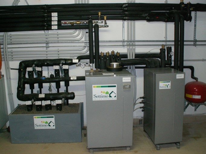
© Copyright:
Copying with reference to “IEA EBC Annex 54 Integration of Micro-Generation and Related Energy
Technologies in Buildings” permitted.
Technische Universität München, Germany 2014
All property rights, including copyright, are vested in Technische Universität München, Operating
Agent for EBC Annex 54, on behalf of the Contracting Parties of the International Energy Agency
Implementing Agreement for a Programme of Research and Development on Energy in Buildings and
Communities.

Disclaimer Notice: This publication has been compiled with reasonable skill and care. However,
neither Technische Universität München nor the EBC Contracting Parties (of the International Energy
Agency Implementing Agreement for a Programme of Research and Development on Energy in
Buildings and Communities) make any representation as to the adequacy or accuracy of the
information contained herein, or as to its suitability for any particular application, and accept no
responsibility or liability arising out of the use of this publication. The information contained herein
does not supersede the requirements given in any national codes, regulations or standards, and
should not be regarded as a substitute for the need to obtain specific professional advice for any
particular application.

Citation: Evgueniy Entchev, Peter Tzscheutschler. “Integration of Microgeneration and Related
Technologies in Building”, published by Technische Universität München, Germany, 10/2014
ISBN 978-3-00-047731-7

Participating countries in EBC:
Australia, Austria, Belgium, Canada, P.R. China, Czech Republic, Denmark, Finland, France, Germany,
Greece, Ireland, Italy, Japan, Republic of Korea, the Netherlands, New Zealand, Norway, Poland,
Portugal, Spain, Sweden, Switzerland, Turkey, United Kingdom and the United States of America.

This document may be downloaded from: www.iea-ebc.org

2
Integration of Microgeneration and
         Related Technologies in Building

             Final Report of Annex 54 of the
              International Energy Agency’s
    Energy in Buildings and Communities Programme

Authored by:
Evgueniy Entchev (National Resources Canada, Canada)
Peter Tzscheutschler (Technische Universität München ,Germany)
Ken Darcovich (National Research Council of Canada, Cnada)
Maurizio Sasso (Università degli Studi del Sannio, Italy)
Adam Hawkes (Imperial College London, UK)
Atsushi Akisawa (Tokyo University of Agriculture and Technology, Japan)
Giovanni Angrisani (Università degli Studi del Sannio, Italy)
Per Balslev (Dantherm Power, Denmark)
Ian Beausoleil-Morrison (Carleton University, Canada)
Caterina Brandoni (Università Politecnica delle Marche)
Nick Kelly (University of Strathclyde, UK)
Bruno Lee (Technische Universiteit Eindhoven, Netherlands)
Euy-Joon Lee (Korea Institute of Energy Research, Korea)
Marco Manzan (Università degli Studi di Trieste, Italy)
Hajo Ribberink (National Resources Canada, Canada)
Antonio Rosato (Seconda Università degli Studi di Napoli Italy)
Carlo Roselli (Università degli Studi del Sannio, Italy)
Tatsuo Sakonji (Tokyo Gas, Japan)
Sergio Sibilio (Seconda Università degli Studi di Napoli Italy)
Michael Steck (Enwida, Germany)
Juliana Zapata Riveros (Katholieke Universiteit Leuven, Netherlands)

                                                                          3
Acknowledgements
This report is the result of an international project performed within Annex 54 of the IEA/EBC
programme. We would like to express our great appreciation to the participants of Annex 54 for their
contribution as well as for the support given by different national bodies.
The guidance of the EBC Executive Committee is gratefully acknowledged.

Evgueniy Entchev, Peter Tzscheutschler (Operating Agents)

4
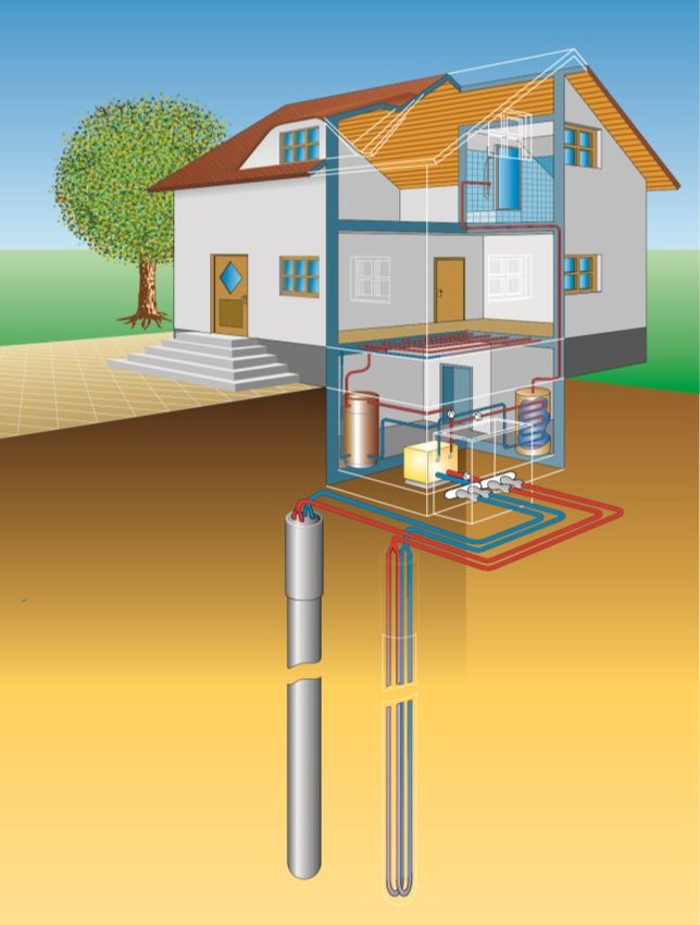
Table of Contents
Executive Summary .........................................................................................7
1    Introduction ..............................................................................................9
    1.1        Focus of Annex 54 ................................................................................................................................... 9
    1.2        Structure of Annex ................................................................................................................................ 10

2    Micro-Generation Technologies and Systems .......................................... 13
    2.1        Combined-Heat-and-Power (CHP) Systems .......................................................................................... 13
          2.1.1 Internal Combustion Engine ............................................................................................................ 13
          2.1.2 Stirling Engine .................................................................................................................................. 14
          2.1.3 Fuel Cell ........................................................................................................................................... 16
    2.2        Renewable Power and Poly Generation................................................................................................ 17
          2.2.1 Photovoltaic (PV) ............................................................................................................................. 17
          2.2.2 Heat Pumps ..................................................................................................................................... 19
          2.2.3 Batteries as Residential Electricity Storage ..................................................................................... 22
          2.2.4 Thermal Storage .............................................................................................................................. 23
          2.2.5 Chiller ............................................................................................................................................... 25

3    System Modelling and Demand Profiles .................................................. 27
    3.1        Demand Profiles .................................................................................................................................... 28
    3.2        Models for CHP units ............................................................................................................................ 30
          3.2.1 Calibration and Validation of AISIN SEIKI ICE micro-CHP unit ......................................................... 31
          3.2.2 PEM Fuel Cell Model Calibration Using Multiple Regression Method............................................. 32
    3.3        Models of System Components ............................................................................................................ 35
    3.4        Modelling of complete systems ............................................................................................................ 35
          3.4.1 System Model with Internal Combustion Engine implemented in TRNSYS..................................... 36
          3.4.2 System Model with Internal Combustion Engine implemented in Matlab/Simulink ...................... 39
    3.5        Optimization Tool Using a Unit Commitment Approach ...................................................................... 41

4    Performance Assessment ........................................................................ 45
    4.1        Methodology ......................................................................................................................................... 45
    4.2        Test Procedures..................................................................................................................................... 51
    4.3        Review on National Studies................................................................................................................... 53
          4.3.1 Country-Specific Simulations, Experimental and Field Test Studies based on CHP systems ........... 53
          4.3.2 Country Specific Simulations, Experimental and Field Test Studies based on CCHP systems ......... 60

                                                                                                                                                                       5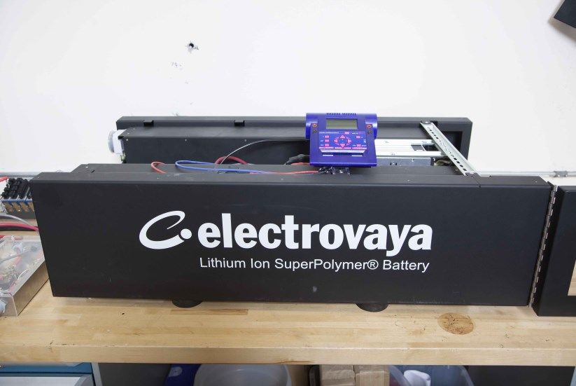
5    Drivers of Commercialization and Support Mechanisms .......................... 69
    5.1        Landscape of Support Mechanisms ...................................................................................................... 70
          5.1.1 Feed-In Tariffs for Microgeneration ................................................................................................ 70
          5.1.2 Grants .............................................................................................................................................. 73
          5.1.3 Building Regulations ........................................................................................................................ 74
          5.1.4 Regulation for Smarter Energy Systems .......................................................................................... 74
          5.1.5 Summary of Support Mechanisms .................................................................................................. 75
    5.2        Micro-generation Economics with Support Mechanisms ..................................................................... 76
          5.2.1 Economic Performance Assessment with Support Mechanisms .................................................... 76
          5.2.2 Economic Performance with Support Mechanisms ........................................................................ 76
          5.2.3 Advanced Performance Assessment with Support Mechanisms .................................................... 79

6    Summary, Conclusion and Outlook .......................................................... 81
    6.1        Summary ............................................................................................................................................... 81
    6.2        Conclusions ........................................................................................................................................... 82
    6.3        Outlook to Possible Future Work .......................................................................................................... 85

Abbreviations................................................................................................ 87
References .................................................................................................... 89
Image Sources ............................................................................................... 96
Background Information ............................................................................... 97

6
Executive Summary
Micro-generation is a novel method for producing heat and power on site and near the end-
user with high reliability, efficiency, and security of energy supply. The variety of micro-
generation technology choices and applications is strongly dependent on a building’s electric
and thermal load profiles. Building integration of micro-generation systems is challenging
because the loads are small and stochastic in nature, and the diversity is high. Given the
rapidly increasing numbers of micro-cogeneration installations around the world, there is a
pressing need for knowledge to enable informed choices to be made on where and when
the installation of micro-cogeneration systems is appropriate. To properly integrate these
systems in buildings, a significant number of operational and design issues must be
investigated and resolved.

This report contains the research findings of Annex 54 of the International Energy Agency’s
Energy in Building and Communities Programme (IEA EBC), which was established in 2009 to
further develop simulation models and performance assessment techniques affecting the
integration and future penetration of micro-generation systems in buildings. The Annex 54
research encompasses the broad range of end-uses of micro-generation and the systems
within it that might be deployed. The work reflects the state-of-the-art and future
performance in micro-generation, including integration with energy storage and demand-
side management technologies (e.g. responsive loads or dynamic demand control), virtual
utility, and smart energy networks. Finally, given the ubiquitous nature of this technology
and its broad societal impact, the research results are accessible to a broad audience
including engineers, policy makers, and businesses.

Annex 54 successfully developed models of micro-generation units and system components,
and implemented them into performance simulation platforms for state of the art buildings.
A huge amount of country-specific data has been collected from laboratory and field testing,
and has been used to determine demand-side profiles and to gain knowledge on micro-
generation system integration and performance under variety of real life operating
conditions.

The country-specific synthesis analysis performed by Annex 54 revealed generic
performance trends and “rules of thumb” for the appropriate deployment of micro-
generation technologies. The developed assessment methodology established common

                                                                                           7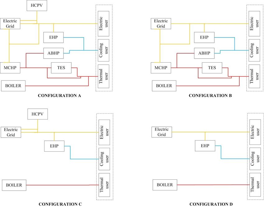
reference points for performance comparison, assessment methodology, and metrics, as
well as for the identification of generic not country-specific factors affecting the viability of
micro-generation systems and their appropriate deployment in buildings and communities.
A selection of the range of support mechanisms to incentivize the adoption of micro-
generation technology has been analysed. It is recognized that the supporting schemes can
change quickly and, as such, the country-specific incentives and grants have been examined
over the life time of the Annex. As such, the report provides a snapshot of feed-in tariffs,
grants, building regulations, and the role of micro-generation and associated technologies in
smarter energy systems.

8
1 Introduction
Annex 54 of the International Energy Agency’s Energy in Buildings and Communities Programme
(IEA/EBC) was established in 2009 to examine the “Integration of Microgeneration and Related
Technologies in Buildings”. The Annex was organized as a task-shared collaborative research project
involving 29 organizations from ten countries. The combined on-site generation of electricity,
heating, and cooling energy is an emerging technology with significant potential to deliver energy
efficiency, as well as environmental benefits, through reduced primary energy (PE) consumption and
lower greenhouse gas (GHG) emissions.

Background
The starting point of Annex 54 was the work performed within IEA/ECBCS Annex 42 [1-1]. This Annex
focused on the modelling of fuel cells and other micro-cogeneration systems. Some of the major
outcomes included: hot water and electrical load data for use in modelling studies; calibrated models
of fuel cell, internal combustion (IC) engine and Stirling engine (SE) devices; experimental protocols
for the testing of devices; and empirical validation datasets and country-specific performance studies
on residential micro-cogeneration systems.
Given the rapidly increasing number of micro-cogeneration installations around the world, there was
a pressing need to conduct further research to enable informed choices to be made on where and
when the installation of a micro-cogeneration system is appropriate. The research of the proposed
follow-on Annex 54 should encompass the broad range of end-uses for micro-generation, and the
systems within which it could be deployed. Furthermore, the work should properly reflect the state-
of-the-art and future performance in micro-generation, including integration with energy storage
and demand-side management technologies (e.g. responsive loads or dynamic demand control).
Finally, given the (potentially) ubiquitous nature of this technology and its broad societal impact, the
research results from the Annex should be accessible to a broad audience including engineers, policy
makers, and businesses.

1.1 Focus of Annex 54
The focus of Annex 54 has been shifted from model development and experimentation (Annex 42)
towards a more expansive analysis of micro-cogeneration and associated technologies. The scope of
activities encompasses multi-source micro-cogeneration systems, polygeneration systems, and
renewable hybrid systems and their integration in supply objects. Additionally, components as
energy storage systems and advanced control systems are included, as well as demand-side
management technologies.
Performance of integrated systems is analysed, as well as the wider effects of micro-generation on
low-voltage power distribution systems.

                                                                                                      9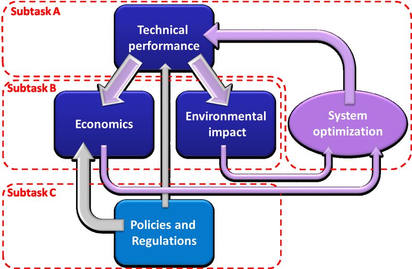
The work focuses mainly on the simulation of numerical models of integrated micro-generation
systems. The data were derived from laboratory experiments and field testing services to calibrate
models and derive load profiles. The results are performance studies into the efficiencies, economics,
and environmental impact, in terms of primary energy consumption and CO2-emissions, of micro-
generation technologies.
Additionally, diffusion strategies for the mass deployment of micro-generation-related technologies
are examined; this activity encompasses a regulatory and market review, along with data emerging
from the technical analysis.

1.2 Structure of Annex
To accomplish the aforementioned, the three subtasks have been defined to organize the work of
Annex 54, as illustrated in Fig. 1-1:

Subtask A: Technical Development
Subtask A undertakes the model development and data collection activities that underpin the work
of Subtasks B and C, with the emphasis on the optimized operation of micro-generation systems. This
requires the development of models of contemporary micro-generation devices and controllers to
maximize the energy performance for local, and possibly community, energy needs in different
operational scenarios.
This work also involves the specification of boundary conditions for the modelling of micro-
generation, especially the establishment of appropriate hot water and electrical demand profiles.

Subtask B: Performance Assessment
Subtask B uses simulation as a means to develop an extensive library of performance studies
covering different technology types and combinations, including the performance in different
countries and with different end-users. The simulation work initially focusses on
improving/optimizing the performance of basic but realistic micro-generation system configurations
in a limited set of operational contexts. Subsequent work features a wider range of system
components (such as electrical storage technologies), system functions, and end-users.
A synthesis analysis is undertaken with a view to identifying generic performance trends and “rules
of thumb” regarding the appropriate deployment of micro-generation technologies. This requires the
establishment of common reference points for the comparison of performance, requiring agreement
on a common assessment methodology and metrics, and the identification of generic demand and
supply technology characteristics.
The Subtask will focus on the applications of micro-generation in individual residences, multi-
residences, and small commercial buildings. However, the scope of the work also encompasses
mobile energy systems such as Plug-in Hybrid Electric Vehicles (PHEV) and more conventional EVs, as
well as demand-side management through other appliances.

10
Subtask C: Technically Robust Mechanisms for Diffusion
Micro-generation is an emerging class of technologies, and, as such, is only partially or poorly
understood in terms of market introduction. For example, early models of micro-generation support
in the residential sector are closely tied with energy efficiency; however, important technical and
economic tensions/synergies exist between these interventions. Given interactions such as these,
there is a risk that commercialization and support strategies devised by decision makers will lead to
underperforming installations. To reduce this risk, decision makers require unbiased information
regarding the interaction between the technical performance of micro-generation and the
mechanisms for the diffusion of these systems.
Given the importance attributed to micro-generation in meeting many countries’ climate change
targets (i.e. requiring substantial penetration), Subtask C will draw upon micro-scale technical
analysis to assess the ability of micro-generation to enter the market, and to deliver on national and
international energy policy objectives.
The Subtask begins with an analysis of the technical implications of current regulatory approaches
supporting the deployment of micro-generation in OECD countries. Following on from this, case
studies of micro-generation commercialization in a variety of OECD countries are developed, drawing
on performance assessments emerging from Subtask B. The aforementioned tasks are undertaken
with a view to identify the key characteristics of the interactions between technical performance,
economic instruments, and commercialization strategies for micro-generation.

                                    Figure 1-1: Structure of Annex 54.

                                                                                                   11
12
2 Micro-Generation Technologies and Systems
This chapter delivers a short overview of the micro-generation equipment, also including a balance of
plant components, investigated during Annex 54.

2.1 Combined-Heat-and-Power (CHP) Systems

2.1.1 Internal Combustion Engine
The internal combustion engine (ICE), well known from car engines, is presently the most mature
technology available for micro-CHP applications on the market because it achieves high thermal
efficiency, reduction of noise and vibrations, low maintenance and long life service, while requiring a
small installation space.

More specifically, these engines occupy small installation spaces, have high mechanical (25–35%) and
thermal (50–65%) efficiencies, produce low noise (
an overall energy efficiency of 85%. In the period 2003–2009, approximately 86,000 units were sold
in Japan. A new model was introduced to the North American market in 2006 that is capable of
supplying 1.2 kW of electric power.
In February 2002, Tokyo Gas and Aisin (Toyota group) [2-4] launched an MCHP system in Japan that
has also been available on the European market since 2006; the model is presented in Fig. 2-2. The
model, based on a 3-cylinder, 952-cm3 ICE, provides an electric output of 6 kW and 11.7 kW of
thermal power, with a total efficiency, at full load, equal to 85%.
The German manufacturer [2-5] Senertec., which has presently installed more than 32,000 units in
Europe, produces a cogeneration unit with 5.5-kW electric and 12.5-kW thermal power output called
Dachs, illustrated in Fig. 2-3. This unit is based on a one-cylinder four-stroke ICE that has a
displacement of 579 cm3 and can be fuelled by natural gas, LPG, fuel oil, or biodiesel. The total
efficiency at full load is approximately 90%.
Vaillant, with the Ecopower 4.7 module [2-6], produces an MCHP system, based on a Briggs &
Stratton 5HP engine, which is fuelled by natural gas or propane. The MCHP system produces 4.7-kW
electrical and 12.5-kW thermal outputs for an overall energy efficiency of up to 92%. The
cogenerator can modulate the electric power between 2.0 and 4.7 kWel, the range of the
corresponding thermal power is 6.0 to 12.5 kWth.
Within the power range of 4 kWel onwards, other manufacturers offer systems with comparable
technical characteristics to the systems described above.

                                       Figure 2-3: Senertec MCHP

2.1.2 Stirling Engine
The Stirling engine was invented by Robert Stirling in 1817. It operates through the cyclic expansion
and compression of a gas caused by heating and cooling. Mechanical power is captured through the
movement of a piston in a cylinder, comparable to other reciprocating engines. One advantage of the
process is that, owing to the external combustion outside the cylinder, solid fuels such as wood can
also be used as fuel.
In modern micro-CHP units, a fuel is used to heat the process (expansion of the gas). The heat
recovered from the cooling site (compression of the gas) can then be used to supply heat to a
building.

14
Aside from prototypes, some developments have been made in pilot manufacturing and wider
applications in field tests:
Solo Stirling (7.5 kWel, 22 kWth, operated with natural gas)
Sunmachine (3.0 kWel, 10.5 kWth, operated with wooden pellets)
WhisperGen (1.0 kWel, 7.5 kWth, operated with natural gas)
Microgen Stirling (1.0 kWel, 6.0 kWth, operated with natural gas)
However, at present only one system, the SE produced by the Microgen Engine Corporation, is
manufactured in larger quantities and is available on the market. This system is not sold directly to
the final consumer but several European manufacturers of heating appliances have integrated this SE
into their heating appliances, usually in combination with a condensing boiler.
Measurements made with the Solo systems demonstrated an electrical efficiency of approximately
25%. However, micro-CHP systems based on the Microgen SE have achieved electrical efficiencies of
only 12–15%. In both cases, the overall efficiency, including the use of heat, is in the range of 90 to
94%.
Fig. 2-4 and 2-5 show two Stirling micro-CHP systems. Both contain a condensing boiler to service
peaks in the heat demand and a control system. The left engine, produced by Senertec, also
comprises a 530 l thermal storage.
Figure 2-4: Stirling micro-CHP system Figure 2-5: Stirling micro-CHP system
Senertec Dachs Stirling Remeha eVita 28c
152.1.3 Fuel Cell
Fuel cells offer the possibility of converting a fuel, usually hydrogen, directly into electricity by a
catalytic electrochemical reaction. Heat is a by-product of this process that also can be used.
Two types of fuel cells have been proven to be suitable for cogeneration purposes:
Proton Exchange Membrane Fuel Cells (PEMFC):
This type of fuel cell uses pure hydrogen and oxygen from the air to generate electricity and
heat using a polymer membrane, at temperature level of up to approximately 85°C, with
electrical efficiency of approximately 35%. To convert natural gas into hydrogen, a reforming
and purification process has to be implemented ahead of the fuel cell.
Solid Oxide Fuel Cells (SOFC):
SOFC usually utilize a ceramic material as electrolyte and are operated at temperatures
typically above 650°C. This high temperature level can be used to develop an internal
reforming of fuels, with hydrogen content in the form of natural gas. The electrical efficiency
is in the range of approximately 50%.
This technology has reached the highest maturity in Japan. A fuel cell household cogeneration
system, powered by natural gas and liquefied petroleum gas, was released in 2009 and has been sold
under the Ene-Farm brand [2-7] to a total of 50,000 houses.
The Ene-Farm system generates power on-site to be used within the households; the resultant heat
is effectively utilized for the domestic supply of hot water. Consequently, the energy utilization rate
is approximately 86%. A learning function records the daily patterns of electricity and hot water use
in the household; this allows the system to estimate and determine the best operation plan of when
to start/stop the generation for maximum energy efficiency. In comparison with conventional power
generation systems, the Ene-Farm system cuts primary energy consumption by approximately 37%,
and CO2 emissions are reduced by approximately 49%.
CALLUX is a field test being performed in Germany since 2008, with the goal of installing 500 fuel cell
CHP systems in residential buildings. The target issues are to gain experience in operating fuel cell
systems, increasing system reliability, and reducing maintenance costs. One particular focus is on
data handling and communication with the fuel cell system. Consequently, the Callux-Box was
developed, allowing a scheduled operation of the fuel cell systems [2-8].
A comparable project, conducted at the European level, is Ene.Field, which started in 2012, bringing
together more than 50 partners from 12 countries. The aim is to install 1000 fuel-cell CHP units to
stimulate cost reductions by transitioning to serial production. Policy mechanisms related to
domestic micro-CHP will be analysed and commented on, and business models will be investigated.
[2-9]
16Figure 2-6: Panasonic Fuel Cell MCHP
2.2 Renewable Power and Poly Generation
2.2.1 Photovoltaic (PV)
Solar energy is presently the most abundant, inexhaustible, and cleanest of all the renewable energy
resources. The power from sun, intercepted by the earth, is approximately 1.8 x 10¹¹ MW, which is
many times larger than the present rate of all energy consumption. A photovoltaic (PV) system is a
device that converts solar energy into electricity directly, without any heat engine to interfere.
Typical applications of PV systems in use today are for power sources, water pumping, for use in
remote buildings, solar home systems, communications, satellites, and many more; the demand for
PV systems is increasing every year. An example of PV application in a building is presented in Fig. 2-
7.
PV modules have achieved mass production, with some 40 GW annual production capacity. A typical
module has a peak power of 250 W with an efficiency of up to 19%. PV installations are counted in
the millions and some installations have already reached capacities of more than 100 MWp, with
capacities of 500 MWp being projected.
17Figure 2-7: Building Integrated Photovoltaic System in Canada by Schletter and SkyFire with “turtle” roof shape [2-10]
PV applications can be classified into on-grid and off-grid applications:
1. On-Grid Applications:
The PV system feeds surplus electrical energy directly into the electricity supply grid. The
benefits of this on-grid connected PV power generation are generally evaluated based on its
potential to reduce costs for energy production and generator capacity, as well as its
environmental benefits.
2. Off-Grid Applications
Currently, PV systems are most competitive at isolated sites, away from the electric grid that
require relatively small amounts of power, typically less than 10kWp. In these off-grid
applications, PV systems are frequently used in the charging of batteries, thus storing the
electrical energy produced by the modules and providing the user with electrical energy on
demand.
Concentrating Photovoltaic (CPV) Systems
Most of photovoltaic panels are made of Si in mono-crystalline, poly-crystalline, or amorphous forms.
Chemical composite materials (Ga, As, In) are used for very highly efficient solar cells. In order to
achieve these high efficiencies of approximately 40%, multi-junction cell technology is employed [2-
11]. Multi-junction cells consist of three or more layers of very thin solar cells, each of which absorbs
solar irradiation at a different wave range.
Generally, multi-junction cells are installed in concentrating photovoltaic (CPV) systems, which have
primary optics such as lenses or mirrors to concentrate solar irradiance onto the cells. Owing to
multi-junction cells being very expensive to produce because of the advanced technology involved, it
is advantageous that this concentration results in a reduction in the cell size. There are several types
of lenses used in this concentration. Flat Fresnel lenses are used commonly in CPV systems. 3D-
shaped lenses, for example dome shaped Fresnel lenses with the concentration ratio of 500 suns,
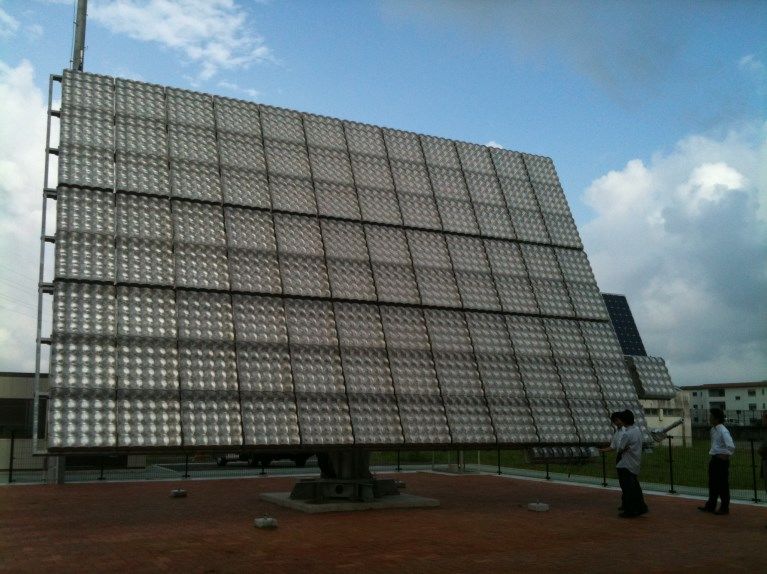
18were developed for CPV modules in Japan. CPV modules have to be mounted on sun tracking devices
with two axes in order to capture solar incident in a normal direction (Fig. 2-8). While flat PV modules
can intake not only direct incident but also diffused radiation from the sun, CPV modules can only
utilise direct incident radiation. Consequently, it can be said that CPV modules are suitable for areas
with rich direct solar radiation. For example, CPV systems are already employed to supply electricity
on a commercial basis in Arizona in the US.
Figure 2-8: CPV with dome shaped lenses
Hybrid Solar Panels
Hybrid solar panels are designed for recovering thermal energy as well as producing electricity using
one module. The efficiency of commonly used PV cells is approximately 10–15%, which implies that
the rest of solar energy turns into heat. Hybrid solar panels work by collecting such heat to supply
domestic hot water. Generally, these panels have a layered structure where PV cells are fixed on a
metal plate to integrate the extraction of electricity and thermal energy from the same component.
The heat generated in the cells is transferred to fluid flowing just behind the metal plate to produce
hot water.
It is advantageous that one device can generate different types of energy at the same time, like co-
generation. Considering that roof areas are a form of restricted resource in urban areas, it is
attractive for hybrid solar panels to share solar collecting areas for both PV and solar water heating.
Another beneficial point is that the heat recovery from the cells results in decreasing the
temperature of the cells and, therefore, improves the efficiency of electricity generation. This
technological development is currently ongoing.
2.2.2 Heat Pumps
Heat pumps (HPs) are widespread devices that are able to extract heat from a low-temperature
source, making it available on a higher temperature level. The process is performed at the expense of
19mechanical or thermal energy. Different classifications are possible by taking into account different
features:
type of energy source (mechanical, electrical, thermal)
low-temperature source (air, water, ground, waste heat)
kind of service (heating, domestic hot water (DHW), combined)
type of fluid (air, or water)
An electrically driven compression HP, the best known system, employs an inverse vapour
compression cycle; this extracts thermal energy from the low temperature source by evaporating a
fluid. Following this, the vapour is compressed and releases the absorbed heat in a condenser.
Afterwards, the condensed liquid is expanded in a valve to restart the cycle.
The efficiency of an electrically driven HP is given by the Coefficient of Performance (COP) and
represents the ratio between the energy released to the high temperature source and the energy
absorbed by the compressor. Depending on the temperature of the heat source and the heat supply,
the COP is typically in the range of 3 to 5. As a HP consumes electricity, the effort required to
generate the electricity has to be taken into account.
Absorption heat pumps (AHPs) use thermal energy to drive the process. The refrigerant is absorbed
by an absorbing fluid; this forms a liquid solution. Heat provided to the generator separates the
refrigerant, which evaporates and follows the same pattern of the vapour compression cycle, with
condensation, expansion, and evaporation; however, instead of entering a condenser, the refrigerant
is mixed with the absorbing fluid to start the process again. For HPs, the usual combination of
refrigerant and absorbing fluid is ammonia and water, or water and lithium bromide.
Presently, AHPs are best suited to heating large buildings because heating capacity reaches a
minimum of approximately 35 kW, which is usually higher than the capacity required for single
dwelling. The COP for a gas driven AHPs is in the range of 1.5 to 2.0.
Common heat sources used are the external air and the ground:
Air source heat pumps (ASHPs) extract thermal energy directly from external air and transfer
it to internal ambient air (air-to-air HPs) or to a secondary fluid such as water (air-to-water
HPs). The benefits of this arrangement are the low cost and easy installation, while the main
drawback is the reduction of COP with low external temperatures, an additional problem
occurs with frost formation occurring on the condenser.
Ground source heat pumps (GSHPs) use the ground as a source, which is at a rather constant
temperature. Therefore, the capacity of these systems is nearly constant and independent
from the external air temperature. Additionally, the COP of a GSHP is constant and usually
higher than that of the ASHP at low external temperatures. Heat can be extracted from the
ground using horizontal or vertical tubes; Fig. 2-9 illustrates a possible solution for HP
installation for heating and DHW production. The requirement of excavation or drilling for
GSHPs represents the main drawback of the system, bringing a high initial cost.
20Figure 2-9: GSHP with vertical boreholes for heating and DHW
HPs can be used for cooling purposes, too. The COP of GSHPs is higher than when using ASHPs. If the
ground temperature is sufficiently low, the HP can be switched off, performing a free cooling of the
conditioned spaces. Fig. 2-10 presents a GSHP with a free cooling unit
Figure 2-10: A GSHP, centre, left connections with two boreholes with two tubes each, right the free cooling unit
212.2.3 Batteries as Residential Electricity Storage
Battery energy storage (BES) is becoming relevant at the residential level when transient renewables
are employed or with thermally led cogeneration systems that have a significant night time heat
demand. A battery system for a single family home would typically include a battery pack with a
capacity in the range of 4 to 8 kWh, capable of delivering up to 5 kW of power. In order to connect
this battery to the household electrical system, as well as the external power grid, a DC to AC
electrical inverter is required, along with a battery-management system in order to ensure safe and
sustainable function of the battery pack. At present, there are a number of suitable battery types
available, including the long-established and conventional lead-acid systems, batteries based on
nickel-cadmium, nickel metal hydride, lithium ion, lithium polymer, sodium sulphur, vanadium redox,
zinc bromine, or metal air compositions [2-12].
Depending on battery chemistry, the capital cost for equipment can range from $65 to $1560 per
kWh, with roundtrip electrical efficiencies from 50 to approximately 95%, and service lifetimes
ranging from only a few hundred cycles up to 10,000 cycles [2-12]. The characteristics of lithium ion
batteries that make them highly suitable for electrical storage include very high energy density, good
power output, good cycle life with a broad cycling range, high coulombic efficiencies, and
comparatively low heat output [2-13]. For prolonged intensive use, such as a in a micro-cogeneration
system, proper control and management of a lithium ion battery is crucial to ensure high capacity
retention and safe operation. Lithium ion batteries at ratings of approximately 2 kW/6 kWh are of a
size suitable for development for residential power supply and storage. It has been demonstrated
that they can provide the consumer with economic benefit in a residential micro-generation context,
as storing energy can reduce peak power demands. Benefits also apply to power utilities through
offsetting costly infrastructure upgrades to the power grid [2-14]. Such a system, as illustrated in Fig.
2-11, was built with an integrated inverter and management electronics, at a prototype cost of
approximately $10,000.
Figure 2-11: Residential storage battery built by the Canadian manufacturer Electrovaya
22High capital costs of residential batteries continue to be a concern. Studies have revealed that time
shifting of grid power with batteries in time-of-use pricing environments is not a strategy that
justifies the large capital expense [2-15]. Peak shaving can occur through widespread use of large
residential batteries, but such a scenario would need to be led through the efforts of a coordinating
utility, and has yet to be demonstrated. However, at present, some large-scale commercial BES
systems have been built and installed [2-16]. At the current adoptive stage, progress towards
economy of scale with batteries is occurring. The battery management electronics for smaller storage
systems contribute to their current high cost, thus larger BES systems are more economically viable.
Very recent initiatives, notably in Japan in response to the Fukushima crisis, are making residential
batteries more of a commercial reality. Examples include the Honda Smart Home System [2-17],
undergoing field trials in Saitama, which consists of CIGS thin-film solar panels, a home battery unit, a
household gas-engine cogeneration unit, a hot water supply system, and control electronics. In
November 2012, Toshiba [2-18] launched 6.6-kWh/3.0-kW “eneGoon” rapid-charge Li-ion residential
batteries, claiming a 6000-cycle lifetime. US-based Power-One inverters and Japan’s Panasonic
lithium ion batteries will be integrated into energy storage systems for the residential, commercial,
and utility-scale, and grid-connected energy storage markets in 2013 [2-19]. Similarly, in summer
2013, Nichicon Corporation introduced an energy management system that combines a solar power
generating system from partner Kyocera, with their long-lasting, high-capacity lithium-ion battery
storage units [2-20]. Regulatory assistance in Germany to cover 30% of battery capital costs, in
recognition of the value of combining residential battery storage to residential PV systems, was made
available in late 2012 [2-21]. Related to this, it was reported that a 5.3-kW solar PV system could
provide enough power for 24 hours of household demand, and a 10.6-kWh battery capacity would be
suitable to discharge surplus power for use at night [2-22].
2.2.4 Thermal Storage
Thermal storage is a key component for thermal plants, which can be used in heating and cooling
applications. The main purpose of thermal storage is to resolve the problem of the shift between
energy demand and production, a typical problem encountered if renewable sources are used for
energy production. Thermal energy storage can be of sensible or latent type, and various storage
materials are employed. In heating plants, the dominant storage material used is water. The amount
of energy that can be stored depends on the volume of the tank and the temperature difference
between the outlet and return temperatures. Latent thermal storage using phase change materials
(PCMs) can also be used to enhance the amount of stored energy. For cooling applications, ice
storage is utilised, where ice slurry and ice-on-coil are the solutions employed.
Sensible storage systems
The typical storage medium in heating and cooling plants is water owing to its common availability,
low cost, and the high specific heat content. A vertical cylinder tank is the most common solution
adopted. Internal coils connected to thermal energy sources, such as boilers, cogenerator systems, or
solar collectors can be used to heat the water in the tank. The number of heating coils usually varies
between one and three. One may be used to charge the storage from a micro-CHP system, the
23second coil can is used to integrate solar heat, while the third heat coil is used to heat domestic hot
water.
Thermal storage in domestic plants is typically used for domestic hot water supplies. The stored
water guarantees continuity of water service at a constant temperature. Thermal storage is also
required in conjunction with solar collectors for collecting energy during sunny hours and to have hot
water available when it is required. Fig. 2-12 represents a tank with two coils, the lower is usually
connected to the solar collector, while the upper is connected to a boiler for backup heating.
Multiple heat generators can be available so the tank can have additional coils; for example, the tank
can be connected to a solar collector, and a wood boiler or a cogenerator.
Collector
Boiler
M
heating
system
DHW
Figure 2-12: A tank with two heat exchangers for Solar Domestic Hot Water Systems
Fig. 2-13 represents a tank-in-tank solution combining domestic hot water storage (inner tank) with a
thermal storage for the heating system (outer tank). With this solution, a unique heat generator can
provide energy to both the heating system and the domestic hot water system.
Boiler Collector
DHW
Heating
System
Figure 2-13: Tank in Tank plant for Solar Domestic Hot Water System
24Latent storage systems
Heat storage can be enhanced by means of substances undergoing a phase change during charge and
discharge of the storage, usually from the solid to liquid phase. Consequently, the energy is stored as
latent heat. The important parameters in such circumstances are the latent heat content of the
material and the phase change temperature. Different materials based on paraffin or salt hydrates
are available commercially, with phase change temperatures in the range 30 to 64°C [2-23]. Different
approaches have been used to integrate PCMs into thermal storage. Typical methods are PCMs
packed in cylinders or their inclusion in spherical containers.
2.2.5 Chiller
Absorption and adsorption chillers
Absorption chillers (Fig. 2-14) represent the most common thermally activated technology applied in
existing Combined Cooling, Heating and Power (CCHP) systems (hotels, hospitals, commercial
buildings, etc.) [2-24].
Typical absorption chiller installations, with a cooling capacity of 10 to 15 kW producing chilled water
at a temperature level of 15 to 18°C, are operated using thermal power at a temperature level of 75
to 90°C, with an COP of approximately 0.65 to 0.78 [2-25,2-26]. Lithium bromide/water and
water/ammonia are the working pairs that are typically used in these systems.
Adsorption cooling is a novel technology that incorporates low-grade heat sources [2-24]; however,
this technology has the problems of low COP (0.3–0.5), low cooling power per volume, and significant
weight. Few systems with a cooling power of 10 to 100 kW are available on the Chinese and
American markets, and they have a high investment cost (600 €/kW of cooling power installed). In
terms of small machines, two new companies are offering novel products: SorTech AG from Germany
offers a 8-kW and 15-kW water-silica gel chiller (Fig. 2-13) and Invensor GmbH, also from Germany,
offers a 7 kW and a 10 kW water-zeolite chiller.
(a) (b)
Figure 2-14: a) absorption chillers; b) Sortech eCoo
25Desiccant wheel
A desiccant wheel (DW) (Fig. 2-15) is a rotor filled with a solid desiccant material, which rotates
slowly between the process air, to be dehumidified, and the regeneration air. It can be regenerated
by heat from a gas-fired boiler or an electric resistance. However, the energy saving and the
reduction of the environmental impact that these systems can achieve are higher when the desiccant
material is regenerated by means of “free” thermal energy, for example from cogenerators or solar
collectors. In these cases, a desiccant material that can be effectively regenerated with low-
temperature thermal energy is obviously needed, [2-27].
Desiccant materials that have been applied include silica gel, lithium chloride, or a molecular sieve.
The process of regeneration occurs in the range 50:50 to 75:25.
Figure 2-15: The desiccant wheel
Commercial applications of hybrid systems include schools, auditoriums, hospitals, office buildings,
supermarkets, and restaurants, among others. However, thanks to its energy and environmental
benefits, the use of desiccant technology is also spreading to tertiary and residential buildings.
263 System Modelling and Demand Profiles
Annex 54 activities on gathering load profile data, and modelling efforts on micro-generation
equipment and systems are presented in this chapter. This work represents the main technical basis
for the performance assessment work also performed in this Annex.
For all environment energy simulations constructed, it is understood that the basis and validity of any
study hinges on the load profile data used as the energy demand input. Recently, micro-generation
has witnessed a shift in focus towards system design, integration, and optimization, as the
technology and the expertise linked to their implementation has matured. These changes have given
rise to gaps in the suitability of existing load profile data as inputs for energy-use simulations. New
understanding about system operations has demonstrated the stochastic nature of energy use, and
consequently, higher resolution temporal load profile data that properly reflect this are required.
These concerns were addressed in the Annex 54 activities on electric and hot water demand profiles
that are reported in this chapter.
As Annex 54 has broadened the scope of the equipment and system configurations under
consideration, so too have efforts in gathering load profile data broadened in recent years. A variety
of building types, some with specialized activities have been studied. As part of the commitment of
Annex 54 to contribute to the existing repository of load profile data, new member nations not
present during Annex 42 were requested to provide load profile data. The present Annex includes
these new load profile data from the new member nations, Japan and South Korea.
Modelling and simulation resides at the heart of the technical analysis performed in Annex 54. The
set of established prime movers for micro-CHP systems has not significantly changed in the past few
years. Consequently, the updated focus of the present Annex is directed more at auxiliary system
components for cooling, humidity control and/or energy storage, and the focus is aimed at more
optimal system efficiency, as well as performing investigations into system configurations and control
schemes, with a view to overall energy-use savings.
This chapter presents an overview of the research on residential cogeneration systems conducted
within Annex 54, reflecting an expanded scope that considered a diverse number of energy-use
system configurations; these were conceived and optimized in view of regional climatic factors, local
energy contexts, as well as associated impinging policy environments. Considerable attention has
been given to energy storage; this is because optimizing efficiency with either a thermally led or
electrically led system naturally leads to situations where the temporal load necessitates the
generation of excess heat or electricity, which must be managed. As such, the interplay and
compatibility of devices has become an important research topic. It has also become evident that the
scale of the CHP system is critical in determining its economic viability; consequently, considering
only single-residence applications may restrict the benefits of a broader implementation of micro-
cogeneration. In addressing questions of scale, a number of systems are considered on the
community or shared level, and the logistics and control of such systems have been examined in
Annex 54.
27In order to conduct performance assessment studies, the necessary inventory has to be developed.
Numerical models of micro-generation equipment and whole systems have to be developed and
implemented using suitable simulation tools, such as ESPr, TRNSYS or Matlab/Simulink. Demand-
profile data have to be investigated for later simulations. Laboratory experiments have to be
performed for model calibration and validation purposes (Fig. 3-1).
Figure 3-1: Context of data and models.
3.1 Demand Profiles
Typical reference energy-demand data for simulation purposes are needed for evaluating and
comparing the performance of micro-generation equipment and systems.
As presented in Tab. 3-1, several load profiles for electrical, thermal, and cooling demands of
different end-users and geographical areas have been provided by Annex participants. From field
measurements, data with a sampling rate of up to one second could be collected. However, in most
cases, data with time resolution of one or ten minutes are more common.
There were two approaches followed for defining energy-demand profiles:
Experimental, using data measured from field tests and laboratory experiments
Theoretical, using validated models of user behaviour and equipment data
Canadian, Japanese, South Korean, and German participants mainly followed an experimental
approach.
28Table 3-1: Overview of load profiles provided by the Annex 54 participants
Geographical area Electrical Hea- DHW Coo- Sector Note
ting ling
1-minute resolution; yearly
Ottawa, Canada X Residential demand; 12 buildings
analysed [3-1]
1-second time resolution; i)
Residential
Bavaria, Germany X X X four single families, ii) a
Service
health club, and iii) a hotel
1-hour resolution; i) a public
Bavaria, Germany X Service bath, ii) a hospital, iii) a
hotel, and iv) a greenhouse
Electrical load with 1-minute
resolution, thermal loads
26 areas in Japan X X Residential with 10-minute resolution;
yearly data measured
between 2002 and 2004
10-minute resolution; six
family apartments, 200 day
Osaka, Japan X X Residential
periods, taken from June
2007 through January 2009
1-second resolution; 50-unit
Nagoya, Japan X X Residential
block of bachelor flats
10-minute resolution; data
Kumagaya, comprise PV, micro-CHP,
X X X X Service
Yokohama, Japan and solar thermal
generation
Two models for generating
high-resolution electricity-
UK X Residential
demand profiles, based on
experimental data
Two measurement
Daejeon, Korea X X Residential campaigns: i) one residential
building, ii) ten apartments
Incheon, Korea X X Service 1,140-m2 office building
Profiles derived by
databases of Loughborough
Italy X X Residential
university and IEA-Annex 26
[3-2, 3-3]
Different types of dwelling
(Economy, Luxury,
Rome, Italy X Residential Standard) and number of
occupants (single/couple
and family)
4 years of measurement
Rome, Italy X Service
campaigns; office buildings
29Carleton University gathered occupant electricity-consumption data from 12 houses in Ottawa,
Canada. Analysing these data led to the following conclusions:
Occupant tendencies are a strong determining factor for the annual non-HVAC consumption
of a building,
Occupant electricity-consumption profiles vary significantly between buildings.
Japanese Annex members collected several energy-demand profiles of residential and service
buildings. Electricity-demand profiles were gathered for 26 different locations in Japan, thanks to
measurement campaigns conducted between 2002–2004. More recent campaigns also encompass
data of electricity and domestic hot water demand [3-4].
South Korea provided both heating- and cooling-demand data for residential and office buildings
located in two different areas, which were also used to define the total demand required to
characterize load-sharing applications.
German participants collected electricity- and heat-demand data of different residential and service
buildings. It is worthy of note that a one-second acquisition frequency can capture the dynamic
behaviour of the implemented energy systems.
The main difficulty in defining reference profiles lies in the high number of cases that need to be
studied in order to make the profiles statistically consistent. Nevertheless, some general information
could be derived from the experimental campaigns. Analyses of data from Italy show that buildings
characterised by a similar specific electrical load (defined in kW/m2) demonstrate a very similar
average seasonal load profile [3-5].
On the model-based generation of energy-demand data, two different approaches for generating
high-resolution residential electricity-demand data, have been presented by UK participants. A first
predictive energy-demand model for domestic electricity consumption was developed to define a
one-minute resolution synthetic electricity demand [3-6], while a second model was developed for
creating high-resolution electricity-demand data reflecting the effects of applying energy-efficiency
improvements in future years [3-7].
Italian participants applied the model mentioned above, starting from the electrical demand of
dwellings characterised by a different number of occupants (i.e. single/couple and family) and
building typology, to generate single and aggregated electricity-demand profiles [3-8].
3.2 Models for CHP units
The IEA/ECBCS Annex 42 developed two simulation models for accurately determining the thermal
and electric performance of residential cogeneration devices [3-9]; the first model was determined
for fuel-cell-based cogeneration units (SOFC and PEMFC), while the second was derived for
combustion-based systems (SE and ICE). Both models have been implemented within a variety of
whole-building modelling platforms.
The Annex 42 models rely extensively on parametric equations describing the relationships between
key input and output parameters; each of these parametric equations requires empirical constants
that characterize aspects of the performance of specific cogeneration devices. The establishment of
30You can also read