SI Scientific Instruments GmbH ... the better technology - PDUS210 210 Watt Ultrasonic Driver
←
→
Page content transcription
If your browser does not render page correctly, please read the page content below
SI Scientific Instruments GmbH ... the better technology
 Roemerstr. 67 | 82205 Gilching/Germany | Phone: +49 8105 77940 | E-mail: info@si-gmbh.de | Web: www.si-gmbh.de

 PDUS210
 210 Watt Ultrasonic Driver

PDUS210 V4 1 Modified 6/02/2021

Contents
Safety Warnings............................................................................................................................... 3
Revision History ............................................................................................................................... 3
Quick Start Recommendations ........................................................................................................ 3
Delivery Contents (Standard) ........................................................................................................... 3
Overview .......................................................................................................................................... 4
Electrical Specifications ................................................................................................................... 5
Standard Output Voltage Ranges .................................................................................................... 5
Mechanical Specifications ................................................................................................................ 7
PDUS210-FLEX Specifications ........................................................................................................ 8
Introduction to Ultrasonic Transducers ............................................................................................ 8
PDUS210 Operation ...................................................................................................................... 10
Choosing the Voltage Range ......................................................................................................... 14
Front Panel .................................................................................................................................... 16
Rear Panel ..................................................................................................................................... 17
Overload Protection ....................................................................................................................... 18
Desktop Software........................................................................................................................... 19
PDUS210-FLEX Operation ............................................................................................................ 29
Handheld Controller ....................................................................................................................... 31
RS485 Interface ............................................................................................................................. 33
Warranty and Service .................................................................................................................... 34

 PDUS210 V4 2 Modified 6/02/2021
Safety Warnings High Voltage This product produces potentially lethal voltages up to 282 Vrms. Observe Low-Voltage (as per ANSI C84.1-1989) safety precautions, e.g. ● Use an observer trained in low-voltage rescue ● Do not operate with exposed conductors ● Use appropriate signage, etc. Revision History Date Manual Changes 6/02/2020 R8 Added recommended impedance range Added support for external transformers Minimum frequency changed to 6 kHz 31/10/2020 R7 Added frequency range specifications Added 175V version 15/01/2020 R6 Added notes to “Standard Output Voltage Ranges” Quick Start Recommendations Most users will need to read the following sections in detail to gain an understanding of transducer characteristics and the various operating modes. That is, read the following sections in order. If you already have expert knowledge of ultrasonic transducers and their different operating modes, go straight to the section on Desktop Software. Delivery Contents (Standard) PDUS210 Amplifier (in chosen configuration) Handheld controller Handheld controller cable (DSUB9 3ft) 280W Desktop power supply IEC Power cable suited to the destination shipping address USB Cable (Type A) 3 Way plug-in screw terminals for output (Amphenol TJ0331530000G) 4 Way plug-in screw terminal for RS-485 connector (Amphenol TJ0431530000G) PDUS210 V4 3 Modified 6/02/2021

Overview
The PDUS210 is a complete solution for driving precision and high-power ultrasonic actuators.
Functions include high-speed resonance tracking of both series or parallel resonance modes,
vibration amplitude control, and analysis functions such as impedance and frequency response
measurement. The PDUS210 is well suited to both OEM product integration and laboratory use for
research and development. Applications include ultrasonic drilling and cutting, medical devices,
dental devices, ultrasonic testing, liquid cavitation, and vaporization.
The PDUS210 is controlled via USB and the included software package. An RS485 interface also
provides a straight-forward method to control and monitor the amplifier for automatic test and OEM
applications.
The PDUS210 generates a pure sine-wave output which avoids the excitation of secondary
resonance modes by the drive harmonics. This makes it ideal for operating at the electrical parallel
resonance, or ‘anti-resonance’. This operating point is close to the mechanical resonance
frequency but is less sensitive to changes in load dissipation, which is useful in precision
machining applications where constant vibration amplitude is desired.
The PDUS210 is available with standard output voltage ranges from 17 Vrms to 282 Vrms, and
current ranges from 0.7 Arms to 11 Arms. These ranges are optimized for load impedances
ranging from 1.5 Ohms to 400 Ohms at resonance. For research and development applications, a
reconfigurable version is available (PDUS210-FLEX), this version uses external output matching
transformers to allow operation at any of the available output voltage ranges.

 PDUS210 V4 4 Modified 6/02/2021

Electrical Specifications
 Specification Value Notes
 Output Voltage 0 – 800 Vp-p See standard voltage ranges
 Output Current Max 0 – 32 Ap-p See standard voltage ranges
 Load Impedance 1Ω – 5 kΩ See standard voltage ranges
 Output Waveform Sine wave
 DC Output Voltage Zero DC offset possible
 Output Isolation Isolated or grounded
 Max Output Power 210 W With optimal load impedance
 Internal Power Dissipation 130 W Maximum
 Frequency Range See table below 6kHz to 500kHz with modifications
 Power Supply 48 V, 280 Watt
 Phase tracking and 2ms frequency update rate
 Controller
 power control Resonance or anti-resonance
 Interface USB, RS485
 Digital IO 4 DIO For manual control

Standard Output Voltage Ranges
The following table lists the specifications of each model variant, including: the maximum output
voltage, the maximum output current, optimal load impedance and the recommended frequency
range.

 Voltage Voltage Amps Amps Optimal Load Range Frequency
 Order Code
 pk-pk RMS pk-pk RMS Load Ohms Ohms* kHz
 PDUS210-800 800 282 2 0.71 400 260 – 840 20 – 200
 PDUS210-600 600 212 2.6 0.92 225 146 – 472 20 – 200
 PDUS210-400 400 141 4 1.4 100 65 – 210 20 – 200
 PDUS210-200 200 70 8 2.8 25 16 – 52 20 – 200
 PDUS210-175 175 62 9.1 3.2 19.1 12 – 40 10 - 100
 PDUS210-100 100 35 16 5.7 6.25 4 – 13 20 – 200
 PDUS210-50 50 17 32 11.3 1.56 1-3 20 – 200

Note: The output voltage resolution and tolerance is 8 bits, or 256 levels. Therefore, the smallest
possible change in voltage is full-scale range / 256. The minimum output voltage is also limited by
resolution. When the amplifier is enabled and the output voltage is set to zero volts, the actual
output voltage may be up to 2% of the full-scale range.
* The load impedance range is the range of impedances which guarantee more than 100W of
power supplied to the load. Higher or lower impedances can be driven but with reduced power.

 PDUS210 V4 5 Modified 6/02/2021
The relationship between maximum achievable power and the load impedance is plotted in the
following figure. In this plot, the impedance is normalized by the optimal impedance; that is,

 =

For example, the optimal impedance of the PDUS210-400 is 100 Ohms, so with a 50 Ohm load,
the normalized impedance is 0.5, From the plot, it can observed that greater than 100 W can be
achieved with a normalized impedance from 0.65 to 2.1, which for the PDUS210-400, is 65 Ohms
to 210 Ohms.

 Figure 1. Maximum output power versus normalized impedance
The impedance ranges for other common power levels are listed in the following table. For
example, all amplifiers will supply more than 150W with a normalized load impedance between
0.71 and 1.4. For the PDUS210-400, this is equivalent to 71 Ohms and 140 Ohms.

 Minimum Power Lower Bound Upper Bound
 150W 0.71 × 1.4 ×
 100W 0.65 × 2.1 ×
 50W 0.53 × 4.2 ×

 Table 1. Minimum achievable power versus load impedance.

 PDUS210 V4 6 Modified 6/02/2021

Mechanical Specifications
Specification Value Notes
Enclosure Dimensions 227 x 168 x 54 mm LxWxH
Mass 1.4 kg
Temperature Range 0C - 50C
Humidity Non-condensing

 PDUS210 V4 7 Modified 6/02/2021
PDUS210-FLEX Specifications
The PDUS210-FLEX is identical to the standard PDUS210 except that it requires an external
transformer connected between the amplifier and transducer using the supplied cable. This allows
the user to switch between different output voltage ranges by changing the external transformer.
Please refer to the section PDUS210-FLEX Operation for instructions.
The PDUS210-FLEX must be purchased with at least one external transformer. The available part
numbers and specifications are:
Order Code Turns Voltage Voltage Amps Amps Optimal Load Range Frequency
 Ratio pk-pk RMS pk-pk RMS Load Ohms Ohms* kHz
TX210-800 18.18 800 282 2 0.71 400 260 – 840 20 – 200
TX210-600 13.64 600 212 2.6 0.92 225 146 – 472 20 – 200
TX210-400 9.09 400 141 4 1.4 100 65 – 210 20 – 200
TX210-200 4.55 200 70 8 2.8 25 16 – 52 20 – 200
TX210-175 3.98 175 62 9.1 3.2 19.1 12 – 40 10 - 100
TX210-100 2.27 100 35 16 5.7 6.25 4 – 13 20 – 200
TX210-50 1.14 50 17 32 11.3 1.56 1-3 20 – 200

 Table 2. External transformer specifications (only for the PDUS210-Flex)
A kit containing six transformers ranging from 17Vrms to 282Vrms is also available (TX210-Kit1).
This includes the following output voltage ranges: 17, 35, 70, 141, 212, and 282 Vrms.

 Figure 2. Output transformer (e.g. TX210-800)

 Specification Value Notes
 Input Connector Plug-in screw terminal Connecting cable supplied
 Output Connectors Identical to PDUS210 See “Front Panel” section
 Transformer Dimensions 104 x 57 x 51 mm LxWxH
 Mass 0.2 kg

 Table 3. External transformer mechanical specifications

 PDUS210 V4 8 Modified 6/02/2021

Introduction to Ultrasonic Transducers An introduction to the behaviour and operation of ultrasonic transducers can be viewed at the following link. Please familiarize yourself with these concepts before operating the PDUS210. https://www.piezodrive.com/ultrasonic-drivers/intro-ultrasonic/ The most important concept to understand is the relationship between the electrical and mechanical impedance response of a transducer. Figure 3 plots the mechanical and electrical frequency response of an ultrasonic transducer. The impedance minima at is known as the series resonance, which is approximately equal to the mechanical resonance frequency. At this frequency, the impedance phase response has a high positive slope and a value of approximately zero degrees. In this mode, the current is approximately proportional to the vibration amplitude, so current control is used to maintain constant vibration amplitude. If the mechanical load does not vary significantly, constant voltage amplitude is also appropriate. The impedance maxima at is known as the parallel resonance, which also has an electrical phase of approximately zero degrees but a high negative slope. In this mode, the voltage is approximately proportional to the vibration amplitude, so constant voltage results in approximately constant vibration amplitude regardless of mechanical load variations. Figure 3. Electrical and mechanical frequency response of an ultrasonic transducer PDUS210 V4 9 Modified 6/02/2021
PDUS210 Operation
Overview
The operating principle of the PDUS210 is summarized in Figure 4. The transducer is connected
on the right hand side to the output transformer. The transformer converts the internal +/-24V drive
voltage to the desired output voltage range, for example +/-200V. By default, the output
connection to the transducer is electrically isolated from ground but the negative output can also
be internally grounded using the jumper shown.
During operation, the voltage and current in the transducer is used to estimate the phase . The
measured phase is then used to control the frequency of the signal generator by comparing it to
the phase set point . The frequency controller stabilizes the feedback loop and controls the
settling time of the closed loop system. The feedback gain is normally determined experimentally
by slowly increasing the gain until the desired performance is reached or the response begins to
become unstable.
The signal generator has a variable amplitude and the frequency is normally controlled by the
phase control loop. It is connected to the power amplifier, which drives the output transformer and
transducer.

 Phase Frequency Signal Power
 Setpoint Controller Generator Amplifier Transformer
 Transformer
 Transformer Transducer

 Ground
 Connection
 Phase Detector
 Transformer
 Figure 4. Internal PDUS210 operation (in constant voltage, resonance tracking mode).

Resonance Tracking
The resonance tracking system of the PDUS210 is illustrated Figure 3. The phase detector (M)
measures the impedance phase angle between the primary voltage and current. The phase
controller ( ) varies the drive frequency to maintain a constant phase set point , which is
usually equal to zero.
To operate at a series resonance (impedance minima), the phase controller gain must be positive
to create a stable operating point.
To operate at a parallel resonance (impedance maxima), the phase controller gain must be
negative to create a stable operating point.

 PDUS210 V4 10 Modified 6/02/2021
Applications with high losses, i.e. low quality factor, may have a non-zero impedance phase angle
at resonance, e.g. 45 degrees. In such cases, an impedance response should be performed first,
to identify the desired operating phase that corresponds to the desired mechanical resonance.

 PDUS210 V4 11 Modified 6/02/2021
Control of Vibration Amplitude
Power ultrasonic applications can be categorized as either constant mechanical load, or variable
mechanical load. The requirements for both of these cases are described in the following.
Constant Mechanical Load
Constant load applications are the simplest case and include, for example, ultrasonic cleaners,
ultrasonic mixers, and any other application where the mechanical load does not vary significantly.
These applications can be operated with constant voltage at either the series or parallel
resonance.
Variable Mechanical Load
Applications with variable mechanical load include ultrasonic drills and cutters where the
mechanical load conditions are variable during operation. These applications generally require
some form of amplitude control in order to: 1) maintain vibration amplitude when the mechanical
load dissipation increases; and 2) to avoid vibration amplitude increasing when the mechanical
load dissipation is removed.
To achieve approximately constant vibration amplitude, a transducer can be driven with constant
voltage at the parallel resonance frequency, or constant current at the series resonance
frequency.
Constant voltage is the natural operating mode of the PDUS210 but constant current can also be
achieved by enabling the current tracking mode. The operation of current tracking mode is
illustrated in Figure 5. Current tracking mode has the same frequency control loop as Figure 4 but
it also has an additional feedback loop that varies the voltage to maintain a constant load current.
The current set point is and the controller is .
Current tracking mode is most useful for achieving constant vibration amplitude in transducers
operated at the series resonance mode (impedance minima).

 Phase Frequency Signal Power
 Setpoint Controller Generator Amplifier Transformer
 Transformer
 Transformer Transducer

 Ground
 Connection
 Phase and Current Detector Transformer

 Figure 5. Phase and current control loop in the PDUS210 driver.

 PDUS210 V4 12 Modified 6/02/2021
Power Control
When operating with constant voltage or current, a limit can be set on the maximum power
dissipation in the load. This power is the sum of dissipation in the mechanical load and the
transducer itself.
In some applications, such as welding, it may be preferable to control the dissipated power rather
than the vibration amplitude. The PDUS210 has a power control function that varies the voltage to
maintain a constant power dissipation in the load. As shown in the Figure 6, the power control loop
includes the power measurement which is compared to the power set-point . The gain of the
controller is tuned experimentally to provide a fast transient response and stability.

 Phase Frequency Signal Power
 Setpoint Controller Generator Amplifier Transformer
 Transformer
 Transformer Transducer

 Ground
 Connection
 Phase and Power Detector Transformer

 Figure 6. Phase and power control loop in the PDUS210 driver.

 PDUS210 V4 13 Modified 6/02/2021
Choosing the Voltage Range
The PDUS210 is available in voltage ranges from 17 Vrms to 282 Vrms, which suit load load
impedances ranging from 1.5 Ω to greater than 400 Ω. The optimal choice is determined by the
transducer impedance at resonance, and the choice of series or parallel resonance. If the load
impedance is unknown, or a range of load impedances are expected, the PDUS210-Flex
configuration is recommended with the transformer kit (TX210-Kit1), please refer to the section

 PDUS210 V4 14 Modified 6/02/2021
PDUS210-FLEX Specifications.
The first step is to measure the impedance of the transducer at the series and parallel resonance.
This can be performed with an impedance analyser or simply a signal generator and oscilloscope.
If possible, these tests should be performed at moderate power with both minimum and maximum
load conditions, i.e. using a PDUS210 driver. Fill out the values in the table below:

 Unloaded Fully Loaded
 Series Resonance 1, : 1, :
 Parallel Resonance 2, : 2, :

 Table 4. Operating impedance at resonance
Series Resonance
For operation at the series resonance, the most suitable amplifier has an optimal impedance which
is close to, or slightly greater than the fully loaded impedance. Since transducer impedance tends
to increase with applied power, an amplifier with a higher optimal impedance is recommended. If
the amplifier has a higher optimal impedance than the load, the current limit will be reached before
the voltage limit, and the maximum achievable output power is:
 2
 = 1,
where is the maximum driver current.
Parallel Resonance
For operation at the parallel resonance, the most suitable amplifier has an optimal impedance
which is close to, or slightly less than the fully loaded impedance. Since transducer impedance
tends to reduce with applied power, an amplifier with a lower optimal impedance is recommended.
If the amplifier has a lower optimal impedance than the load, the voltage limit will be reached
before the current limit, and the maximum achievable output power is:
 2

 =
 2,
where is the maximum driver voltage.
Custom Voltage Range
Custom voltage ranges and optimal impedances are available to provide maximum power for a
specific transducer.

 PDUS210 V4 15 Modified 6/02/2021
Front Panel

 Label Function
 ON Power indicator
 OVL Indicates an overload or shutdown state, see overload protection
 USB USB 2.0 Type-B device connector
 L1 Uncommitted LED indicator
 L2 USB Activity indicator
 RS485 Isolated RS485 interface, suits Amphenol TJ0431530000G connector
 GND is the isolated ground.
 Test +/-4V Input produces full-range output voltage. Test use only.
 Aux Connected to ADC converter, not presently used
 Current Mon Output current monitor, AC coupled. The gain is 0.00264 × V/A
 Volt Mon Output voltage monitor, AC coupled. The gain is 5.06/ V/V
 LEMO HV Output Suits LEMO 0B.302 Connector (e.g. FGG.0B.302.CLAD42)
 Screw HV Output Suits Amphenol TJ0331530000G connector

The sensitivity of the current and voltage monitors are determined by the peak-to-peak output
voltage range. For example, the peak-to-peak output voltage range of the PDUS210-400 is 400 V,
so the current gain is 1.056 V/A, and the voltage gain is 0.01265 V/V.

 PDUS210 V4 16 Modified 6/02/2021
Rear Panel

Label Function
48V 280W Suits Amphenol TJ0331530000G Connector
48V 280W Suits 6-Pin power connector for Meanwell GST280A48-C6P
Remote Control Refer to section Handheld Controller

 PDUS210 V4 17 Modified 6/02/2021
Overload Protection
There are three types of overload protection:
Hardware Overload
This overload is triggered when the current to the power amplifier exceeds 5.7 Amps average.
When triggered, the power amplifier is shutdown, causing the ‘Overload’ front panel LED to
illuminate. To restart the amplifier, an enable command is required.
At power-on, the power amplifier is shutdown by default and requires an enable command to start.
Load Power Dissipation Overload
This overload is triggered when the real power dissipated by the load exceeds the threshold
defined in the user interface. An enable command is required to clear this overload.
Amplifier Power Dissipation Overload
This overload is triggered when the real power dissipated by the amplifier exceeds 130 Watts. An
enable command is required to clear this overload. Triggering this overload usually means that the
load impedance is poorly matched to the output voltage and current range of the amplifier.
Thermal Overload
This overload is triggered when the heatsink temperature exceeds 70C. An enable command is
required to clear this overload. Check the fan and heatsink for blockages.

 PDUS210 V4 18 Modified 6/02/2021
Desktop Software
Installation
Download the latest software from www.piezodrive.com and run the executable, which will extract
the desktop software to the selected folder. Go into the folder and launch the executable
(piezodrive.exe).
First Connection
The PDUS210 uses the HID device class to communicate over USB. For the first connection, the
amplifier should be powered on before connecting it to the PC. After this first connection, widows
will assign the appropriate driver.

 To power Test load
 supply (not included)

 USB Output

 PDUS210 V4 19 Modified 6/02/2021
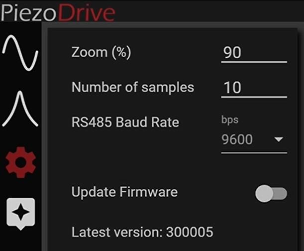
Firmware Update
After the first connection, the amplifier’s firmware needs to be updated to ensure compatibility
between the amplifier and desktop software. The firmware also needs to be updated after
downloading a new version of the desktop software. The desktop software will automatically
download the latest compatible version of the firmware; thus, it is import to check for new desktop
software periodically at: https://www.piezodrive.com/ultrasonic-drivers/pdus210-ultrasonic-driver/
The procedure for firmware update is:
 1 To update the firmware, click on the settings tab, then
 click the ‘Update Firmware’ switch. When the update
 firmware switch is on, the desktop software will begin
 downloading the latest firmware.
 Once the firmware has been downloaded, the software
 will prompt you to restart your amplifier (turn the power
 switch off and on). If your amplifier was already turned off,
 simply turn it on.
 2 Once the amplifier is reset, the desktop software will start
 the transfer. Do not interrupt this transfer. If the transfer
 fails or the device is not found, start the firmware update
 3 process again.

 4

 5

Offline Firmware Update
 If an internet connection is not available or you do not
 1 have access to Google servers. You can manually
 download the latest firmware from www.piezodrive.com.
 2 To ensure compatibility, also download the latest version
 of the desktop software.
 To perform a manual firmware update, press the ‘Load’
 3
 button at the bottom of the settings tab. Use the file
 browser to select the downloaded firmware. The software
 will now show the ‘File Loaded’ status. Click the update
 firmware switch and restart the PDUS210 when
 prompted. This update process has an identical result to
 the online procedure.

 PDUS210 V4 20 Modified 6/02/2021
Overview of Main Controls 1 Name Description 1 Enable Enables and disables the amplifier 2 Switch output. 3 Enabling the amplifier clears all present overloads. 4 2 Phase Enables and disables phase Tracking tracking. 5 Switch When enabled, the output frequency will be adjusted until the measured 6 phase equals the phase set point. When enabled, the output frequency cannot be manually changed. When the maximum frequency is encountered, the frequency will be 7 reset to the minimum, and vice- versa. 3 Current Enables and disables current Tracking tracking. Switch The output voltage will be adjusted 8 until the measured current equals the current setpoint. 9 When enabled, the output voltage 10 cannot be manually changed. Recommended when tracking a series resonance. Will disable power tracking 11 The voltage will not be adjusted until the phase tracking is locked, i.e. there is less than 10 degrees 12 difference between the measured phase and the phase set point. 4 Power Enables and disables power Tracking tracking. 13 Switch The output voltage will be adjusted until the measured load power 14 equals the power set point. When enabled, the output voltage cannot be manually changed. Will disable current tracking 15 The voltage will not be adjusted until the phase tracking is locked, i.e. 16 there is less than 10 degrees difference between the measured phase and the phase set point. 17 PDUS210 V4 21 Modified 6/02/2021
Name Description 5 Use Remote Enables and disables remote amplitude control. Amplitude Switch This will only work if the amplifier is enabled by the remote. When enabled, the remote dial will change the output voltage from zero to the maximum amplitude. If current tracking is enabled, the dial will change the current set point from zero to the maximum output current. If power tracking is enabled, the dial will change the power set point from zero to the maximum load power. 6 Output Voltage Shows and sets the output voltage, in Volts peak to peak. (V peak-peak) Cannot be changed if power or current tracking is enabled 7 Max Load Power Sets the maximum power that can be supplied to the load, in (W) Watts. If this maximum value is exceeded, an overload will be triggered and the amplifier output will be disabled. 8 Output Frequency Shows and sets the output frequency, in Hertz. (Hz) Cannot be changed if phase tracking is enabled. Limited to values between the minimum and maximum frequencies. 9 Minimum Output Shows and sets the minimum output frequency, in Hertz. Frequency (Hz) Limited to values between 5450 Hz and the maximum frequency. The operating frequency range should not exceed the output transformer specifications. 10 Maximum Output Shows and sets the maximum output frequency, in Hertz. Frequency (Hz) Limited to values between the minimum frequency and 520 kHz. The operating frequency range should not exceed the output transformer specifications. 11 Phase Setpoint Shows and sets the phase set point, in degrees. (Deg) 12 Phase Control Gain Shows and sets the control gain for phase tracking. Negative values are used to track a parallel resonance. Positive values are used to track a series resonance. Increasing the absolute value will increase the controller speed but may lead to instability. 13 Current Setpoint Shows and sets the current set point, in Amps peak. (A pk) 14 Current Control Shows/sets the controller gain for the current tracking controller. Gain Accepts only positive values. Increasing the value will increase the controller speed but may lead to instability. 15 Power Setpoint (W) Shows and sets the power set point, in Watts. 16 Power Control Gain Shows and sets the control gain for power tracking. Accepts only positive values. Increasing the value will increase the controller speed but may lead to instability. 17 Save On Device Saves all current settings to the amplifier non-volatile memory. PDUS210 V4 22 Modified 6/02/2021
Signal Graph 1 2 3 4 5 6 7 Name Description 1 Save Waveform Saves the displayed waveform to a csv file. 2 Pan Pans the plot. 3 Selection Zoom Drag over selection to zoom. 4 Resets Zoom Zooms out to the maximum values for the voltage and current. 5 Auto-scale Zooms to fit the voltage and current waveforms 6 Current waveform Current waveform, measured at 5.2 (M samples/s), 250 samples are displayed. 7 Voltage waveform Voltage waveform, measured at 5.2 (M samples/s), 250 samples are displayed. PDUS210 V4 23 Modified 6/02/2021
Frequency and Phase Graph 1 2 3 4 5 6 Name Description 1 Save to file Saves the traces for the frequency and phase to a csv file. Also saves the load power, amplifier power, temperature impedance, and RMS current. 2 Pan Pans the signals. 3 Zoom selection Drag over selection to zoom. 4 Reset zoom Zooms out or in to fit the bounds of the frequency and the phase signals. 5 Frequency Frequency signal sampled at approximately 5 samples/s. The signal number of samples stored can be changed in the settings tabs. 6 Phase signal Phase signal sampled at approximately 5 samples/s. The number of samples stored can be changed in the settings tabs. Small Graphs Graphs for the amplifier power, load power, temperature, impedance, and RMS current will appear when the software is maximized. These small graphs have the same controls as the frequency and phase graph. The save button for all of these graphs will save the frequency, phase, amplifier power, load power, temperature, impedance, RMS current, output voltage, phase setpoint, current setpoint, and power setpoint as a csv file. The number of samples saved is the same as the number of samples for the graphs, which can be changed in the settings tabs. This save function is recommended for any logging that may be required. PDUS210 V4 24 Modified 6/02/2021
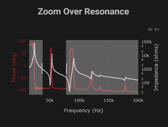
Assistant Quick Start Guide
To aid new users find settings for an ultrasonic load, the software provides an assistant tool. The
assistant tool has three key stages; the first will perform a wideband impedance sweep; the
second will perform a narrowband impedance sweep; and the last will perform analysis and apply
the determined settings. The procedure is:

 1. Select the Assistant tab

 2. Ensure the load is connected then
 press ‘Proceed’. The assistant will
1 perform an impedance sweep from
 15 kHz to 200 kHz.

 3. Zoom over the desired resonance;
 you may need to consult the
 transducer manufacturer if you do not
 know the operating frequency range.
 The assistant will start the second
 sweep over the selected region.

 2

 3

 PDUS210 V4 25 Modified 6/02/2021
4. Select either the series or parallel
 resonance. The assistant will give an
 estimate for the maximum power that
 can be achieved for each resonance. In
 this example, it can be seen that the
 maximum output power is 137 W for the
 series resonance and is limited by the
 maximum output voltage. For the
 parallel resonance case, the maximum
 output power is limited to 0.3 W. The
 reduction in output power is the result of
 poor impedance matching between the
4 load and the transformer. A far better
 model for operating at the parallel
 resonance would be PDUS210-800.

 5 5. Enter the desired load power; this will
 adjust either the current setpoint of the
 output voltage depending on the type of
 resonance selected. A series resonance
 will turn on current tracking, and parallel
 resonance will set the output voltage.

 6 6. Press track to apply the suggested
 settings and enable the amplifier. It is
 recommended that you save these
 settings to the amplifier.

 PDUS210 V4 26 Modified 6/02/2021
Frequency Sweep Function
 Impedance frequency responses are useful for diagnostics and identifying suitable
 operating ranges. The frequency response can be exported in csv format. To perform a
 manual sweep, select the sweep tab.

 Description
1
 Output voltage when performing the sweep. Higher
 1 voltages may decrease noise but may lead to
 overloads.
 The maximum load power. If the measured load
 power exceeds this value, an overload is triggered.
2 2
 This overload will stop the sweep and disable the
 amplifier output.
 3 Starting frequency for the sweep.
 4 End frequency for the sweep.
3
4 5 The frequency step or the resolution of the sweep.
5 The minimum delay between frequency steps. A
 longer delay provides greater settling time between
6 6
 frequencies, which may be required for systems
 with low damping or quality factor above 100.
7 8 9 7 Start sweep.
 8 Pause sweep.
 9 Stop sweep.

 PDUS210 V4 27 Modified 6/02/2021
Frequency Sweep Graph

 1 2 3 4

 5
 6

 Description
 1 Save the sweep data as a csv file
 2 Sets the impedance scale to log
 3 Sets the impedance scale to linear
 4 Auto-scale
 5 Phase data
 6 Impedance data

 PDUS210 V4 28 Modified 6/02/2021
PDUS210-FLEX Operation
The PDUS210-FLEX is identical to the standard PDUS210 except that it requires an external
transformer connected between the amplifier and transducer using the supplied cable. This allows
the user to switch between different output voltage ranges by changing the external transformer.
The PDUS210-FLEX must be purchased with at least one external transformer. The available part
numbers and specifications are listed in section

 PDUS210 V4 29 Modified 6/02/2021
PDUS210-FLEX Specifications. A kit containing six transformers ranging from 50 Vpk-pk to
800 Vpk-pk is also available (TX210-Kit1). This includes the following output voltage ranges: 50,
100, 200, 400, 600, and 800 Vpk-pk.

 Figure 7. PDUS210-FLEX Output transformer (e.g. TX210-800)

To operate the PDUS210-FLEX, the instructions are identical to the standard PDUS210 except for
the following steps that must be completed first, or when changing the transformer:
 1. Disconnect the amplifier from power and connect the desired transformer, e.g. TX210-800
 2. Connect the PDUS210-FLEX output to the transformer input, using the supplied cable
 3. Read the turns-ratio (N) from the transformer, or specifications table, and enter this into the
 textbox in the desktop software labelled ‘Turns Ratio’.
 4. Read the frequency range from Table 2. Then check that the Maximum and Minimum
 frequency settings in the desktop software are within this range.
 5. In the desktop software, press the ‘Save on Device’ button. This step is optional but will
 retain settings after cycling the power.

 PDUS210 V4 30 Modified 6/02/2021
Handheld Controller The handheld controller allows the PDUS210 to operate in a stand-alone mode. It is recommended that suitable settings are found using the assistant and then saved to the amplifier. The handheld controller can then be used to enable the amplifier and change the output amplitude. The amplitude knob on the controller adjusts either the output voltage, current, or power set point, depending on the selected operating mode. When the ON button is pressed momentarily, the PDUS210 is armed, which means the output is enabled but the output amplitude is set to zero. If the ON button is pressed and held, and tracking functions are enabled and the output is set to the value indicated by the amplitude knob. The shutdown button will disable the PDUS210 output. The shutdown button only works if the PDUS210 is enabled by the handheld controller. To operate the hand controller, the control functions are: Description 1,2 Slow alternating flash: armed, output is enabled but voltage is set to zero. Fast alternating flash: output is enabled but 1 tracking has not locked. 4 Solid green: output is enabled and tracking has 2 locked. 5 Solid red: output is disabled. 3 3 Adjusts the output amplitude from zero to the maximum. Adjusts the voltage, current, or power depending on the selected operating mode. 4 A short press enables the remote and arms the amplifier. Holding the switch on enables the output and any selected tracking functions. 5 Disables amplifier and remote. Only works if the amplifier is enabled with the remote. PDUS210 V4 31 Modified 6/02/2021
Custom Remote Controllers
PiezoDrive encourages the development of application specific remote controllers; for example, a
footswitch. The following schematic of the hand controller can be used as a template. The only
required components are the On and Shutdown switches. The dial functionality provided by the
variable resistor can be bypassed using the remote amplitude switch in the desktop software.
Alternatively, contact PiezoDrive for customization service.

 Figure 8. Hand controller schematic diagram

 Pin Name Limits Description
 0 Ground Ground
 1 Vs 3.3 V Supply voltage for the controller
 2 Amp 0 - 3.3 V Amplitude control from a 1k potentiometer
 3 On/Off 0 V low, 3.3 -10 V high On switch, active when high
 4 Status 0 V low, 3.3 V high High = enabled
 Low = disabled
 Slow toggle = armed
 Fast toggle = tracking in progress
 5 Shutdown 0 V low, 3.3 -10 V high Shutdown switch, active when high
 6 Ground 0V Ground
 7 Ground 0V Ground
 8 NC
 9 NC
 Table 5. Hand controller connector pinout.

 PDUS210 V4 32 Modified 6/02/2021
RS485 Interface
RS485 is a two-wire communication standard, commonly used for machine-to-machine, and
computer-to-machine communications (Introduction to RS485).
The PDUS210 responds to the commands described in https://github.com/PiezoDrive/RS485-API
For testing purposes or to control the amplifier from a PC, an RS485 USB cable is required, for
example, FTDI USB-RS485-WE-1800-BT. The connection diagram below is recommended. A
text-based application such as Putty can be used to send or receive commands.

 Ground A
 (Black) (Orange)
 B
 (Yellow)

 Baud Rates 9600, 115200, 460800, 921600
 Data Bits 8
 Stop Bits 1
 Parity None

 Table 6. RS485 Parameters

 Figure 9. USB-RS485-WE-1800-BT Cable

 PDUS210 V4 33 Modified 6/02/2021
Warranty and Service
The PDUS210 is guaranteed against manufacturing defects for 12 months from the date of
purchase.
Contact your distributor or info@piezodrive.com for service. Please include the amplifier serial
number.

 SI SI Scientific Instruments GmbH
 Roemerstr. 67 | 82205 Gilching
 +49 8105 77940
 info@si-gmbh.de
 www.si-gmbh.de
 Follow us on:

 PDUS210 V4 34 Modified 6/02/2021
You can also read