Single-phase pad-mounted step voltage regulator - Eaton
←
→
Page content transcription
If your browser does not render page correctly, please read the page content below

Voltage Regulators
Catalog Data                                                  COOPER POWER
                                                                                                      SERIES
                       Effective January 2022
CA225002EN             Supersedes June 2016

Single-phase pad-mounted step
voltage regulator

             General
             Eaton's Cooper Power™ series single-phase             The pad-mounted voltage regulator provides
             pad-mounted voltage regulators add a dimension        state-of-the-art voltage regulation while reducing
             to underground system planning. They provide          installation costs and preserving site aesthetics.
             system planners freedom to improve the                Pad-mounted voltage regulators, in conjunction
             safety, reliability, and power quality in existing    with pad-mounted transformers and switchgear,
             and new underground distribution systems.             can be used to create a modular pad-mounted
             The pad-mounted voltage regulator provides all        substation. This substation can be placed in areas
             the functionality of traditional round-tank pole-     that require a low profile installation. It can exist
             mounted and substation voltage regulators, with       inconspicuously and quite possibly utilize shared
             the convenience of pad-mounting.                      rights-of-way.
             The pad-mounted voltage regulator provides step-
             type voltage regulation in thirty-two (32) steps
             of approximately 5/8% each for a maximum of
             ± 10% regulation when used singly or in wye-
             connected banks. Voltage ratings are available
             from 2500 volts (60 kV BIL) to 34,500 volts (150
             kV BIL) for 60 Hz and 50 Hz systems.
             Control of the voltage regulator is microprocessor-
             based, with a digital metering package of Class
             1 accuracy. Instantaneous metering, time/date-
             stamped demand metering, and profile recording
             are provided. Features include voltage limiting
             capability, voltage reduction capability, reverse
             power flow operation, and tap position tracking.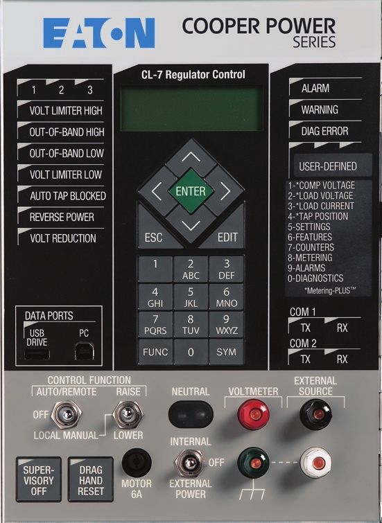
Catalog Data CA225002EN                                                    Single-phase pad-mounted step voltage regulators
Effective January 2022

Catalog number information                                                  kVA Rating
Use Table 1 as a guide when ordering voltage regulators or to               07 = 76.2
interpret a voltage regulator catalog number.
                                                                            10 = 100

Table 1. Voltage regulator catalog number system                            11 = 110, 114.3
                                                                            14 = 144
 Description                                              Catalog Number    15 = 152
 Base letters for a voltage regulator                     VR                16 = 167
 Physical Configuration                                                     20 = 200
 P = Pad - 1PH - ONAN rated                                                 21 = 219
 W = Pad - 1PH - ONAN rated w/IDPT                                          22 = 220
 X = Pad - 1PH - ONAN/ONAF rated                                            25 = 250
 Y = Pad - 1PH - ONAN/ONAF rated w/IDPT                                     28 = 288                                   VRXXXX
 I = Pad - 2-in-1 - ONAN rated                                              33 = 333
 J = Pad - 2-in-1 - ONAN rated w/IDPT                                       40 = 400
 K = Pad - 2-in-1 - ONAN/ONAF rated                                         41 = 416.3
 L = Pad - 2-in-1 - ONAN/ONAF rated w/IDPT                                  43 = 432
 M = Pad - 2-in-1 - Open delta connected - ONAN rated                       44 = 440
 N = Pad - 2-in-1 - Open delta connected - ONAN rated                       50 = 500
 w/IDPT
                                                                            57 = 576
 Q = Pad - 2-in-1 - Open delta connected - ONAN/ONAF      VRX
 rated                                                                      66 = 660, 667
 Z = Pad - 2-in-1 - Open delta connected - ONAN/ONAF                        69 = 690
 rated w/IDPT
                                                                            83 = 833
 R = Pad - 3-in-1 - ONAN rated
                                                                            SP = Special
 T = Pad - 3-in-1 - ONAN rated w/IDPT
                                                                            Losses
 U = Pad - 3-in-1 - ONAN/ONAF rated
                                                                            B = Std.
 V = Pad - 3-in-1 - ONAN/ONAF rated w/IDPT
                                                                            C = Std. type A with control winding
 H = Pad - 3-in-1 - Delta connected - ONAN rated
                                                                            F = Low loss
 B = Pad - 3-in-1 - Delta connected - ONAN rated w/IDPT
                                                                            G = Low loss type A with control winding
 D = Pad - 3-in-1 - Delta connected - ONAN/ONAF rated                                                                  VRXXXXX
                                                                            H = Special evaluation
 G = Pad - 3-in-1 - Delta connected - ONAN/ONAF rated
 w/IDPT                                                                     V = Reoptimized

 S = Special                                                                X = Reoptimized low loss

 Nominal Voltage Rating                                                     Z = Optimized

 1 = 2500                                                                   S = Special

 3 = 7620                                                                   Control Identifier

 5 = 14400                                                                  000 = None                                 VRXXXXXXXX

 6 = 19920                                                                  CL7 = CL-7

 8 = 34500                                                VRXX              System Usage

 9 = Special 60Hz                                                           1 = Single-phase regulator

 D = 11000                                                                  2 = 2-in-1 regulator                       VRXXXXXXXXX

 N = 22000                                                                  3 = 3-in-1 regulator

 R = 33000                                                                  4 = 3-phase metering (LTC)

 X = Special 50Hz                                                           Random Alphanumeric Character              VRXXXXXXXXXXXXXXX
                                                                            Tap Changer Revision
                                                                            A = QD3 (T350)
                                                                                                                       VRXXXXXXXXXXXXXXXX
                                                                            G = QD5 (T556)
                                                                            N = QD8 (T875)

2                    www.eaton.com/cooperpowerseries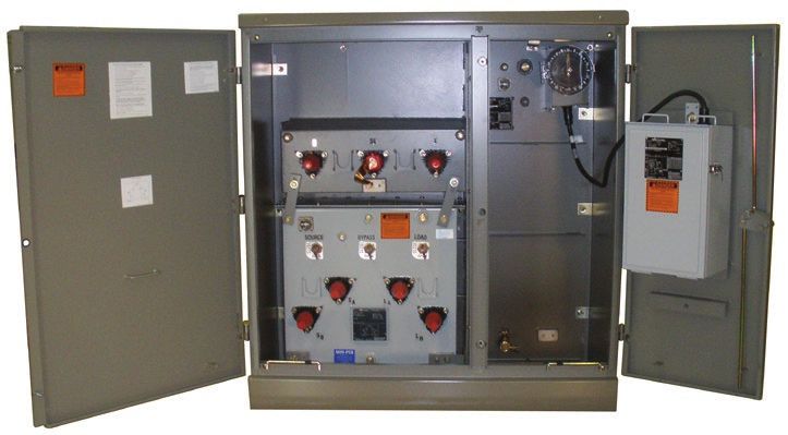
Single-phase pad-mounted step voltage regulators                                                                          Catalog Data CA225002EN
                                                                                                                                         Effective January 2022

                    Full metal barrier separating the                                                  Automatic pressure relief device
                                 two compartments           Bolted oil tank cover                                      Oil level gauge
         Parking stand (2)                                                                                                      Tap changer position indicator
                                  Lifting lugs (2)                                                                              and junction box
                                     (not shown)
                Bushing wells & inserts or                                                                                                Laser engraved
                      600 A terminations                                                                                                  nameplates (2)

                                                                                                          1" filter press       Ground
                                                                                                          connection and        pad          Control box with
             Sectionalizing switches                                                                      fill plug
             • Source                                Optional bypass switch module                                                           CL-7 control
             • Bypass                                                                          1" drain valve
             • Load                                                                            with sampler

Figure 1. The pad-mounted voltage regulator is delivered fully-equipped, ready for your application.

Standard features                                                                   •   Deep removable cabinet

A sealed tank construction combined with a 65 °C average winding
                                                                                    •   Automatic pressure relief device
rise insulation system provides a proven design for long life                       •   Lifting lugs
installations. Additional capacity is available through the ADD-AMP™                •   Under-oil series arrester (3 or 6 kV)
feature.
                                                                                    •   Provisions for pressure/vacuum gauge & thermometer
Internal construction allows easy removal of the interior assembly. A
bolted cover also provides a large area to perform maintenance with                 •   1" filter press connection and fill plug
the assembly in the tank.                                                           •   Control box with CL-7 control
•   Full metal barrier separating the two compartments                              •   Oil level gauge
•   Two parking stands                                                              •   Junction box and position indicator
•   Three bushing wells & inserts, 600 A or 900 A terminations                      •   1" drain valve with sampler
•   Standard “pad-mounted green” paint (Munsell 7GY3.29/1.5)                        •   Control cable disconnect at junction box and control box
•   Ground pads                                                                     •   Line-side lift-off door secured with two captivated bolts
•   Bolted oil tank cover                                                           •   Pad-lockable lift-off control-side door with three-point latching
•   Nameplates (2)                                                                  •   Door position-retention rods
•   Internal differential PT                                                        •   Faceplate-mounted tap changer for PT taps

                                                                                                                www.eaton.com/cooperpowerseries                  3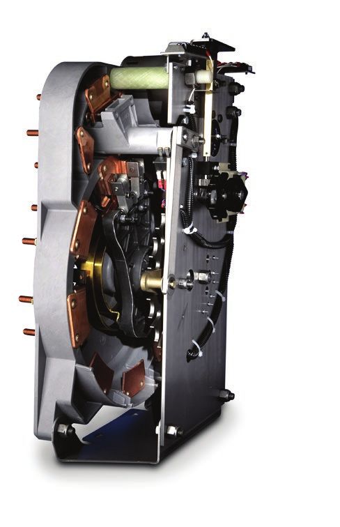
Catalog Data CA225002EN                                                                      Single-phase pad-mounted step voltage regulators
Effective January 2022

                                                                                                                             OVERALL WIDTH

                                                                                                            S                SL                    L

                                                                                                                                                               NP

                                                                                                          SOURCE        BYPASS            LOAD

                                                                                              HEIGHT
                                                                                                                        SA        L
                                                                                                                                      A

                                                                                                                S
                                                                                                                          NP              L
                                                                                                                                              B
                                                                                                                    B

                                     OVERALL DEPTH
Figure 2. Single-phase pad-mounted voltage regulator and optional bypass switch module.

 Table 2. Pad-Mounted Voltage Regulator Weights and
 Dimensions 60 Hz                                                                                          DEPTH                                                WIDTH
 Voltage       Height        Overall             Overall              Total
 (Volts)       (in.)         Width (in.)         Depth (in.)          Weight (Ibs.)
                                                                                                                                                  SOURCE       BYPASS           LOAD

 2500          50 - 65       55 - 65             50 - 65              3000 - 6000

                                                                                                                                                                                        HEIGHT
 7620          50 - 65       55 - 65             50 - 85              3000 - 7000
                                                                                                                                                               SA       L
                                                                                                                                                                            A
 14400         50 - 70       55 - 65             50 - 75              3000 - 7000
                                                                                                                                                                 NP             L
 19920         50 - 70       55 - 75             50 - 85              3500 - 8500
                                                                                                                                                       S                            B
                                                                                                                                                           B

 34500         50 - 70       55 - 75             50 - 90              8000 - 10000
Note: Some ratings include corrugate cooling. Weights and dimensions are
      for reference only and are not for construction. Please contact Eaton for
      exact dimensions.                                                                      Figure 3. Bypass switch module (optional).

    Table 3. Pad-Mounted Voltage Regulator Weights and
    Dimensions 50 Hz
    Voltage         Height           Overall              Overall          Total Weight
    (Volts)         (mm)           Width (mm)           Depth (mm)             (Kg)
    11000      1250 - 1650         1400 - 1650          1250 - 1900        1300 - 3175
    22000      1250 - 1800         1400 - 1900          1250 - 2200        1300 - 3900
    33000      1250 - 1800         1400 - 1900          1250 - 2300        3100 - 4500

Note: Some ratings include corrugate cooling. Weights and dimensions are
      for reference only and are not for construction. Please contact Eaton
      for exact dimensions.

    Table 4. Bypass Switch Module Weights and Dimensions
                                                                      Overall
    Voltage   Current                                                 Depth         Weight
    (Volts)   (Amperes)       Height (in.)         Width (in)         (in.)         (lbs.)

              200             30                   30                 12            400
    All       400             36                   36                 12            525
              550             36                   36                 12            550

Note: Weights and dimensions are for reference only and are not for
      construction. Please contact Eaton for exact dimensions.

4                    www.eaton.com/cooperpowerseries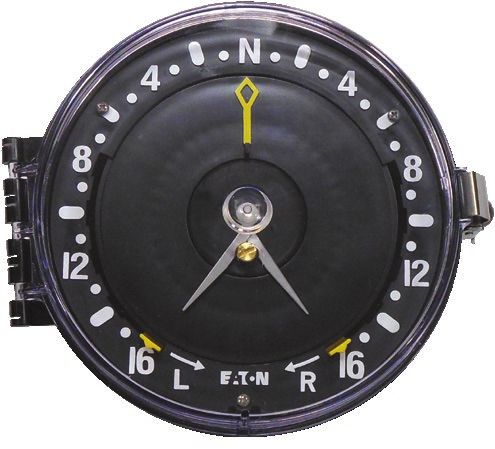
Single-phase pad-mounted step voltage regulators                                                                                                             Catalog Data CA225002EN
                                                                                                                                                                                Effective January 2022

Optional accessories                                                                                       Ease of operation
•    Bypass switch module (550 A ratings and below, grounded-wye                                           The control box is mounted on the door of the operational side of
     systems only)                                                                                         the cabinet for easy access. As the operator uses the control, the
•    FR3™ dielectric fluid                                                                                 position indicator is in clear view.
•    40" deep cabinet                                                                                      The junction box has a removable side door which permits access to
                                                                                                           the terminal block for the connections from the tank to the control
•    Alternate top coat color                                                                              cable. The control is connected from the control box to the junction
•    No barrier                                                                                            box with a quick-disconnect control cable, which enables easy
                                                                                                           removal. The current transformer is automatically shorted when the
•    Pressure/vacuum gauge (with or without alarm contacts)                                                cable is removed.
•    Dial-type thermometer (with or without alarm contacts)
•    Alarm contacts for oil level gauge
•    Under-oil shunt arresters
•    Nameplates in alternate languages and/or metric units
•    Elbow shunt arresters
•    Position indicator (PI) viewing window
•    Infrared (IR) window
•    External 2X control box
•    IEC bushings (50Hz designs)
     • Includes PI Viewing window and external 2X box as standard

    Table 5. Regulator Voltage Ratings and Corresponding Terminations
    Voltage (Volts)               Current (Amperes)                                   kVA                                          Bushing                                                     BIL

    60 Hz Ratings
    2500                          400                                                 100                                          600 A integral bushing                                      60
    2500                          668, 875                                            167, 219                                     900 A integral bushing                                      60
    7620                          100, 150, 200                                       76, 114, 152                                 200 A well & 15 kV class insert                             95
    7620                          328, 438, 548                                       250, 333, 416                                600 A integral bushing                                      95
    7620                          656, 875                                            500, 667                                     900 A integral bushing                                      95
    14400                         50, 100, 200                                        144, 288                                     200 A well & 25 kV class insert                             125*
    14400                         300, 400, 463, 578                                  432, 576, 667, 833                           600 A integral bushing                                      125*
    19920                         100, 200                                            200, 400                                     600 A integral bushing                                      150
    19920                         335                                                 667                                          600 A integral bushing                                      150
    34500                         200                                                 690                                          600 A integral bushing                                      150
    50 Hz Ratings
    11000                         100, 200                                            110, 220                                     200 A well & 15 kV class insert                             95
    22000                         100, 200                                            220, 440                                     200 A well & 25 kV class insert                             125*
                                  300                                                 660                                          600 A integral bushing                                      150
    33000                         200                                                 660                                          600 A integral bushing                                      150

Note: The 7620 V units rated 200 A or less are available with optional 25 kV class inserts. The 125 kV BIL rating is only limited by the bushing: all internal connections are designed and constructed to 150 kV
      BIL. A 600 A, 150 kV BIL integral bushing is available as an option. 600 A or 900 A bushing upgrades are available as well for each voltage ratings.

                                                                                                                                              www.eaton.com/cooperpowerseries                                  5
Catalog Data CA225002EN                                                                                Single-phase pad-mounted step voltage regulators
Effective January 2022

Position indicator and ADD-AMP™ feature
Exclusive to Eaton, the uniquely designed position indicator offers
corrosion resistant materials, an oversized viewing area and a
reset solenoid that is replaceable using a single thumbscrew. It is
mounted on a junction box on the frontplate of the regulator and
is directly connected to the tap changer by a flexible drive shaft
passing through the junction box and terminal board via a sealing
gland.
The indicator face is graduated in steps, numbered 1 through 16
on each side of neutral. Drag hands indicate the maximum and
minimum positions attained during raise and lower operations. The
drag hands are reset around the position indicator hand by operating
the drag hand reset switch on the voltage regulator control.
The ADD-AMP feature of the pad-mounted voltage regulator allows
increased current capacity by reducing the regulation range. The
CL-7 control also allows for an Adaptive ADD-AMP feature which
will automatically change the Soft ADD-AMP setting based upon the
current readings of the control.
This is accomplished by either setting limit switches in the position
indicator (HARD-ADD-AMP feature) or enabling the SOFT-ADD-AMP
feature to prevent the tap changer from traveling beyond a set
position in either raise or lower directions. The limit switches have                                  Figure 4. Position indicator.
scales graduated in percent regulation, and are adjustable to specific
values of 5, 6-1/4, 7-1/2, 8-3/4, and 10%.
The five possible load current ratings associated with the reduced
regulation ranges are summarized in Tables 6 and 7. At each setting,
a detent stop provides positive adjustment. Settings other than
those with stops are not recommended. The raise and lower limits
need not be the same value, except for locations where reverse
power flow is possible.

 Table 6. Regulator Voltage Ratings
    Voltage
    Rating                                                             Standard Internal Tap Settings
 60 Hz:
 2500 V             2500              2400
 7620 V             8000              7970               7620               7200              6930           4800       4160           2400
 14400 V            14400             13800              13200              12000             7970           7620       7200           6930
 19920 V            19920             17200              16000              15242             14400          7970       7620           7200
 34500 V            34500             19920
 50 Hz:
 11000 V            11600             11000              10000              6930              6600           6350       6000           5500
 22000 V            23000             22000              20000              19100             15000          12700      11000          10000
 33000 V            33000             30000              22000              20000             11600          11000      10000

Note: Other ratings may be available upon request. Contact your Eaton representative for more information.
* Limited by the bushing interface.
‡ Regulators are capable of carrying current corresponding to rated kVA when operated at 7200 volts.

6                       www.eaton.com/cooperpowerseries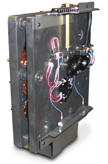
Single-phase pad-mounted step voltage regulators                                                                                                       Catalog Data CA225002EN
                                                                                                                                                                         Effective January 2022

 Table 7. ADD-AMP Capabilities of 60 Hz Ratings
                                                  Load Current Rating (Amperes)
                                                  Regulation Range
 Rated Voltage            Rated kVA               ±10%                     ±8.75%                  ±7.50%                ±6.25%                 ±5%

                          100                     400                      440                     480                   540                    6402
 2500                     167                     668                      668                     668                   668                    668
                          219                     875                      -                       -                     -                      -
                          76                      100                      110                     120                   135                    160
                          114                     150                      165                     180                   2031                   2401
                          152                     200                      2201                    2401                  2701                   3201
                          250                     328                      361                     394                   443                    525
 7620*
                          333                     438                      482                     526                   591                    6682
                          416                     548                      6032                    6582                  6682                   6682
                          500                     656                      668                     668                   668                    668
                          667                     875                      875                     875                   875                    875
                          144                     100                      110                     120                   135                    160
                          288                     200                      220                     240                   270                    320
                          432                     300                      330                     360                   405                    480
 14400
                          576                     400                      440                     480                   540                    6402
                          667                     463                      509                     556                   6252                   6682
                          833                     578                      636                     668                   668                    668
                          200                     100                      110                     120                   135                    160
 19920                    400                     200                      220                     240                   270                    320
                          667                     335                      369                     402                   452                    536
 34500                    690                     200                      220                     240                   270                    320

1 Requires bushings upgraded to 600 A
2 Requires bushings upgraded to 900 A
* Regulators are capable of carrying current corresponding to rated kVA when operated at 7200 volts.
Note: Per IEEE Std C57.15-2017™ standard, single-phase regulators rated 668 A and below shall have the continuous current rating or 668 A, whichever is less, as shown
      in the table. To achieve 668 A, the bushings must be upgraded to 900 A.

                                                                                                                                         www.eaton.com/cooperpowerseries                     7
Catalog Data CA225002EN                                                                                Single-phase pad-mounted step voltage regulators
Effective January 2022

 Table 8. ADD-AMP Capabilities of 50 Hz Ratings
                                          Load Current Rating (Amperes)
                                          Regulation Range
 Rated
 Voltage              Rated kVA           ±10%               ±8.75%              ±7.50%             ±6.25%              ±5%

                      110                 100                110                 120                135                 160
 11000
                      220                 200                2201                2401               2701                3201
                      100                 50                 55                  60                 68                  80
 22000                220                 100                110                 120                135                 160
                      330                 150                165                 180                2031                2401
 33000                660                 200                2201                2401               2701                3201

1 Requires bushings upgraded to 600 A
Note: Per IEEE Std C57.15-2017™ standard, single-phase regulators up to 19.9 kV rated 668 A and below shall have the continuous current
      rating or 668 A, whichever is less, as shown in the table. To achieve 668 A, the bushings must be upgraded to 900 A.

8                      www.eaton.com/cooperpowerseries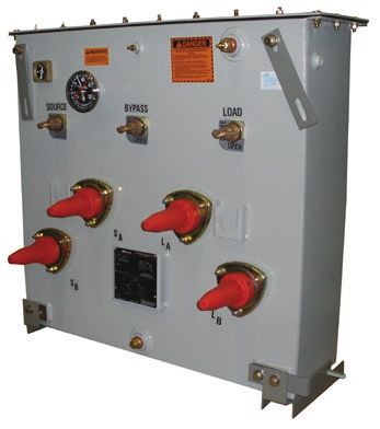
Single-phase pad-mounted step voltage regulators                                                                          Catalog Data CA225002EN
                                                                                                                                        Effective January 2022

Bypass switch module (Optional)
As with round tank regulators, bypassing a pad-mounted voltage
regulator is an option in system operation. Installing or removing the
pad-mounted voltage regulator from the circuit is accomplished with
a stand-alone bypass switch module.
This switch module fits inside the secure regulator cabinet during
normal operation. When the regulator needs to be removed, the
bypass module provides hotstick–operable sectionalizing switches
to disconnect the regulator from the system without causing
interruption to the downstream load.

 Table 9. Bypass Switch Ratings
 Voltage (Volts)       Current (Amperes)     Bushings

                       200                   200 A wells and 15 & 25 kV inserts with
                                             removable studs
 All                   400                   600 A integral bushings
                       550                   600 A integral bushings                      Figure 6. Bypass switch module.

                             PAD-MOUNTED VOLTAGE REGULATOR

                                   SERIES
                                   WINDING

                                                       SHUNT
                                                       WINDING
                             SOURCE-LOAD
                                BUSHING                                 LOAD
                   SOURCE     (EXTERNALLY                              BUSHING
                   BUSHING     GROUNDED)

                                CABLING FROM
                                REGULATOR TO
                                BYPASS SWITCH MODULE

                              BYPASS SWITCH MODULE

                                        NORMALLY
                                        OPEN
                                        BYPASS
                                        SWITCH

           NORMALLY                                               NORMALLY
            CLOSED                                                 CLOSED
            SOURCE                                                  LOAD
          DISCONNECT                                             DISCONNECT
             SWITCH                                                SWITCH

                                                                                          Figure 7. Voltage regulator bypassing operation.

 FEEDER                                                                          FEEDER
 SOURCE                                                                           LOAD

Figure 5. One-line diagram of pad-mounted regulator with
bypass switch module for grounded-wye applications.

                                                                                                                www.eaton.com/cooperpowerseries             9
Catalog Data CA225002EN Single-phase pad-mounted step voltage regulators
Effective January 2022
CL-7 series control
• Source-side voltage calculated from tap position
• Internal-external voltage source switch
• Automatic/manual control switch
• Manual raise/lower toggle switch
• Position indicator drag hand reset switch
• Supervisory ON-OFF switch for use with SCADA
• Alpha-numeric keypad
• 4x20 character display
• Multilingual display
• Three date formats
• Six-digit operations counter
• Voltage test terminals
• External voltage source terminals
• Neutral indicating dual LEDS
• Panel-mounted motor fuse
• Metering-PLUS™ one-touch, grouped-data display feature
• Tap-position tracking
• Voltage limiting ("First House Protection")
• Line drop compensation settings
• SOFT-ADD-AMP feature with adaptive functionality
• Duty Cycle Monitor (DCM)
• TIME-ON-TAP™ tap position tracking feature
• Preventative Maintenance Tapping (PMT™) feature
• Tap-to-neutral
• Voltage reduction with 5 modes
• Digital metering package (including instantaneous, demand and
time-tagged demand) Figure 8. CL-7 regulator control.
• Data profiler
• Configurable status alarms
• Configurable data alarms CL-7 optional accessories
• Event record • Multi-phase functionality
• Local data retrieval USB front port • Front panel overlays in alternate languages
• PC data port • Serial communications interfaces:
• Resident communications protocols: DNP3, IEC 60870-5, 2179, • RS232
MODBUS Serial and MODBUS TCP/IP • Fiber optic - ST
• Programmable I/O using logical equations • RS485
• Alternate configuration settings • Ethernet communications interfaces:
• Fiber optic - LC, MTRJ, ST, and SC
• Copper - RJ45
• 8 input/8 output universal contacts
• 13.5 Vdc radio power supply
• 13A-Hr control power battery backup
• 48/125 Vdc substation battery power interface
• 240 V external source interface
• Auxiliary analog input module (4-20 mA inputs)
10 www.eaton.com/cooperpowerseriesSingle-phase pad-mounted step voltage regulators Catalog Data CA225002EN
Effective January 2022
Construction
Core and coil assembly
The coil assembly features aluminum strip in the series winding
that achieves the optimum in ampere turn balance for exceptional
strength under through-fault conditions.
Grain-oriented steel is used in the core, with a low reluctance lap
joint. The rugged core clamp assembly secures the coil effectively
and positions the core for the optimum in quiet operation and low
core losses.
Quik-Drive tap changers
The load tap-changer product offering consists of three Quik-Drive™
tap changers; the most advanced tap changers in the industry.
Each device is sized for a specific range of current and voltage
applications and share many similarities in their construction.
The primary benefits of Quik-Drive tap changers are: direct motor
drive for simplicity and reliability, high-speed tapping operation
for faster voltage regulation operation and proven mechanical life
(one million operations). Common Quik-Drive tap changer features
include: neutral light switch, position indicator drive, safety switches
and logic switches (back-off switches) and a motor holding switch.
Quik-Drive load tap changers meet IEEE™ and IEC standards for
mechanical, electrical and thermal performance.
Figure 10. QD-3 Quik-Drive tap changer.
Figure 9. QD-8 Quik-Drive tap changer. Figure 11. QD-5 Quik-Drive tap changer.
www.eaton.com/cooperpowerseries 11Catalog Data CA225002EN Single-phase pad-mounted step voltage regulators
Effective January 2022
This page is intentionally left blank.
12 www.eaton.com/cooperpowerseriesSingle-phase pad-mounted step voltage regulators Catalog Data CA225002EN
Effective January 2022
This page is intentionally left blank.
www.eaton.com/cooperpowerseries 13Catalog Data CA225002EN Single-phase pad-mounted step voltage regulators
Effective January 2022
Eaton
1000 Eaton Boulevard
Cleveland, OH 44122
United States
Eaton.com
Eaton’s Power Systems Division
2300 Badger Drive
Waukesha, WI 53188
United States
Eaton.com/cooperpowerseries
© 2022 Eaton
All Rights Reserved
Printed in USA Eaton is a registered trademark.
Publication No. CA225002EN All other trademarks are property
January 2022 of their respective owners.You can also read