SMD I2C Digital Ambient Light Sensor - ALS-PDIC17-79NB/TR8
←
→
Page content transcription
If your browser does not render page correctly, please read the page content below
SMD I2C Digital Ambient Light Sensor
ALS-PDIC17-79NB/TR8
Features
• Close to the human eye's response
• 15 bit effective resolution
• 50Hz/60Hz rejection
• Low sensitivity variation across various light sources
o o
• Operating temperature performance, -40 C to 85 C
• Wide supply voltage range, 2.7V to 5.5V
• Low power consumption, less than 2mW while operating
• Shut-down mode, current consumption less than 0.1uA
2
• I C serial port communication: (1) Standard 100kHz, (2).Fast 400kHz
• High dynamic sensing range and from 0 to 88,400 Lux
• Size: 2.0mm(L)*2.0mm(W)*0.6mm(H)
• RoHS compliant and Pb Free
Description
2
The ALS-PDIC17-79NB/TR8 is a digital-output light sensor with a two-wire, I C serial interface that is compatible with
SMBus when working at 100kHz serial clock frequency. It combines a photodiode and an analog-to-digital converter
(ADC) on a single CMOS integrated circuit to provide light measurements over an effective 15-bit dynamic range. Two
operation modes are provided with one for constantly refreshing ADC and the other for one time integration. When
working in “one time integration” mode, no external resister is required. The integrating conversion technique used by
ALS-PDIC17-79NB/TR8 effectively eliminates the effect of flicker from AC-powered lamps, increasing the stability of
the measurement. ALS-PDIC17-79NB/TR8 wavelength is close to human-eye, and low response to non-visible light,
such as infrared and ultra-violet light.
Applications
• Detection of ambient light for controlling the backlighting of TFT LCD display
• Automatic residential and commercial lighting management
• Automatic contrast enhancement for electronic signboard
• Ambient light monitoring device for daylight and artificial light
1 Copyright
Revision :3 © 2010, Everlight All Rights Reserved. Release Date : 3.5.2012. Issue No: DLS-0000034
Release Date:2012-03-16
12:00:33.0
www.everlight.com
LifecyclePhase: Expired Period: Forever
DATASHEET
SMD I2C Digital Ambient Light Sensor
ALS-PDIC17-79NB/TR8
Absolute Maximum Ratings (Ta=25 )
Parameter Symbol Rating Unit
Storage Temperature TSTG -40 ~ 100
Operating Temperature TOPR -40 ~ 85
Supply Voltage VDD -0.3 ~ 6 V
Digital Output Voltage VO -0.3 ~ 6 V
Digital Output Current IO -10 ~ 10 mA
ESD Tolerance
ESDHBM 3500 V
(Human Body Model)
ESD Tolerance
ESDMM 150 V
(Machine Model)
Block Diagram & Pad Descriptions
Figure 1 ALS-PDIC17-79NB/TR8 Functional Block Diagram
2 Copyright
Revision :3 © Release Date:2012-03-16
2010, Everlight All Rights Reserved. Release Date : 3.5.2012. Issue No: DLS-0000034 12:00:33.0
www.everlight.com
LifecyclePhase: Expired Period: Forever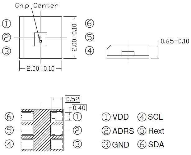
DATASHEET
SMD I2C Digital Ambient Light Sensor
ALS-PDIC17-79NB/TR8
Pad Description
Pad I/O Function
VDD Power Supply Voltage
GND Power Power and signal return
REXT Input Connecting a resistor to GND for adjusting integration time
2
SDA I/O I C data input/output terminal
2
SCL Input I C derail clock input terminal
2
ADRS I/P I C address option pad
Electro-Optical Characteristics (Ta=25 )
Parameter Symbol Min. Typ. Max. Unit Condition
Active Mode Supply Current IDD ----- 0.4 0.5 mA VDD=3.3V
Power-Down Mode Supply Current IDDQ ----- ----- 0.1 μA VDD=3.3V
Detection Full Counts ----- ----- 32767 Counts
Detection Limit ----- 44200 ----- Lux TINT=100mS
Peak Sensitivity Wavelength λP ----- 550 ----- nm
VDD=3.3V
Response in Dark Environment RDAK ----- ---- 1 Count EV=0Lux
TINT=100ms
VDD=3.3V
Response in Fluorescent Light RFRST100 44 73 102 Counts EV=100Lux
TINT=100mS
VDD=3.3V
Response in Fluorescent Light RFRST1000 440 730 1020 Counts EV=1000Lux
TINT=100mS
Note:
1. Fluorescent light (Color Temperature = 6500K) is used as light source. However, White LED is substituted in mass production.
3 Copyright
Revision :3 © Release Date:2012-03-16
2010, Everlight All Rights Reserved. Release Date : 3.5.2012. Issue No: DLS-0000034 12:00:33.0
www.everlight.com
LifecyclePhase: Expired Period: Forever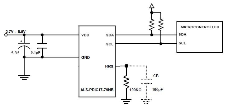
DATASHEET
SMD I2C Digital Ambient Light Sensor
ALS-PDIC17-79NB/TR8
DC Characteristics of I2C Signals in Standard and Fast Mode
Standard Mode Fast Mode
Parameter Symbol Unit
Min. Max. Min. Max
Power Supply Voltage
VDD 2.7 5.5 2.7 5.5 V
(Recommend)
Low Level Input Voltage VIL -0.5 1 -0.5 1 V
High Level Input Voltage VIH ----- VDD*0.6 ----- VDD*0.6 V
Hysteresis of Schmitt trigger inputs
VHYS 0.05*VDD ----- 0.05*VDD ----- V
(VDD > 2V)
Low level output voltage (open
drain) at 3mA sink current (VDD > VOL1 0 0.4 0 0.4 V
2V)
Output fall time from VIHMIN to
[2]
VILMAX with a bus capacitance from TOF ----- 250
[2]
20+0.1Cb
[1] 250 nS
10pF to 400pF
Input current of each IO pins with
an input voltage between 0.1VDD IINPUT -10 10 -10 10 μA
and 0.9VDD
Capacitance for each IO pin CI ----- 10 ----- 10 pF
Note:
1. Cb = capacitance of one bus line in pF
2
2. The maximum tr for the I C data and clock bus lines quoted in the AC table is longer than the specified maximum TOF for the output
2 2
stages (250nS). This allows series protection resistors (Rs) to be connected between I C data / clock pins and the I C data / clock bus
lines without exceeding the maximum specified tf.
4 Copyright
Revision :3 © Release Date:2012-03-16
2010, Everlight All Rights Reserved. Release Date : 3.5.2012. Issue No: DLS-0000034 12:00:33.0
www.everlight.com
LifecyclePhase: Expired Period: ForeverDATASHEET
SMD I2C Digital Ambient Light Sensor
ALS-PDIC17-79NB/TR8
AC Characteristics of I2C Signals in Standard and Fast Mode
Standard Mode Fast Mode
Parameter Symbol Unit
Min. Max. Min. Max
2
I C clock frequency fSCL 0 100 0 400 KHz
Hold time (repeated) START
condition. After this period, the first tHD;STA 4.0 0.6 - us
clock pulse is generated.
2
Low period of I C clock tLOW 4.7 1.3 us
2
High period of I C clock tHIGH 4.0 0.6 us
Set-up time for a repeated START
tSU;STA 4.7 0.6 us
condition
2
Data hold time for I C-bus devices tHD;DAT 0 3.45 0 0.9 us
Data set-up time tSU;DAT 250 - 100 - ns
2
Rise time of both I C data and
tr - 1000 5 300 ns
clock signal’s
2
Fall time of both I C data and clock
tf - 300 0.1 300 ns
signal’s
Set-up time for STOP condition tSU;STO 4.0 - 0.6 - us
Bus free time between STOP and
tBUF 4.7 - 1.3 - us
START condition
Capacitive load for each bus line Cb - 400 - 400 pF
2
Figure 2 I C Timing Diagram
5 Copyright
Revision :3 © Release Date:2012-03-16
2010, Everlight All Rights Reserved. Release Date : 3.5.2012. Issue No: DLS-0000034 12:00:33.0
www.everlight.com
LifecyclePhase: Expired Period: ForeverDATASHEET
SMD I2C Digital Ambient Light Sensor
ALS-PDIC17-79NB/TR8
Typical Electro-Optical Characteristics Curves
Fig 3 Light Output vs. Illuminance (Ta=25 ) Fig 4 Current Consumption vs. Illuminance (Ta=25 )
Fig 5 Current Consumption vs. Supply Voltage (Ta=25 ) Fig 6 Dark Count vs. Supply Voltage (Ta=25 )
Fig 7 Light Counts vs. Supply Voltage (Ta=25 ) Fig 8 Current Consumption vs. Temperature
6 Copyright
Revision :3 © Release Date:2012-03-16
2010, Everlight All Rights Reserved. Release Date : 3.5.2012. Issue No: DLS-0000034 12:00:33.0
www.everlight.com
LifecyclePhase: Expired Period: ForeverDATASHEET
SMD I2C Digital Ambient Light Sensor
ALS-PDIC17-79NB/TR8
Fig 9 Dark Count vs. Temperature Fig 10 Light Counts vs. Temperature
Fig 11 Spectrum Fig 12 Relative Sensitivity vs. Angle
Communication Protocol
2
ALS-PDIC17-79NB contains an 8-bit command register that can be written and read via the I C bus. The
command register controls the overall operation of the device. There is a two-byte word read-only register that contains
2
the latest converted value of A/D converter. The I C slave address is hardwired internally as 00111001 (0x39, MSB to
LSB, A6 to A0). All the Send Byte protocol, the Receive Byte protocol and Receive Word protocol are implemented in
ALS-PDIC17-79NB.
The Send Byte protocol allows single bytes of data to be written to the device (see Figure 13-a). The written byte
is called the COMMAND byte. The Receive Byte protocol allows one-byte data to be read from the device (see Figure
13-b). Two-byte data can be read by following the Receive Word Protocol shown in Figure 13-c. In Figure 13, the clear
area represents data sent by the host (master) and the shaded area represents data returned by the ambient light
sensor (slave device).
7 Copyright
Revision :3 © Release Date:2012-03-16
2010, Everlight All Rights Reserved. Release Date : 3.5.2012. Issue No: DLS-0000034 12:00:33.0
www.everlight.com
LifecyclePhase: Expired Period: ForeverDATASHEET
SMD I2C Digital Ambient Light Sensor
ALS-PDIC17-79NB/TR8
1 7 1 1 8 1 1
S Slave Address WR A Command Byte A P
0 0 0
(a) Send byte protocol
1 7 1 1 8 1 1
S Slave Address RD A Data NA P
1 0 1
(b) Receive byte protocol
1 7 1 1 8 1 8 1 1
S Slave Address RD A LS byte of ADC A MS byte of ADC NA P
1 0 0 1
(c) Receive word (two bytes) protocol
S = start condition P = stop condition Shaded = slave transmission
A = acknowledge NA = not acknowledge WR = write RD= read
Figure 13 Communication Protocol
Communication Format
2 2
ALS-PDIC17-79NB is capable of working as an I C slave. Address of this device on I C bus is always 0x39
2
(hexadecimal number 39). Registers of the slave device can be programmed by sending commands over I C bus.
2
Figure 14 shows an I C write operation. To write to an internal register of the slave device a command must be
2 2
sent by an I C master. As illustrated in Figure 14, the I C write command begins with a start condition. After the start
condition, seven bits of address are sent with MSB going first. RD / WRn (=Low) command bit follows the address bits.
2
Upon receiving a valid address the slave device responds by driving SDA low for an ACK. After receiving an ACK, I C
2
master sends eight bits of data with MSB first. Upon receiving eight bits of data the slave device generates an ACK. I C
master terminates this write command with a stop condition.
2
Figure 14 I C Timing Diagram for Send Byte Format
8 Copyright
Revision :3 © Release Date:2012-03-16
2010, Everlight All Rights Reserved. Release Date : 3.5.2012. Issue No: DLS-0000034 12:00:33.0
www.everlight.com
LifecyclePhase: Expired Period: ForeverDATASHEET
SMD I2C Digital Ambient Light Sensor
ALS-PDIC17-79NB/TR8
Figure 15 shows an I2C read command sent by the master to the slave device. I2C read command
begins with a start condition. After the start condition seven bits of address are sent by the master with
MSB going first. After the address bits, RD / WRn command bit is sent. For a read command the RD / WRn
bits is high. Upon receiving the address bits and RD / WRn command bits the slave device responds with
an ACK. After sending an ACK, the slave device sends eight bits of data with MSB going first. After receiving
the one byte data, the I2C master terminates this transaction by issuing a NACK command to indicate that
the master only wanted to read one byte from the device. The master generates a stop condition to end
this transaction.
2
Figure 15 I C Timing Diagram for Receive Byte Format
Ambient light intensity count value can be obtained by reading registers of this device. Ambient light intensity
count is a 15-bit wide number plus a valid bit and hence word (two bytes) read operation is needed, as shown in Figure
2
16. After receiving the two byte data, the I C master terminates this transaction by issuing a NACK command to indicate
that the master only wanted to read two bytes from the device. The master generates a stop condition to end this
transaction.
2
Figure 16 I C Timing Diagram for Receive Word Format
9 Copyright
Revision :3 © Release Date:2012-03-16
2010, Everlight All Rights Reserved. Release Date : 3.5.2012. Issue No: DLS-0000034 12:00:33.0
www.everlight.com
LifecyclePhase: Expired Period: ForeverDATASHEET
SMD I2C Digital Ambient Light Sensor
ALS-PDIC17-79NB/TR8
Theory of Operation
The photocurrent, generated by the built-in photodiode while being illuminated, is proportionally converted to
frequency; the digital frequency signal is then integrated by a 15-bit counter for a predetermined period of time (Tint).
This period of time is called integration time which can be adjusted by changing the nominal value of the resistor
2
between the RINT and GND terminals. The converted data are read out through a two-wire, I C Interface bus. Since the
photodiode has been specially processed to suppress the spectral response in infrared region, the readout is very close
to the photopic transfer function, v(λ), which is the mathematic expression of human-eye's response to ambient light.
Address Option for I2C
2
The I C address is determined before placing an order; users can assign any one of the three addresses (0x39,
0x29, 0x44) for their specific application. Without any prior request for a specific I2C address, the default address is
0x39.
Address Pin
I2C Address
Configuration
Floating 0x39 (default)
Tied to GND 0x29
Tied to VCC 0x44
2
Table 1 Connecting options of I C address
ADC Register
The ADC register contains 16 bits with a 15-bit wide data from D0 to D14 and a valid bit D15. The register is
divided into two groups; D[15..8] is the most significant (MS) byte and D[7..0] is the least significant (LS) byte. See Table
2 for details.
Valid Bit Data Bits
D15 D14 D13 ~ D8 D7~D1 D0
MSB LSB
Most Significant (MS) byte Least Significant (LS) byte
Table 2 ADC Register Structure
10 Copyright
Revision :3 © Release Date:2012-03-16
2010, Everlight All Rights Reserved. Release Date : 3.5.2012. Issue No: DLS-0000034 12:00:33.0
www.everlight.com
LifecyclePhase: Expired Period: ForeverDATASHEET
SMD I2C Digital Ambient Light Sensor
ALS-PDIC17-79NB/TR8
Device Command
There are eight command codes are provided for I2C master to control the ambient light sensor. The specific
function corresponding to each command code is elaborate in Table 3.
Command
Function
Code
Shut-down mode, this is the default state after applying VDD power to the
device. During shut-down mode, users can do the communication test.
1xxx_xxxx
Except the MSB must be logic 1, the value written to the command
(binary code)
register will not change any function and can be read back via the I2C bus
by issuing Receive Byte Protocol.
Activate the ambient light sensor and put the device in [continuous
operation mode], The ADC register will be refreshed every Tint
0x0C
integration time which is set by an external resistor Rext. See Table 4 for
details.
Activate the ambient light sensor and put the device in [one time
0x04 integration mode]. The integration time is controlled by I2C commands,
start and stop integration.
Start integration: This command will reset the ADC register to 0x0000
0x08 and begin a new integration in [one time integration mode]. This is an
invalid command in [continuous operation mode].
Stop integration: This command will stop the integration in [one time
0x30 integration mode] and set the valid bit ( D[15] ) high. This is an invalid
command in [continuous operation mode].
Table 3 Command Code List
11 Copyright
Revision :3 © Release Date:2012-03-16
2010, Everlight All Rights Reserved. Release Date : 3.5.2012. Issue No: DLS-0000034 12:00:33.0
www.everlight.com
LifecyclePhase: Expired Period: ForeverDATASHEET
SMD I2C Digital Ambient Light Sensor
ALS-PDIC17-79NB/TR8
Programming Sequence
Case 1: Using internal integration timing
(1). After being powered on, the device will initially be in the shut-down mode (default setting).
(2). To operate the device, issue an Send Byte protocol (see Figure 13-a) with the device address 0x39 followed by a
command byte of 0x0C to activate the ambient light sensor and put the device into "continuous operation mode".
(3). To read the ADC conversion result, issue an Receive Word protocol (see Figure 13-c) with the device address
0x39 followed by two-byte reading procedures.
(4). If a conversion has not been completed since being activated, the valid bit ( D[15] ) will be 0 to indicate that the
data is not valid. If there is a valid conversion result available, the valid bit ( D[15] ) will be set logic high, and the
remaining 15 bits will represent valid data from the ADC register.
(5). Data may be read repeatedly from the ADC register, and although it will remain valid, the ADC register will not be
updated until a new conversion completes.
Case 2: Using external integration timing
(1). After being powered on, the device will initially be in the shut-down mode (default setting).
(2). To operate the device, issue an Send Byte protocol (see Figure 13-a) with the device address 0x39 followed by a
command byte of 0x04 to activate the ambient light sensor and put the device into "one time integration mode".
2
(3). I C master sends a "start integration command" to the salve device by issuing Send Byte protocol with the device
address 0x39 followed by a command byte of binary code (1xxx_xxxx).
2
(4). After a period of user defined integration time, I C master sends a "stop integration command" to the salve device by
issuing Send Byte protocol with the device address 0x39 followed by a command byte of 0x30.
(5). To read the ADC conversion result, issue an Receive Word protocol (see Figure 13-c) with the device address 0x39
followed by two-byte reading procedures.
(6). If the stop integration command is not received by the device, the valid bit (D [15]) will be “0” to indicate that the data
is not valid. If there is a valid conversion result available, the valid bit (D [15]) will be set logic high, and the
remaining 15 bits will represent valid data from the ADC register.
(7). Data may be read repeatedly from the ADC register, and although it will remain valid, the ADC register will not be
updated until a new complete integration cycle has been carried out.
In both cases, the power consumption of the device can be reduced by issue an Send Byte protocol with the
device address 0x39 followed by a data byte of 1xxx_xxxx.(Binary code)
12 Copyright
Revision :3 © Release Date:2012-03-16
2010, Everlight All Rights Reserved. Release Date : 3.5.2012. Issue No: DLS-0000034 12:00:33.0
www.everlight.com
LifecyclePhase: Expired Period: ForeverDATASHEET
SMD I2C Digital Ambient Light Sensor
ALS-PDIC17-79NB/TR8
Noise Rejection and Integration Time
In general, integrating type ADC’s have an excellent noise rejection characteristics for periodic noise sources
whose frequency is an integer multiple of the integration time. For instance, a 60Hz AC unwanted signal’s sum from 0ms
to n*16.66ms (n = 1, 2...ni) is zero. Similarly, setting the ALS-PDIC17-79NB integration time to an integer multiple of
periodic noise signal greatly improves the light sensor output signal in the presence of noise. The integration time, Tint,
of the ALS-PDIC17-79NB is set by an external resistor Rext. The maximum detection range is inversely proportional to
the integration time; that means the longer integration time the lower detection range.
Rext Integration time Detection range Resolution
(KΩ) ( mS ) ( Lux ) ( Lux / Count )
50
50 88,400 2.7
(min.)
100
100 44,200 1.35
(recommended)
200 200 22,200 0.68
300 300 14,500 0.45
400
400 11,100 0.34
(max.)
Table 4 Rext Resistor Selection Guide
In order to achieve both 60Hz and 50Hz AC rejection, the integration time needs to be adjusted to coincide with
an integer multiple of the AC noise cycle times. To determine a suitable integration time, Tint, that will ignore the
presence of both 60Hz and 50Hz noise, users can use the formula:
Tint = n(1/60Hz) = m(1/50Hz), where n and m are integers.
n/m = 60Hz/50Hz = 6/5.
The first instance of integer values at which Tint rejects both 60Hz and 50Hz is when m = 5, and n = 6, thus,
Tint = 6(1/60Hz) = 5(1/50Hz) = 100ms,
Rext = Tint* (100kΩ/100ms) = 100kΩ, (see Table 4)
By populating Rext = 100kΩ, ALS-PDIC17-79NB defaults to 100ms integration time in continuous operation
mode, and will reject the presence of both 60Hz and 50Hz power line signals. When working in one-time integration
mode, the master must control the integration time to be an integer multiple of 100ms.
13 Copyright
Revision :3 © Release Date:2012-03-16
2010, Everlight All Rights Reserved. Release Date : 3.5.2012. Issue No: DLS-0000034 12:00:33.0
www.everlight.com
LifecyclePhase: Expired Period: ForeverDATASHEET
SMD I2C Digital Ambient Light Sensor
ALS-PDIC17-79NB/TR8
Power Supply Decoupling and Layout
The power supply lines must be decoupled with capacitors, 4.7uF and 0.1uF, placed as close to the device
package as possible. The bypass capacitor should have low effective series resistance (ESR) and effective series
inductance (ESI), such as the common ceramic types, which provide a low impedance path to ground at high
frequencies to handle transient currents caused by internal logic switching. ALS-PDIC17-79NB is relatively insensitive to
2
layout. Like other I C devices, it is intended to provide excellent performance even in significantly noisy environments.
2
There are only a few considerations that will ensure best performance. Route the supply and I C traces as far as
possible from all sources of noise. Use two power-supply decoupling capacitors, 4.7µF and 0.1µF, placed close to the
device.
Rext is not required working
in " one time integration "
mode.
CB is optional for long
distance connection when
14 Copyright
Revision :3 © Release Date:2012-03-16
2010, Everlight All Rights Reserved. Release Date : 3.5.2012. Issue No: DLS-0000034 12:00:33.0
www.everlight.com
LifecyclePhase: Expired Period: ForeverDATASHEET
SMD I2C Digital Ambient Light Sensor
ALS-PDIC17-79NB/TR8
Package Dimensions
Note: Tolerances unless mentioned ±0.1mm. Unit = mm
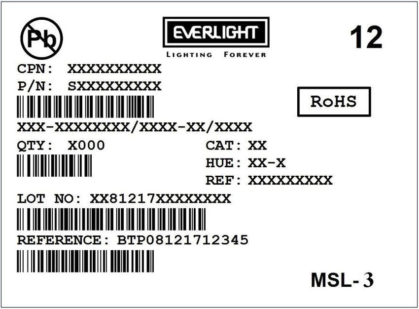
Moisture Resistant Packing Materials
Label Explanation
‧CPN: Customer’s Product Number
‧P/N: Product Number
‧QTY: Packing Quantity
‧CAT: Luminous Intensity Rank
‧HUE: Dom. Wavelength Rank
‧REF: Forward Voltage Rank
‧LOT No: Lot Number
15 Copyright
Revision :3 © Release Date:2012-03-16
2010, Everlight All Rights Reserved. Release Date : 3.5.2012. Issue No: DLS-0000034 12:00:33.0
www.everlight.com
LifecyclePhase: Expired Period: ForeverDATASHEET
SMD I2C Digital Ambient Light Sensor
ALS-PDIC17-79NB/TR8
Reel Dimensions
Carrier Tape Dimensions: Loaded Quantity 2000 pcs Per Reel
W E F
8.00 0.20 1.75 0.10 3.50 0.05
D0 D1 P0
1.50+0.10
1.00 0.10 4.00 0.05
-0
P1 P2 t
4.00 0.10 2.00 0.05 0.23 0.05
A0 B0 K0
2.15 0.05 2.15 0.05 0.95 0.05
Note: Tolerances unless mentioned ±0.1mm. Unit = mm
Moisture Resistant Packing Process
16 Copyright
Revision :3 © Release Date:2012-03-16
2010, Everlight All Rights Reserved. Release Date : 3.5.2012. Issue No: DLS-0000034 12:00:33.0
www.everlight.com
LifecyclePhase: Expired Period: ForeverDATASHEET
SMD I2C Digital Ambient Light Sensor
ALS-PDIC17-79NB/TR8
Recommended method of storage
1. Do not open moisture proof bag before devices are ready to use.
2. Shelf life in sealed bag from the bag seal date: 18 months at 10°C~30°C and < 90% RH.
3. After opening the package, the devices must be stored at 10°C~30°C and 60%RH, and used within 168 hours (floor
life).
4. If the moisture absorbent material (desiccant material) has faded or unopened bag has exceeded the shelf life or
devices (out of bag) have exceeded the floor life, baking treatment is required.
5. If baking is required, refer to IPC/JEDEC J-STD-033 for bake procedure or recommend the following conditions:
192 hours at 40°C +5/–0°C and < 5 % RH (reeled/tubed/loose units) or
96 hours at 60°C ± 5°C and < 5 % RH (reeled/tubed/loose units) or
24 hours at 125°C ± 5°C, not suitable for reel or tubes.
Recommended Solder Profile
Notice:
1. Reflow soldering should not be done more than two times.
2. When soldering, do not put stress on the devices during heating.
3. After soldering, do not warp the circuit board.
4. Reference: IPC/JEDEC J-STD-020D
5. Recommend soldering pad as drawing.
17 Copyright
Revision :3 © Release Date:2012-03-16
2010, Everlight All Rights Reserved. Release Date : 3.5.2012. Issue No: DLS-0000034 12:00:33.0
www.everlight.com
LifecyclePhase: Expired Period: ForeverDATASHEET
SMD I2C Digital Ambient Light Sensor
ALS-PDIC17-79NB/TR8
Soldering Iron
Each terminal is to go to the tip of soldering iron temperature less than 350 for 3 seconds within once in less
than the soldering iron capacity 25W. Leave two seconds and more intervals, and do soldering of each terminal. Be
careful because the damage of the product is often started at the time of the hand solder.
Repairing
Repair should not be done after the device have been soldered. When repairing is unavoidable, a double-head
soldering iron should be used (as below figure). It should be confirmed beforehand whether the characteristics of the
device will or will not be damaged by repairing.
18 Copyright
Revision :3 © Release Date:2012-03-16
2010, Everlight All Rights Reserved. Release Date : 3.5.2012. Issue No: DLS-0000034 12:00:33.0
www.everlight.com
LifecyclePhase: Expired Period: ForeverDATASHEET
SMD I2C Digital Ambient Light Sensor
ALS-PDIC17-79NB/TR8
Note:
1. Above specification may be changed without notice. EVERLIGHT will reserve authority on material change for above
specification.
2. When using this product, please observe the absolute maximum ratings and the instructions for using outlined in these
specification sheets. EVERLIGHT assumes no responsibility for any damage resulting from use of the product which
does not comply with the absolute maximum ratings and the instructions included in these specification sheets.
3. These specification sheets include materials protected under copyright of EVERLIGHT corporation. Please don’t
reproduce or cause anyone to reproduce them without EVERLIGHT’s consent.
19 Copyright
Revision :3 © Release Date:2012-03-16
2010, Everlight All Rights Reserved. Release Date : 3.5.2012. Issue No: DLS-0000034 12:00:33.0
www.everlight.com
LifecyclePhase: Expired Period: ForeverYou can also read