SOLUTION AIR HANDLING UNITS - 2000 TO 100,000 CFM (Indoor & Outdoor Models)
←
→
Page content transcription
If your browser does not render page correctly, please read the page content below

FORM 102.20-QG1 (808)

                     V
                     F
                     D                                                                                    V
               FPC                                                                                        F
                                                                                                          D

                                                                                                                EA

DP HF XA       FS                 XA        CC        XA HC RF                     MB               FE
SA
                                                                                                     RA
                          Split
                                                                                                              ld08301

                         FS            DI        RF        XA            DP

       Split

                                                                                              VFD        EA

                         VC                 XA        HC        RF            MB         FE
                                                                                        RA
                                                                     Split
                                                                                                              ld08302

SOLUTION AIR HANDLING UNITS
                  2000 TO 100,000 CFM
               (Indoor & Outdoor Models)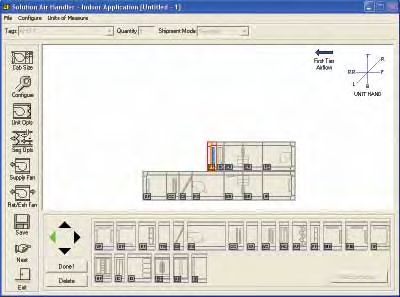
FORM 102.20-QG1 (808)

TABLE OF CONTENTS

GENERAL INFORMATION                                                            STAGGERED COIL OPTIONS
  Introduction ............................................................3      Angle Wall ............................................................32
  A Proud History of Experience & Qualifications .....3                           Back-to-Back ........................................................32
  Assurance of Johnson Controls Backing ...............3                          Multizone (MC) .....................................................33
  Computer Selection Programs ...............................4                 HEATING SEGMENTS
  Innovative Engineering & Design ...........................5                    Integral Face & Bypass ........................................34
  Flexibility of Design ................................................6         Indirect Gas-Fired ................................................35
  Superior Casing Performance ................................6                   Turndown Examples and Guidelines....................36
  Pre-engineered Packaged Controls .......................7                       Electric Heat Options & Applications ....................37
  Customized Variable Size Openings ......................7                    ENERGY RECOVERY
  Airflow Measurement Performance ........................8                       Heat Wheel ..........................................................40
  State-of-the-Art Certification & Testing ...................8
                                                                               FILTER SEGMENTS
  New Sound Testing Laboratory ..............................8
                                                                                  Applications & Options Table ...............................41
  Quality Construction Equals Improved IAQ............9
                                                                                  Mechanical Air Filters ...........................................42
  Multi-Sloped Drain Pans ........................................9
                                                                                  MERV Analysis .....................................................43
  Raceways...............................................................9
                                                                               MIXING SEGMENTS & ECONOMIZERS
  Improve Cost Savings ............................................9
                                                                                 Mixing Box /Economizers .....................................44
  A Complete Line of Filters ....................................10
                                                                                 Mixing Box Optimization Chart .............................46
  Energy Saving Fan Options .................................10
                                                                                 Typical Economizer Application............................47
  Energy Consumption............................................11
                                                                                 Building Pressurization.........................................47
  Sound Attenuation ................................................13
                                                                                 Methods of Pressurization Control .......................48
  Inertia Base ..........................................................13
                                                                                 Economizer Arrangements ...................................48
  Quick Selection ....................................................14
                                                                                 Face Damper .......................................................49
FAN APPLICATION REVIEW
                                                                                 Inlet Plenum .........................................................49
  Fan Laws .............................................................15
                                                                               ACCESSORY SEGMENTS
  Variable Air Volume ..............................................16
                                                                                 Diffuser Segment .................................................50
  Component Temperature Margins ........................17
                                                                                 Access Segment ..................................................50
  Fan Motor Heat ....................................................17
                                                                                 Vertical Plenum ...................................................51
COIL OPTIONS
                                                                                 Discharge Plenum ................................................51
  Cooling Coils ........................................................18
                                                                                 Sound Attenuator .................................................52
  Heating Coils ........................................................19
                                                                                 Noise and Vibration ..............................................53
  Typical Application of AH Coils .............................20
                                                                                 Air Blender - Mixers..............................................54
SOLUTION SEGMENT IDENTIFICATION                                                  Face & Bypass Damper Segment ........................55
  Segment Listing ...................................................21          Turning Segments ................................................56
  Unit & Coil Hand Selection ...................................21               Humidifier Segment..............................................56
FAN SEGMENTS – FS, FR, FE                                                        UV Segment .........................................................57
  Fan Applications ...................................................22         Pipe Chase Enclosure..........................................58
  Dual Fan Considerations......................................22                Roof Curb .............................................................58
  Dual Fan Applications ..........................................22             Special Curb Requests ........................................59
  Door and Discharge Locations .............................23                 CONTROLS
  Single Fan DWDI Options ....................................24                 F. P. Controls & Motor Control Centers ................60
  Single Fan SWSI Options ....................................25                 Typical FPC Wiring...............................................60
  Dual Fan DWDI Options.......................................26                 Software Process .................................................61
  Dual Fan SWSI Options .......................................27                Field Equipment Controller...................................61
  SWSI vs. DWDI ....................................................28           Power Wiring Options ..........................................62
  Fan Motor Control Methods .................................29
                                                                               INDUSTRY FORMULAS
COIL SEGMENTS                                                                    Miscellaneous Industry Formulas.........................63
  Cooling (CC) ........................................................30
                                                                               GUIDE SPECIFICATIONS WITH TIPS
  Heating (HC) ........................................................30
                                                                                 Part 1 - General....................................................64
  Vertical Coil (VC) ..................................................31
                                                                                 Part 2 - Products ..................................................67
                                                                                 Part 3 - Execution.................................................81
2                                                                                                                               JOHNSON CONTROLS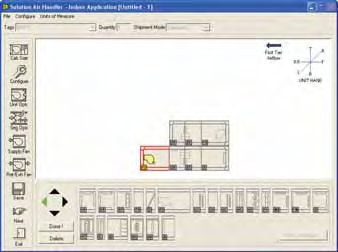
FORM 102.20-QG1 (808)

GENERAL INFORMATION

Introduction                                                      Assurance of Johnson Controls Backing
This Equipment Guide will provide engineers with                  With every Solution system, you get the support and
a summary of Solution air handling information in the             resources that come from dealing with a worldwide
most convenient, time-saving manner possible. The                 manufacturer – JOHNSON CONTROLS. You are not
guide will direct you to various sources of data and infor-       tied to the limitations of a regional supplier. Instead, you
mation helpful in solving questions concerning product            get the flexibility being able to design in one part of the
options, design application, as well as installation and          country, and buy and install in another location.
operation.
                                                                  Johnson Controls Factory Service
A Proud History of Experience & Qualifications
                                                                  Turn to the experts at Johnson Controls/YORK.
Johnson Controls combined with YORK heating, ventila-             Johnson Controls/York carries the burden of single-
tion, air-conditioning, and refrigeration (HVAC&R) sys-           source responsibility since Johnson Controls/YORK
tems and solutions creates the largest global provider of         packages the total system, including custom air han-
integrated products, systems and services for the $200            dlers, chillers, controls, and variable air-volume boxes
billion global building environment industry.                     and building automation systems. For added peace
                                                                  of mind, Johnson Controls/YORK offers Inspection
Johnson Controls/YORK is:                                         Only, Preventive Maintenance and Inspection, or Total
 • A global leader in control systems and services                Service Contracts to meet your specific financing and
   for heating, ventilating, air conditioning (HVAC),             management requirements. Johnson Controls service
   lighting, security and fire management for non-                can also provide certified technicians available locally
   residential buildings, facility management and                 for factory start-up, drawing from over 700 factory-
   consulting services.                                           trained service technicians in 100 strategically-located
                                                                  offices nationwide – a capability not offered by indepen-
 • Represented in over 125 countries, including
                                                                  dent manufacturers.
   North America, Asia, Europe, the Middle East,
   Africa and Latin America and in all markets.
       ®                                                          Full Service Support
YORK Solution® air-handling units (AHUs) from John-
son Controls–the only names you need to know for a line           Because JOHNSON CONTROLS factory packaged
that has no limits. Johnson Controls/YORK engineers               devices and motor controls are an integral part of the
have developed an AHU line that is so flexible, and able          equipment, who better to troubleshoot and service the
to deliver such high standards of performance, that it can        system than a professional Johnson Controls Service
handle virtually any application. Whatever the air-han-           Technician. The Johnson Controls Service technician
dling challenge–IAQ, acoustics, energy, controls, you             knows not only the equipment and the hardware, but
name it–Johnson Controls/YORK can build a Solution                also has a working knowledge of equipment applica-
AHU that will meet your needs.                                    tion and operation. Every unit is backed by this kind of
                                                                  professional support.
Solution® AHU’s from Johnson Controls
comprise a complete AHU line to meet commercial,
institutional and industrial indoor and outdoor unit              Development and Preparation of Service Literature
applications. For more than 50 years, YORK air
                                                                  Johnson Controls/YORK produces quality product
handling units have been installed in every type of facility to
                                                                  literature to ensure proper installation, operation and
handle any type of requirement; manufacturing, education,
                                                                  maintenance. Installation, Operation and Maintenance
healthcare, life sciences and process manufacturing.
                                                                  manuals must be followed to realize the full capacity
Solution® AHU’s come equipped with industry-leading               and life of the units. In addition, literature supplements
Metasys® controls that are installed and commissioned             of special characteristics and features are distributed as
at the factory. Factory installation assures superior             required to support regular product enhancements.
quality, saves time on the jobsite and delivers accurate
performance. Plus, you can count on seamless opera-
tion with a Metasys building management system.

JOHNSON CONTROLS                                                                                                            3
FORM 102.20-QG1 (808)
GENERAL INFORMATION
Computer Selection Programs This powerful software tool brings flexibility and com-
puting power to the desktop of designers. The software
YORKworks™ software is the primary source for the
allows you and the customer to make product decisions
latest product design and performance data.
and view performance data in a user-friendly, step-by-
1. Includes the latest innovations, updates, and ef- step, screen-driven environment.
ficiencies of YORK® products
YORKworksCE™ software is a necessity for your
2. Includes general functionality used to select customer’s engineering toolbox. YORKworks revolution-
equipment factory packaged controls. izes the way you specify HVAC equipment. Johnson
Controls/YORK can optimize the selection of any air
3. Sound data for air-handling units
handling unit for a specific job requirement with its
4. All screens are interconnected and are continually computer selection programs.
updated according to configuration inputs.
Quick and Easy selection
• Save Time – choose components and
complete configurations with a couple
of clicks.
• Reduce Errors – use pre-programmed
rules and guidelines for component
selection.
Just Click to
select and add
components
Literature Reference — see ‘Sales Guide – YORK works CE’ Form 70.02-SG1
4 JOHNSON CONTROLSFORM 102.20-QG1 (808)
Innovative Engineering & Design 5. Solution’s Variable Aspect Ratio eliminates the
need for costly modifications.
Solution Air Handlers are not just ‘fans-in-a-box’!
6. Solution fits the specification and the space!
1. Solution is a structure that withstands deflection
2. Solution is a sound/noise barrier Innovative Engineering & Design allows you to choose
from a limitless variety of configurations. See con-
3. Solution is a container of clean and conditioned air
figurations below for some of the popular applications
4. Solution is an integral part of a building’s fire and designed to meet your particular need.
safety plans
Configuration 1 (Stacked Unit) – Configuration 2 (Stacked Unit) –
Mechanical room favorite. Reduced footprint with tiered Ultra-quiet design with plenum fan and U-shaped
supply fan cabinet
AT DP
FS
TN
TN
VC XA HC FM
FS XA EH XA RF MB
Configuration 3 – Minimum frills. Maximum IAQ
FS CC XA HC FF MB
Configuration 4 – Exhaust air flexibility with gas-heat and humidification
DP HM XA IG XA FS CC AF EE FE
Configuration 5 – Cooling-only lab design with HEPA filtration
DP HF XA DI FS CC RF MB
Configuration 6 – Classic hospital design with return fan economizer operation.
DP RF XA DI FS CC XA HC AF EE FR
JOHNSON CONTROLS 5FORM 102.20-QG1 (808)
GENERAL INFORMATION
Flexibility of Design Component Flexibility
Solution AHUs offer the ultimate in dimensional, mate- AHUs are responsible for providing
rial, and component flexibility. Solution AHUs have the the environment with quality indoor
same appeal for both “standard” and “custom” markets. air, in an energy efficient and quiet
How an air-handling unit is designed and built deter- manner. Solution AHUs help meet
mines how well it performs. that responsibility by offering every
available component, from energy
Engineering Flexibility wheels to air-monitoring stations
to specialty-purpose filters. As
• Variable cabinet dimensions
technology creates new capabilities, Johnson Controls/
• Material and component flexibility YORK will apply these to our Solution line.
• Full line of factory packaged controls installed, Superior Casing Performance
tested and commissioned by Johnson Controls
The foam injected panels of our Solution air handling
certified technicians
units enhance performance, maximizing the indoor air
• Variable sized inlet and discharge openings quality and help to create ASHRAE 62-2000 compliant
designs while reducing costs. The direct result of the
• Indoor and outdoor constructions
foam injection insulation is a rigid panel, low leakage,
• Tiered (stacked) and custom configurations high pressure air handler, with increased energy sav-
ings, and reduced initial cost.
Better IAQ
Deflection presents a potential in leaks that form over
time from the operational pressure. The foam injected
Solution panels are 20% more rigid (L/240 vs. L/200)
then the typical fiberglass or foam board construction.
In addition the smaller deflections can be achieved using
lighter sheet metal gauges then required by fiberglass
construction. The result is a lower initial cost unit with
greater performance.
Lower leakage reduces the infiltration of unfiltered and
unconditioned air into the space. The infiltration of un-
• Panels are individually removable without affect- conditioned air can lead to condensation in unit walls,
ing structural integrity. crevices and/or insulation. When the infiltration occurs
in a negative pressure atmosphere downstream of the
Dimensional Flexibility filter, it will lead to unfiltered air being supplied to the
space. Maintaining a low leakage for positive pressure
You can design Solution AHUs to fit the application and
segments reduces the loss of conditioned air to a po-
the space. Length, height and width can all be varied
tentially warm and humid ambient environment, causing
to match building constraints. With hundreds of cross-
increased condensation. Condensation can lead to
sectional possibilities, you choose the best match for the
premature corrosion as well as IAQ concerns.
application. In addition, all Solution AHU components
have been designed with a variable-aspect ratio to meet The Solution foam injected wall panels help to seal and
your space and air-velocity requirements. maintain the leakage at maximum of 1% with a minimum
+/-8” of static pressure. Options for a maximum leakage
Material Flexibility rate of 1/2% at a minimum of +/-10” of static pressure
are available for those projects which demand it.
A complete line of construction materials are available,
including galvanized steel, aluminum, painted steel, Coil carryover, humidification, and periodic wash downs
stainless steel, and more. Solution AHUs can handle are all instances where water is present in the unit.
a multitude of environments, from the most benign to Foam insulated panels will not absorb, and retain water,
the most corrosive. NOTE: All units/unit segments are like a fiberglass insulated panel will. In addition the ther-
shrink-wrapped to protect unit from contamination dur- mal properties of foam are not degraded by an incident
ing shipping where the insulation comes in contact with water.
6 JOHNSON CONTROLSFORM 102.20-QG1 (808)
Energy Savings Factory Installation
The energy savings associated with high performing air Factory installation improves quality and saves time.
handler construction is directly associated with leakage While a Solution AHU is being manufactured, Johnson
and insulating properties. Controls technicians can easily access all its segments.
So there are no accessibility problems to cramp the
The infiltration of unconditioned air downstream of a coil,
quality of the controls installation, which often occurs
or the loss of conditioned air downstream of a coil are
on the jobsite.
just two examples of reduced energy efficiency in an air
handler. The foam injected panel helps to reduce both All sensor probes have been pre-engineered to deter-
of these potential losses by creating a more rigid, lower mine the best mounting location, ensuring accurate and
leakage air handling over the life of the unit. reliable readings.
Another form of energy loss associated with air handlers This improves performance of the unit while eliminat-
is the thermal energy that is lost through the cabinet of ing unwanted air leakage common in field-mounted
the air handler. The Solution foam injected panels lower solutions.
energy consumption with better insulating properties.
With the standard R-12.5 and optional R-18.8, or R-25, Factory engineering speeds field connections
the Solution can help to reduce the energy usage. The
The goal is to provide
injected panel provides additional thermal advantages in
you with an AHU that
that the foam will fill voids, and gaps that aren’t reached
simplifies field connec-
with fiberglass or foam board type constructions.
tion of the controls. For
Solution air handler units are capable of being factory example, coil valves
tested to prove out both leakage and deflection. With are shipped uninstalled,
the Solution product it’s not all about construction, it’s but pre-wired with quick
also about performance. connects. If an AHU is
too large to ship in one
Pre-engineering Packaged Controls
piece, you can still count
Pre-engineering of sensors ensures the most accurate on fast and easy assem-
performance. There are great advantages to selecting bly of Metasys controls
factory mounted and wired end devices for your Solution because labeled quick connects come standard on all
air handling units. shipping splits.
1. Factory mounting maintains leakage performance
Customized variable size openings
2. Factory wiring is plug and play
Solution offers the most comprehensive option for facto-
3. Factory testing of each mounted and wired device ry provided openings. Custom size, custom location and
custom shapes along with custom sized dampers,are
4. Factory generated control diagrams specifically
designed to lower installation costs and risk while dra-
for each unit
matically improving the quality of the application and
performance of the air handler.
DP FS EE EE FR IP
Literature Reference — see Application Guide ‘Applying VSO Option to Solution Air Handling Units’ - Form
102.20-AG14
JOHNSON CONTROLS 7FORM 102.20-QG1 (808)
GENERAL INFORMATION
Airflow Measurement Performance air-flow station offered for air handling units which is in-
corporated into mixing box and economizer segments to
Solution AMS-60 qualifies to bear the AMCA Ratings
meet the most stringent ASHRAE 90.1 requirements
Seal for Airflow Measurement Performance. Ventilation
air flow can be controlled dynamically with the Solution There are 3 damper options to give various measure-
AMS-60 which is tested to AMCA Standard 611-95. ments of air flow. See FIG. 1.
The Solution AMS-60 continues to be the best integral
NOTE: Dampers are split vertically
VIEWED
FROM 25% 25%
TOP
100%
75% 75%
FIG. 1 – DAMPER OPTIONS
Literature Reference — see Application Guide ‘AMS60 for use with Solution AHU’ - Form 102.20-AG1
State-of-the-Art Certification & Testing
• ASHRAE 90.1 compliant
Solution Air Handlers are subject to stringent testing
using certified, comprehensive and industry recognized • ASHRAE 62 compliant coil and drain pan design
testing laboratories. Testing is in accordance with ARI maximizes indoor air quality
Standard 430 which evaluates the performance of the
• Outstanding thermal capacity proven through
entire unit. This assures that each Certified Solution unit
independent testing
will indeed perform with certainty and reliability.
• HEPA filtration system exceeds the most stringent
Solution AHUs have also undergone extensive and rigor-
military DOP tests
ous testing to verify conformance with all U.S. and Cana-
dian safety standards, and they bear the ETL Label. • AMCA 611 certified airflow measurement stations
Extensive testing includes: • ISO Quality Certification
• ARI 430 certified performance • Seismic certificate of compliance
• ARI 260 sound data Labeled Solution units are tested and listed by ETL in
accordance with UL 1995, Standard for Safety Heating
• Full line of ARI 410 certified coils
and Cooling Equipment, and thereby fully complying
• ETL listing for product safety per UL 1995 with NFPA 90A material requirements.
New Sound Testing Laboratory our customers will continue to obtain the best available
Solution sound data in the marketplace.
The new AHU laboratory at the Johnson Controls
Grantley Park Tech Center includes the capability for This facility will be the largest AHU sound test facility in
sound power measurements on Air Handling Units up to the world. Note that in order for a laboratory to measure
100,000 CFM in accordance with ARI 260. The facility ARI 260 sound data, the laboratory must be pure tone
will also include the capability for testing unit airflow in qualified to 50 Hz. This facility will be pure tone quali-
accordance with AMCA 210 to 100,000 CFM. For fan fied to 50 Hz. Pure tone qualification ensures that the
alone testing, the facility will also have AMCA 300 and test facility is capable of accurately measuring a noise
AMCA 210 accreditation. All of this capability will be source producing tones – such as a fan. Not qualifying
available for product development testing and for cus- the facility for pure tone response could lead to errone-
tomer witness testing on critical projects. This facility ous results with a tonal noise source. This is why ARI
will allow verification and calibration of sound models requires pure tone qualification of reverberation rooms in
used for unique features of Solution units, which will the HVAC industry for anything other than VAV boxes.
increase the accuracy of our predictions and ensure that
8 JOHNSON CONTROLSFORM 102.20-QG1 (808)
Quality Construction Equals Improved IAQ states that “The drain pan outlet shall be located at the
lowest point(s) of the pan.”
Quality construc-
tion is a key to a Solution units remove the condensate with a multi-sloped
minimum amount of drain pan that ensures positive drainage. Our pan design
AHU leakage. Leak- also offers the highest level of accessibility for periodic
age is an adversary cleaning, now required by ASHRAE Standard 62.
of indoor air quality.
It will depreciate the Raceways
quality of the supply
Raceways are used as the exterior skeletal construction
air by allowing dirty,
of Solution.
unfiltered air to seep
into the air-stream • Raceways provide the form and shape as well as
downstream of the structural support for panels, base and internal.
filters.
• Raceway material is Galvanized
To prevent this leakage, the rigid, thermally superior
Solution is offered with a full-perimeter base-rail with
panels of Solution AHUs are matched with a rugged
integral lifting lugs.
framework to provide an extraordinary casing perfor-
mance. • Optional base-rails
The maximum allowable air leakage is less than 1% at • Lifting lugs are provided
+/- 8" w.g. and a maximum L/240 deflection. as necessary for material
handling
The Shell of Solution is made up of double wall panels
and doors. A ‘Curb Rest’ is provided to
direct, guide and indicates align-
• Standard liner material is galvanized
ment when setting a unit on the
• Stainless liners are optional curb.
• Perforated aluminum liners are optional • Galvanized steel strip at-
tached to the raceway or
The floor is a double wall construction, with a galvanized
base-rail
steel walk-on surface.
• ‘Curb Rest’ is not to be
• Optional stainless steel
considered a flashing
• Optional aluminum tread plate receiver for the curb.
Multi-Sloped Drain Pans Improve Cost Savings
The way to control micro-organisms, which can flourish Solution UV-C light options
in drain pans, is to control the moisture of cooling-coil eliminate the potential for a build-up of microbiological
condensate which can remain in the pan during “off” or agents.
“heating” cycles.
1. Heat exchangers continue to operate at high-
Poorly designed drain pans efficiency levels due to sustainable, like-new,
are often breeding grounds reduced pressure drop.
for mold and poor IAQ.
2. HVAC equipment operates for shorter periods of
ASHRAE 62-2001, section
time saving cost on electricity.
5.11.1 states that drain pans
“...shall be sloped at least 3. Improved IAQ as the first line of defense against
1/8" per foot from the hori- sick building syndrome.
zontal toward the drain outlet
Installation of UV-C lamps promotes a cleaner, healther,
whether the fan is in the on or
more productive work environment.
off position.” Section 5.11.2
More detailed information on page 57 of this manual.
Literature Reference — see Application Guide ‘Solution IAQ Series General AHU Construction’ - Form 102.20-
AG3
JOHNSON CONTROLS 9FORM 102.20-QG1 (808)
GENERAL INFORMATION
A Complete Line of Filters
A complete line of clean air solutions for industrial plants,
hospitals, schools, pharmaceutical process, airports and
commercial buildings are available to control or remove
airborne contaminants from the air stream.
Achieving acceptable indoor air quality is more involved
than calculating and applying the appropriate ventilation
rate. Specific AHU performance and other common
sense specification items, tied to ASHRAE 62.1 rec-
ommendations, can help achieve the healthy indoor air
quality environment desired.
Light pre-filtering duty: Stringent filtration requirements: Odor or VOC removal
– pleated – HEPA – Activated carbon
– extended surface – Ultra-HEPA
– 17 to 18 MERV Air purification systems
Higher filtration efficient – 0.3 & 0.1 microns respectively High-performance
– 60% to 95% – 99.97% & 99.99 % effectiveness – Near-HEPA performance
– 11 to 14 MERV – Germicidal capability
– rigid & bags – Low-resistance-to-airflow (initial
pressure drop equal to a low-end
pre-filter).
Energy-Saving Fan Options Economizers (EE) provide an exhaust path for return
air, allowing the outdoor air conditions, when suitable,
In any AHU, the fan is the largest energy consumer.
to take advantage of 100% outside air for “free” cooling,
Solution fans offer a range allowing the chillers to be turned off a percentage of the
of energy-saving options time during the cooling season. Return and exhaust
through fan types and con- fans are available to meet the needs of varying building
trols. pressurization requirements.
– Light aluminum fan
wheels
– Direct-drive plenum
fans, which eliminate
belt-and-pulley energy
losses
To assure the quietest
possible operation,
fans and motors are
common base isolated
from the cabinet.
Literature Reference — see Application Guide ‘Solution - Reducing AHU Energy Consumption’ - Form 102.20-
AG13
10 JOHNSON CONTROLSFORM 102.20-QG1 (808)
Energy Consumption Rearranging Equation 1 to solve for duct leakage class:
The HVAC industry has taken a leadership role by creat- Eq. 2 CL = Lmax/P0.65
ing energy-performance guidelines, such as ASHRAE CL = (0.5 cfm/ft2 x 100 ft2)/50.65
90.1. Solution AHUs are designed with ASHRAE 90.1 CL = 17.6
in mind.
In extreme ambient conditions, heat transfer through According to this, regardless of unit size or capacity,
the casing must be controlled. Solution casing offers this type air-unit is roughly equivalent to a SMACNA
maximum thermal performance in the floors, walls and leakage class of 18.
roof. To prevent energy-robbing air leaks, Solution units
are designed for a maximum casing leakage of less Analyzing Solution units is a little more complex than
than 1%. analyzing the other typical unit, since Solution strives
for a maximum leakage rate of 1% of the unit design
airflow at ± 8 in-w.c. That means that the leakage in
cfm/100 ft2 of unit casing varies based on the size and
capacity of the unit. A 4,000 cfm Solution unit will have
a maximum leakage rate of 40 cfm, whether the unit is
8’ long or 10’ long. Therefore, the 10’ long unit will have
an inherently lower cfm/100 ft2 leakage rate than the 8’
long unit, as shown in Table 1.
For every 1% of air leakage at the AHU, 1% more air Table 1. Comparative Solution Leakage Rates
must be conditioned, and 1% more energy is con- Unit CFM: 4000 4000 16000 16000 32000 32000
sumed. H (Inches) 36 36 66 66 114 114
W (inches) 54 54 96 96 102 102
Comparing Apples-to-Apples L (inches) 98 124 105 132 125 150
Competitors claim “Air leakage rates between 1/2 and Area (ft2) 150 182 324 385 537 612
1 percent” on their AHUs, but they don’t mention at what 1% Leakage (cfm) 40 40 160 160 320 320
pressure this performance is achievable, nor do they Leakage (cfm/ft²) 0.27 0.22 0.49 0.42 0.60 0.52
even specify a leakage rate for the air units.
Using the Solution performance at ± 8 in-w.c. we can use
This typically makes it difficult to analyze their leakage the SMACNA leakage class as a standard comparator.
performance by not qualifying it based on air pressure. By plugging the values from Table 1 into Equation 2, we
However, if we reference to SMACNA class 3 air leakage find the leakage class for the various Solution units as
this is a good place to begin our analyses. shown in Table 2.
SMACNA class 3 refers to a standardized method Table 2. Solution AHU Leakage Classes
of classifying duct leakage. While this classification
Unit CFM: 4000 4000 16000 16000 32000 32000
doesn’t technically apply to AHUs, it is a useful method
of comparing the performance claims of different manu- Leakage (cfm/ft²) 0.27 0.22 0.49 0.42 0.60 0.52
facturers. According to SMACNA Duct Leakage Test Leakage Class
7 6 13 11 15 14
Procedures (1985), duct leakage is calculated using at ± 8 in-w.c
the equation:
Eq. 1 Lmax = CLP0.65 Even on large AHUs, the leakage class of a Solution
unit is lower than that of most competition. Many design
where, engineers don’t realize this, because when they compare
YORK’s performance to others they aren’t comparing
Lmax = maximum permitted leakage in cfm/100ft2 duct surface area;
apples-to-apples unless the performance is translated
CL = duct leakage class, cfm/100ft2 at 1 in-w.c. into the common language of leakage class.
P0.65 = test pressure in in-w.c.
Literature Reference — see Application Guide Form 102.20-MG1. See also M-42-06.
JOHNSON CONTROLS 11FORM 102.20-QG1 (808)
GENERAL INFORMATION
EPAct Efficient Performance
Consumption of energy can also be reduced by more
efficient motors. Solution AHU motors meet EPAct
efficient performance standards for general purpose
motors. Standard Solution EPAct efficient and Premium-
efficiency motors can be specified and used with fre-
quency control as listed by NEMA Standards Publication
MG 1-2006 (Motors and Generators):
• MG 1-2006 Part 30
Application Considerations for General Purpose
Motors used with Adjustable - Voltage OR Adjust-
able - Frequency Controls or Both
• MG 1-2006 Part 31
Definite-Purpose Inverter-Fed Poly-phase Motors
Literature Reference — see Application Guide ‘Solution Air Handling Units AC Induction Motor Data’ -
Form 102.20-AG15.
Energy Saving Air-Modulator™ 3. Eliminates need for motor
When the air system is de- starter panels.
signed for variable-air vol- 4. Improved system control
ume (VAV), Solution offers and response – DDC
the most efficient method of controls with LED digital
VAV fan control with our Air- display.
Modulator™ drive, which is
mounted, wired and tested in 5. Proven reliability.
our factory.
Fans characteristically require Typically HVAC systems consume
much less power as the speed a third of the energy used in com-
is reduced. With the Air-Modulator™, any reduction in mercial buildings. Therefore an
fan speed results in a cubic reduction in fan horsepower. energy-efficient HVAC system can
For example, a 10% speed reduction results in a 27% represent a significant savings in
fan horsepower reduction! building operating costs. ASHRAE
Air Modulator benefits include: 90.1 provides architects and engi-
neers with guidelines for the design
1. Extended Equipment Life – soft start of motor and of energy efficient buildings, with
fan. the exception of low-rise residential
2. Quieter Fan Operation – buildings.
fan operating at reduced speed and constant line
of efficiency.
Literature Reference — See Application Guides ‘ASHRAE 90.1 Guidelines’ – Form 102.20-AG2 & ‘Understand-
ing AHU Casing Leakage’ – Form M-42-06
12 JOHNSON CONTROLSFORM 102.20-QG1 (808)
Sound Attenuation What little noise is left can be further reduced with direct
methods of sound
An important component of indoor environmental qual-
attenuation. Using
ity (IEQ) is acoustics. There are very few constants
perforated sound-
when it comes to acoustics, however it is always less
absorbing walls as
expensive to design and install a system correctly the
sound traps in the
first time than it is to make the system quiet after it is
fan and discharge-
installed. The best way to reduce noise is not to create
plenum sections,
it in the first place.
Johnson Controls/
ARI 260 requires that the unit be rated across its entire YORK equipment
operating range according to the AMCA 300 test method. engineers can help
Johnson Controls/YORK has been and continues to be you design units
fully engaged in a rigorous ARI 260 testing program. to meet your criti-
Solution testing includes a wide variety of fan types, cal sound require-
unit sizes and configurations. As a result, Solution can ments.
with assurance say sound power levels are reported in
accordance with ARI 260.
Inertia Base
Solution AHU offers a variety of noise-reducing tech-
A concrete inertia base, which is inserted between the
nologies.
fan and its supportive structure, can be quickly and eco-
Solution AHUs are available nomically installed in all Solution unit cabinet sizes.
with a nearly endless array
– Inertia fan bases will accommodate both belt
of fan types, all custom
driven and direct drive fans
selected for the exacting
requirements of your project. – The added mass of the inertia base allows for a
Direct drive plenum fans softer isolation system and greater isolation ef-
can reduce vibration and ficiencies as well as an effective means of damp-
drive noise by eliminating ening mechanical noise.
the belt-and-pulley mecha-
– Concrete fill is furnished by contractor.
nism. A range of fan-base
construction and isolation techniques are available to
help control sound.
SOUND
ATTENUATION
Source attenuation
is the first sound-re-
duction method that
should be consid-
ered, and is typical-
ly least expensive.
Since the fan is the
primary moving part
in an air-handling
system, it’s the first
RACEWAY ASY
place to look when
reducing noise.
Application Note - As a rule of thumb the inertia base
BULKHEAD ASY
should be used when:
• Class II & III fans with 40” diameter wheel or larger
• All centrifugal fans driven by motors of 75HP or
larger
JOHNSON CONTROLS 13FORM 102.20-QG1 (808) GENERAL INFORMATION Quick Selection The Quick Selection Guide for the Solution AHU was developed and intended to aid the Consulting Engineer, Ar- chitect, Design/Build Contractor, and Equipment /Controls Engineer in establishing overall estimates for (minimally) footprint dimensions, unit weight, & max motor horsepower. Contents consist of: – Applications, Features & Benefits – Instructions – Data – Notes – Reference Formulas and Conversions Literature Reference — See Quick Select Tool – Solution Slide Chart – Form 102.20-SC1 14 JOHNSON CONTROLS
FORM 102.20-QG1 (808)
FAN APPLICATION REVIEW
Fan Laws (Recommended Accepted Practice) System curves will always have a square function slope
(parabola) because the SP varies as a square of the
The fan laws are used to calculate performance char-
CFM. The point where the system curve intersects the
acteristics; fan speed (RPM), fan air capacity (CFM),
RPM curve is the operating point of the fan (point A).
static pressure (SP) and brake horsepower (BHP) of
If the system resistance changes (i.e., dirty filters or
a particular fan at conditions other than those at which
change in ductwork), the operating point will move along
the data was taken.
the RPM curve to a different operating point and there-
By using the fan laws in conjunction with a fan curve, the fore, new system curve (point B). With a fixed system,
fan performance can be calculated accurately at various the effects of change in RPM, air density of BHP can
operating conditions. Every fan has its own unique fan be calculated and plotted on the system curve by using
curve. FIG. 2 shows a fan curve at various RPMs. the following fan laws:
The system resistance curve relates the total pres- • The CFM varies directly with the RPM:
sure loss in an air handling system to the flow rate of
RPM2
air through the system. The system curve is unique to CFM2 = CFM1 x
each system because it expresses the pressure losses RPM1
associated with the system. (AHU cabinet, coils, filters,
supply and return ductwork, grilles and diffusers).The
• The SP varies as a square of the RPM:
SP and CFM values are used to create the system curve
for the particular system. FIG. 3 represents a fan curve RPM2 2
SP2 = SP1 x
with 2 system curves identified. RPM1
PEAK EFFICIENCY LINE
9
75
M
• The BHP varies as a cube of the RPM:
AX
.H
P
8 50
15
13
HP
00
00
RP
RP
RPM2 3
M
M
7 40
HP BHP2 = BHP1 x
60
RPM1
HP
STATIC PRESS. – (IN. WG)
6
11
30 00
HP RP
M
5
900
RP
• The SP and BHP are directly proportional to the
25
M
HP
4
20
HP air density:
3 10
HP 10
70 HP
0R
7.5
HP PM Density2 RPM2 2
2 SP2 = SP1 x x
Density1 RPM1
1 50
0R
PM
Density2 RPM2 3
BHP2 = BHP1 x x
50 100 150 200 250 300 350 400 450 500 550 600 650 700
Density1 RPM1
AIRFLOW – CFM (100)
FIG. 2 – CURVE AT VARIOUS RPMs
The fan laws can only be used to project performance
PEAK EFFICIENCY LINE
along a specific system curve. Referencing FIG. 3, Point
9 1300
A can be used to project the performance of Point C and
1500 similarly, Point B can be used to project the performance
8
75 MAX. HP
of Point D. Point A cannot be used to predict any other
7 point on the RPM curve, it can only project performance
1100
on the system curve created by Point A.
STATIC PRESS. – (IN. WG)
60
6
50
B
5
40
900 30
4 A
25
20
D
3
2
em
st
Sy
700
15
1
2 ste
m
Sy
500
10
1
7.5
50 100 150 200 250 300 350 400 450 500 550 600 650 700
AIRFLOW – CFM (100)
FIG. 3 – FAN CURVE WITH TWO SYSTEM CURVES
JOHNSON CONTROLS 15FORM 102.20-QG1 (808)
FAN APPLICATION REVIEW
Variable Air Volume
A common mistake when selecting a fan with variable Select the most efficient fan that can deliver both the
air volume is to assume a fan with VAV will follow a design and minimum CFM requirements. If the initial
constant design system curve (passing through the point selection does not provide sufficient “turn down”, select
0 CFM and 0 TSP) to maintain control. VAV systems the next smallest fan and re-plot the VAV system for the
do not have a constant system line, but rather a range smaller fan and re-evaluate. Typically, the largest fan that
of operating points necessary to satisfy the building can supply the required modulation is the most efficient.
requirements. In VAV systems, the operating point will Each application should be considered individually and
continue to move based on the air modulation and as evaluated to be sure the fan will not be forced into the
the CFM and SP change, the fan is modulated to match unstable region at modulated condition.
the new requirements, developing its own system curve.
For variable speed drive (VSD) applications, the fan
This modulation is accomplished by using inlet vanes,
drive assembly is selected to operate approximately in
variable speed drives or discharge dampers. Before
the middle of the VSD’s range. When selecting a fan to
finalizing the fan selection, plot the new VAV system
be used with a VSD, if the RPM is close to or approach-
curve to confirm the modulation range required does
ing the Class I limit, select the Class II fan. Selection of
not enter into the instability range of operation.
a Class I fan may result in premature bearing failure.
Example
Calculate the minimum CFM and at least 2 arbitrary
points which fall within the stable operating range of
the curve (using equations below) and plot these points
along with the design points to create the new VAV
system. (See FIG. 4.)
Design CFM = 40,000 CFM = CFMd
Design TSP = 4.5 in WG = SPd
Static Pressure Control Point = 1.25 in WG = SPd
1st: Calculate the Minimum CFM:
SPS 1.25
Min CFM = CFMd x = 40,000 x = 10,517
2
CFMd 40,000 2
√ SP1 x
CFM1
+ SPS – SPd
√ 3 x
15,000
+ 1.25 – 4.5
where: CFM1, SP1 = arbitrary point located on surge line
Min CFM = 10,517
2nd: Calculate the Arbitrary Points:
30,000 CFM 20,000 CFM
where: CFM2 = 30,000 where: CFM3 = 20,000
CFM2 2 CFM3 2
SP2 = x (SPd – SPs) + SPs SP3 = x (SPd – SPs) + SPs
CFMd CFMd
2
30,000 2 20,000
SP2 = x (4.5 – 1.25) + 1.25 SP3 = x (4.5 – 1.25) + 1.25
40,000 40,000
SP2 = 3.1 SP3 = 2.1
16 JOHNSON CONTROLSFORM 102.20-QG1 (808)
PEAK EFFICIENCY LINE
9
8
15
13
00
00
R
RP
PM
M
7
1100
RPM
STATIC PRESS. – (IN. WG)
6
75
M
AX
.H
P
5 .
Pt
30 n
HP sig
25 De
300 HP
RPM
4
50
60
40
20
HP
HP
HP
HP
3 10
HP
2
Static Pressure
Control Point
1
MODULATION
RANGE
Minimum CFM Design CFM
50 100 150 200 250 300 350 400 450 500 550 600 650 700
AIRFLOW – CFM (100)
FIG. 4 – FAN CURVE AT VARIOUS RPMs
Solution Component Temperature Margins • Pre-filters - 150°F.
• Standard motors (Class B Insulation) -104°F. • High Efficiency Filters - 200°F.
• Motors with Class F Insulation -140°F. • Fan Bearings - 120°F (FC), 180°F (AF)
• Power Wiring - 140°F. • Gasketing - 200°F
• Controls & Control Wiring - 140°F. • Foam - Flash Point: 415°F (213°C)
Fan Motor Heat (MBH)
HEAT Horsepower
5 7.5 10 15 20 25 30 40 50 60 75 100
Fan Motor 2.8 3.6 4.4 6.2 7.5 8.7 9.4 13.0 16.0 19.0 21.0 25.0
Fan 12.7 19.1 24.5 38.2 51.0 63.6 76.3 102.0 127.0 153.0 191.0 254.0
Fan & Fan Motor 15.5 22.7 28.9 44.4 58.5 72.3 85.7 115.0 143.0 172.0 212.0 279.0
JOHNSON CONTROLS 17FORM 102.20-QG1 (808)
COIL OPTIONS
Flexibility and Performance illustrate the variety of coils Coil Performance is certified in accordance with ARI
which are available to meet every application. These Standard 410.
1/4" FPT PLUGGED
carefully engineered coils are designed for an optimum VENT FITTING
Chilled water / Hot water
balance between air pressure drop and heat transfer
coefficient, to allow the maximum amount of cooling
or heating capacity without the added expense of high
air-pressure drops. The coil designs are subjected to
constant extensive evaluation studies comparing dif-
ferent fin corrugations with various tube arrangements.
The Johnson Controls/YORK Equipment Engineer in
your area will welcome the opportunity to assist you RETURN
SUPPLY
with your coil applications.
Cooling Coils – Water and Direct Expansion Direct expansion (DX) SUPPLY
RETURN
Solution optimizes coil performance with customized coil
options. Solution coils are offered in a wide variety of
types, sizes, arrangements and materials. Coil software
optimizes capacity and pressure drop requirements.
AHU Chilled water cooling coil
• Available in CC, VC, MZ segments
AHU Hot water heating coil
• Available in CC, VC, HC, MZ segments
AHU (DX) Direct Expansion cooling coil
• Available in CC, VC, MZ segments
Notes & Options
Hand of Unit determines connection side of coil. See page 21.
Header material: Fin Spacing:
• Copper • A vast range of fins per inch available
• Red Brass Fin Coatings: (Coatings reduce max face velocities)
Connector material: • Electro-fin
• Red brass • Phenolic
• Steel Coil Casing:
Connection Type: • Galvanized
• MPT • Stainless Steel
• Grooved Choice of heat transfer medium:
Fin type: • Water, Glycol (Ethylene glycol coils are ARI
• 5/8” tube: Sine or Flat certified)
• 1/2” tube: Sine corrugated only • DX – (a variety of refrigerants to choose from)
Fin Material & Thickness:
• Aluminum - 0.006”, 0.008”, 0.010”
• Copper - 0.006”
18 JOHNSON CONTROLSFORM 102.20-QG1 (808)
Heating Coils – Integral face and bypass
Integral face and bypass coils have alternating channels Steam or Hot Water
of heat transfer surface and bypass zones. The air flow
is directed over the heat transfer surface or through the
by-pass zone by modulating dampers that are integral
with the coil construction.
Integral face and bypass coil (IFB/VIFB)
• Coils are available in the ‘IC’ segment
• Tubes either Vertical or Horizontal
• Coils for maximum freeze protection
INTEGRAL FACE & BYPASS (IFB) COIL
• Hot water or Steam coils
• Multiple rows deep
Notes & Options
Coil Style: Rows: Fin Material:
• IFB • 1,2,3,4 • Aluminum
• VIFB Connection: Fin Spacing:
Coil Type: • SCH 40 pipe • A range of fins per inch available
• Water (Glycol) Thermostat: Coil Casing:
• Steam • None • Galvanized
• Electric
Heating Coils – Steam Distributing
The construction of a Steam Distributing Coil is entirely Steam Distributing - 1” diameter tube
different than that of a Standard Steam.
• Available in CC, VC, HC, MZ segments
Everyplace that you see an outside tube or header, there
is an inside tube and header that you can’t see. Steam is • A vast range of fins per inch available
distributed through these inside tubes and headers and • Multiple tube wall thickness options
slowly released to the outside tubes as the steam turns
to condensate. The condensate then flows back down Steam
the outside tubes in the same direction that the entering
steam comes from. The idea is that all the steam in the
inside tubes keeps the condensate in the outside tubes
from freezing when air passes across the coil at less
than 32ºF. However, under exactly the correct conditions,
even steam distributing coils can freeze.
JOHNSON CONTROLS 19FORM 102.20-QG1 (808)
COIL OPTIONS
Typical Application of Air Handling Coils solenoid valves in the refrigerant liquid lines, which are
energized to shut-off the flow of refrigerant to part of the
Heating Coils coil. There are several problems with the application of
VAV to a direct expansion (DX) coil which require the
Heating coils can use steam or hot water to add heat
designer to take special precautions when considering
to the air stream. In a cooling-only VAV system, the
this system. First, the balance point temperature for
heating coil is generally placed in the ‘preheat’ position
the DX coil will change as the air flow rate changes.
between the filters and cooling coil. The preheat coil
Assuming constant coil capacity, reducing the CFM will
can be omitted in this system if the minimum outside
reduce the suction temperature and pressure, making
air requirement is low and would not result in a mixed
close control of air temperature difficult. In addition,
air temperature below 50ºF to 55ºF.
compressor unloading at reduced load will cause step
Heating coil capacity is controlled by means of a modu- changes in capacity and suction temperature, which
lating control valve in the water or steam piping. The can cause hunting in the flow control loop. In short, the
control valve position is usually controlled by means of use of variable air flows with a DX coil requires careful
a thermostat in the supply air duct in sequence with the consideration of the effect air flow changes make to the
cooling coil control valve. system. Balance point temperatures must be carefully
considered.
Cooling Coils
Design Considerations
Cooling coils remove both sensible and latent heat from
the mixed air and can use chilled water, chilled brine, or In order to insure predicted coil performance, air distri-
refrigerant as the cooling source. In the case of chilled bution must be uniform. There are two design checks
water, the supply water temperature generally ranges for this:
from 42ºF to 50ºF, depending on the latent load to be
1. ‘45 degree rule’ – This rule states that the perfor-
removed. Brine or a solution of ethylene or propylene
mance of the coil will not be affected as long as the
glycol in water is traditionally used at temperatures of
diffusion angle from the most restrictive block-off to
32ºF to 40ºF for applications in which piping is exposed
the finned portion of the coil is 45 degrees or less.
to freezing temperatures. Control of the cooling coil ca-
This rule holds true unless there are unusual flow
pacity at the air-handling unit is achieved by means of
fields, caused by such components as upstream
a two-way ‘throttling’ or three-way ‘mixing’ control valve.
fans or mixing boxes where not applied properly.
In VAV systems, a supply duct thermostat is typically
used to modulate the control valve so as to maintain 2. ‘Uniform pressure rule’ – This rule states that the
a constant temperature of air leaving the unit, usually performance of the coil will not be affected as long as
55ºF to 60ºF. the maximum difference in upstream, downstream,
and combined static pressure due to local velocity
When refrigerant is used as the cooling source, it enters
pressure at any one point on the coil compared to
the coil in liquid form from a condensing unit and pro-
another point that does not exceed 10 percent of
vides cooling by a process called ‘direct expansion’. The
the pressure drop through the coil. The basis for
liquid refrigerant evaporates as the warmer air moves
this rule is that the flow rate through the coils at any
across the coil, removing heat from the air during the
one point is a function of the local upstream and
process. The evaporated refrigerant is then compressed
downstream pressures, and if pressure differences
in the condensing unit, which also houses the condens-
are small, distribution will be uniform.
ing coil where the heat is rejected to the outside. Control
of the coil capacity is typically by means of a series of
Literature Reference — See “DX Piping Guide” – Form 050.40-ES2
20 JOHNSON CONTROLSFORM 102.20-QG1 (808)
SOLUTION SEGMENT IDENTIFICATION
FAN SEGMENTS HEAT SEGMENTS ACCESSORY SEGMENTS
• FS – Supply • IC – Integral Face & Bypass Coil • VP – Vertical Plenum
• Forward Curved • IG – Indirect Gas Fired Furnace • DP – Discharge Plenum
• Airfoil • EH – Electric Heater • TN – Turning Plenum
• Industrial Airfoil • DI – Diffuser
• SWSI Plenum ENERGY RECOVERY • XA – Access segment
(Belt and Direct Drive) • ER – Energy Recovery • AB- Air Blender
• FR – Return • EB – External Bypass
• Forward Curved FILTER SEGMENTS • IB – Internal Bypass
• Airfoil • FF – Flat Filter (2” or 4”) • FD – Face Damper
• Industrial Airfoil • AF – Angle Filter (2” & 4”) • AT – Attenuator
• SWSI Plenum • RF – High Efficiency Filter • HM - Humidifier
(Belt and Direct Drive) • Rigid Filter (12”) • UV - UVC Lamps
• FE – Exhaust • Bag Filter (21”)
• Forward Curved • Mini-Pleat Filter (4”)
• Airfoil • HF – HEPA Filter
• Industrial Airfoil
INLET SEGMENTS
COIL SEGMENTS • MB – Mixing Box
• CC – Cooling Coil • FM – Filter/Mixing Box
• HC – Heating Coil • EF – Filter/Economizer
• VC – Vertical Coil • EE – Economizer
• MZ - Multizone • IP – Inlet Plenum
• VE – Vertical Economizer
• VF – Vertical Filter/Economizer
Unit & Coil Hand Identification
FAN SECTION
RIGHT
REAR
RIGHT HAND (RH)
COIL CONNECTION
LEFT HAND (LH)
COIL CONNECTION
RETURN AIR
OUTSIDE AIR
LEFT
INLET SECTION
DRIVE HAND AND COIL HAND DETERMINED
BY FACING THE INLET SECTION
FRONT
JOHNSON CONTROLS 21FORM 102.20-QG1 (808)
SINGLE FAN SEGMENT – FS, FR AND FE
Fan Applications
Fan segments are available as supply, return and or exhaust applications. Unit configurations have a segment op-
tion of utilizing a single fan or a dual fan arrangement. Isolation consists of 1" or 2" springs with a seismic snubber
option. Thrust restraints and OSHA belt guards are available as required.
Double-width/Double-inlet (DWDI) Bearing options for fans with lubricating bearings: (refer
• Forward Curve or Airfoil centrifugal to Notes & Options)
• Belt Driven • Extended Lube Line
Single-width/Single-inlet (SWSI) • External Lube Line
• Airfoil plenum
• Belt Drive or Direct Drive
In most fan systems a segment with a single fan is
adequate for the required system design and rating.
Methods of control can vary and may include dampers
or variable speed drives. Also included in a single fan
design may be the allowance for future expansions.
In some situations, there may be a need for a system design using multiple fans in a cabinet. The following are some
reasons to consider a dual fan arrangement:
Dual Fan Considerations 4. Critical systems are often equipped with redundant
or back-up fans in case of a fire or accident or some
1. One fan may be too large and not fit into the desired
other emergency that requires a sudden increase in
space, or it may weigh too much if supported on
flow. Redundant fans are also used to eliminate down-
upper levels.
time during fan maintenance.
2. The required operating range of the system may
5. Some systems for process applications may require
necessitate multiple fans instead of one large fan
pressures that are greater than a single fan can pro-
controlled over a wide operating range.
duce or when noise may be a special concern.
3. Multiple fans for capacity control may be more eco-
nomical if cost of operation is critical, especially at
very low flow rates for long time intervals.
Dual Fan Applications
Solution dual fan application methods include 50/50 where both fans operate together to share the load equally or
100/100 where only one fan at a time is in operation.
• In a 50/50 application, the failure of one fan will re-
sult in a condition where the other fan will continue
to operate. The single fan will provide partial load
capabilities
• In a 100/100 application, the failure of one fan will
result in the operation of the other (standby) fan to
provide full capacity
Literature Reference — see Application Guide ‘AHU Dual Fan Options’ - Form 102.20-AG17
22 JOHNSON CONTROLSYou can also read