Stainless steel coated with carbon nanofiber/PDMS composite as anodes in microbial fuel cells - IOPscience
←
→
Page content transcription
If your browser does not render page correctly, please read the page content below

Materials Research Express

PAPER • OPEN ACCESS

Stainless steel coated with carbon nanofiber/PDMS composite as
anodes in microbial fuel cells
To cite this article: Meriem Saadi et al 2020 Mater. Res. Express 7 025504

View the article online for updates and enhancements.

                                This content was downloaded from IP address 176.9.8.24 on 25/09/2020 at 09:47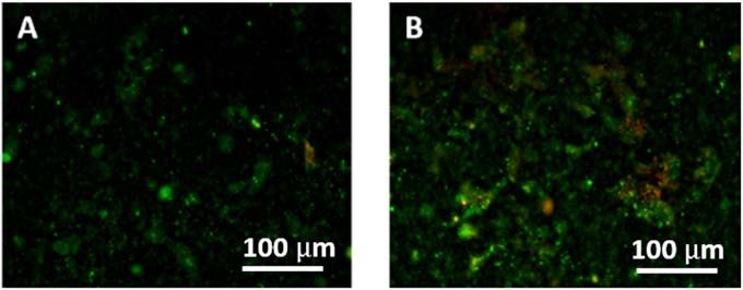
Mater. Res. Express 7 (2020) 025504                                                            https://doi.org/10.1088/2053-1591/ab6c99

                              PAPER

                              Stainless steel coated with carbon nanofiber/PDMS composite as
OPEN ACCESS
                              anodes in microbial fuel cells
RECEIVED
23 October 2019
                              Meriem Saadi1, Julien Pézard2, Naoufel Haddour2 , Mohsen Erouel1, Timothy M Vogel2 and
REVISED
5 January 2020
                              Kamel Khirouni1
                              1
                                  Laboratory of Physics of Materials and Nanomaterials Applied at Environment, Faculty of Sciences in Gabes, Gabes University, 6072,
ACCEPTED FOR PUBLICATION
16 January 2020                   Gabes, Tunisia
                              2
                                  Université de Lyon, Ecole Centrale de Lyon, UMR CNRS 5270, Ampère, F-69130 Ecully Cedex, France
PUBLISHED
4 February 2020               E-mail: naoufel.haddour@ec-lyon.fr

                              Keywords: microbial fuel cell, CNF-PDMS, stainless steel electrodes, biofilm, extracellular electron transfer
Original content from this
work may be used under
the terms of the Creative
Commons Attribution 4.0
licence.                      Abstract
Any further distribution of   Modification of electrode surfaces is a promising strategy to improve microbial fuel cell (MFC)
this work must maintain
attribution to the
                              performance. Here we report a new functionalization process to improve interfacial electron transfer,
author(s) and the title of    biocompatibility and corrosion resistance of stainless steel (SS) electrodes used as anodes in MFCs. SS
the work, journal citation
and DOI.                      anodes prepared by surface modification with a thin layer (200 μm) of conducting composite made of
                              polydimethylsiloxane (PDMS) doped with commercially available carbon nanofibers (CNF), are
                              described. Electrochemical characterization showed that the corrosion rate of SS electrode in an acid
                              solution decreased from 367 μm.y−1 to 31 μm.y−1 after CNF-PDMS coating. Electric characterization
                              demonstrated that the maximum power density generated by MFCs after 16 days with SS/CNF-
                              PDMS anodes (19 mW.m−2) is 5 times higher and more stable than that with unmodified SS (3.7
                              mW.m−2). The cyclic voltammetry analysis indicated that the electrochemical activity of the modified
                              anode was enhanced significantly after 16 days and the electron transfer was facilitated by CNF-PDMS
                              modification. Microscopic observations and electrochemical characterization showed that CNF-
                              PDMS composite improved biocompatibility and corrosion resistance of the SS anode surfaces. These
                              results confirmed that the CNF-PDMS modification is a promising approach to improve the
                              properties of anode materials for MFC application.

                              1. Introduction

                              Microbial fuel cells (MFCs) have been recognized as a promising technology for the direct conversion of organic
                              matter into electricity using bacterial biofilms as biocatalysts [1–3]. The possibility of producing electrical energy
                              from organic waste with this technology opens up perspectives for renewable energy recovery from sewage,
                              industrial effluents, and agricultural waste. Thus, this technology could have the dual advantage of producing
                              clean, sustainable energy and eliminate waste. However, the electricity production of MFCs remains too low for
                              their large-scale applications in wastewater treatment. These restrictions are mainly due to the slow kinetics of
                              electron transfer from bacteria to electrode surfaces at anode electrode [4]. The electroactive bacteria are able to
                              use the anode, which is made out of an electrically conductive material, as the final electron acceptor of their
                              anaerobic respiratory chain. Electrons are thus released to the anode and then travel to the cathode through an
                              external electrical circuit. The development of low cost and high performance anodes, is one of the key factors
                              for practical implementation of MFCs. Carbon materials in different forms (paper, cloths, foam, fibers, felt,
                              granulesK) are generally used as anode electrodes in MFCs [5–8]. These biocompatible materials are resistant to
                              corrosion but have low mechanical stability and low electrical conductivity [9, 10]. Since carbon materials offer
                              less electrical conductivity than pure metal, most material used for electrical connection of anodes to the
                              external circuit, are metallic (titanium, stainless steel or copper). Indeed, carbonaceous current collectors could
                              be a source of potential loss and a metallic collector plate is the best way to reduce electron travel distance and
                              contact resistance between electroactive bacteria and the external circuit [11]. Cheng et al showed power losses

                              © 2020 The Author(s). Published by IOP Publishing Ltd
Mater. Res. Express 7 (2020) 025504 M Saadi et al
and drop in potential distribution on the electrode surface arising from resistivity of carbon anode material and
current collector configurations [12]. Generally, corrosion of metal material limits their use as anode in MFC
application. SS has been proposed as alternative material for anode electrodes in MFCs due to its high
conductivity compared to carbonaceous materials [13]. However, SS electrodes used as anodes in MFCs suffer
from poor biocompatibility and corrosion fatigue [14, 15]. Several research groups have reported that SS surface
modification succeeded in improving biocompatibility and corrosion resistance of SS anodes, as well increasing
the power density produced by MFCs. Liang et al reported surface modification of SS electrodes by chemical
vapor growth of carbon coat, by electrodeposition of polyaniline polymer, by electrochemical grafting of neutral
red molecules and by heat treatment [16]. These studies showed the possibility of improving the power
generation of MFCs with SS anodes but their corrosion resistance performance was not reported. Pu et al
described electrochemical polymerization of polypyrrole on the surface of SS anodes [17]. Polypyrrole
modification improved corrosion resistance and biocompatibility for a better MFC performance. However,
some factors currently limit the applications of polypyrrole because of its low mechanical properties and low
processibility [18]. The aim of this work is to study a new modification method of SS anode surfaces with thin
layer (200 μm) of low-cost and mechanical stable CNF-PDMS composite. This new functionalization approach
improves interfacial electron transfer, biocompatibility and corrosion resistance of anode surfaces, and ensures a
homogenous potential distribution on the surface through the current collector configuration ‘large plate
metallic current collector’. In addition, the thin layer of CNF-PDMS carbon material reduces both travel
distance between electroactive bacteria and the current collector, and the potential drop arising from resistivity
of this carbon material. PDMS is a commercially available material with physically and chemically stable
properties [19]. PDMS is an attractive material to fabricate microfluidic structures and is widely used for lab-on-
a-chips. Recently, this elastomer was shown to be conductive after doping it with conducting nanoparticles and
nanotubes [20–22]. Carbon doped PDMS was used in microfluidic systems for heating [23], detection of
droplets [24], and electrochemical measurements [25]. However, the best of our knowledge, modification of SS
electrodes with conducting PDMS was never reported even though these layers could be deposited on large
electrode surfaces and at low costs.
2. Materials and methods
2.1. Electrode preparation
For CNF-PDMS preparation, we used a 10:1 (w/w) mixture of PDMS base and curing agent (Sylgard 182
Silicone Elastomer) that was degassed under vacuum. Carbon nanofibers (CNFs) with a diameter of 200 nm and
length of 50 μm (purchased from Sigma-Aldrich, >99.9% carbon basis) were reinforced in insulating polymer
(PDMS) at a weight ratio of 8:100 to prepare a conductive composite (CNF-PDMS). The mixture was
thoroughly mixed for 20 min by hand until obtaining a homogeneous paste. SS foil of 0.25 mm thick (AISI 316L
purchased from Goodfellow) was cut into square electrodes with dimensions of 1×1 cm. SS electrodes were
washed with acetone, ethanol and distilled water before using and then dried at room temperature. CNF-PDMS
past was then cast on SS electrode surfaces and the obtained layer was levelled to the height of pattern placed
around the electrode. SS modified electrodes were then cured 80 °C for 2 h. The thickness of the formed CNF-
PDMS layer on the flat surface of the electrodes was controlled using a mechanical profilometer (Veeco Dektak
3030) and was around 0.2 mm high.
2.2. Electrode characterization
The morphology of the CNF-PDMS layers was examined with a scanning electron microscope (SEM, JEOL
model JSM-7401 F). The resistivity of this material was determined by four-point measurements with a probe
station and a Keithley 4200 Source Measure Unit (SMU). The corrosion resistance was investigated by Tafel
curves using linear voltammetry in H2SO4 solution (0.1 M) at a scanning rate of 10 mV.s−1. A potentiostat OGS
100 from Origalys was used to perform electrochemical characterizations. The unmodified and modified SS
electrodes were used as working electrodes, a commercial saturated Ag/AgCl electrode as a reference and a Pt
wire electrode as an auxiliary electrode. The geometric surface area of unmodified and modified electrodes was
used for calculating both corrosion current density and power density of MFCs.
2.3. MFCs setup and operation
Single-chamber batch MFCs were set up in 250 ml Wheaton bottles realized by (Schott Duran, Germany) for
laboratory applications. The air cathodes were made of carbon cloth Fuel (Cell Earth,Woburn, USA). Then were
coated with PTFE and 5% of platinum catalyst as described by Cheng et al [26]. The cathode with a diameter of
2.3 cm was fixed by a clamp and silicone sealant on the aperture side of the bottle. Each anode was placed in the
2Mater. Res. Express 7 (2020) 025504 M Saadi et al
Table 1. The typical of PDMS composites doped with different carbon particles.
Polymer Conducting particles carbon %(w/w) Conductivity [S.m−1] References
PDMS Carbon nanotubes 10 100 [27]
PDMS Black carbon 8 0 [20]
PDMS Black carbon 25 10 [25]
PDMS Carbon nanofibers 8 80 This study
center of each bottle. Anode and cathode were placed on opposite sides of the reactors and connected to the
external circuit by titanium wires (Alfa Aesar, Karlsruhe, Germany).
2.4. Biofilm preparation
The MFCs were filled with 250 ml of primary effluent and 1.25 g (5 g l−1) of dehydrated sludge from a Grand
Lyon domestic wastewater treatment plant (Lyon, France) and fed with 0.25 g (1 g l−1) of sodium acetate (Roth,
Karlsruhe, Germany) as carbon source. All reactors were cultivated simultaneously at a stable ambient
temperature. An external resistance of 1000 Ω is connected to the electrodes in order to shuttle electrons from
the anode to the cathode.
2.5. MFCs operation
The MFC voltage was recorded every 5 min using an Agilent 34970 (a data acquisition instrument/Switch Unit)
with a precision of 1 μV. MFC electrical performances were determined by polarization curve analysis using
linear sweep voltammetry (LSV) technique. The LSV tests were carried out with potentiostat (origaflex 0GF01A,
France) by potential sweep from open circuit potential (OCP) of the MFC to 0 V at a scanning rate of 1 mV.s−1.
2.6. Biofilm characterization
The characterization of anodic biofilms was carried out by fluorescence microscopy. A LIVE/DEAD BacLight
Bacterial viability kit (Invitrogen) was used to label the samples. 1.5 μl of propidium iodide and an aliquot
(1.5 μl) of SYTO9 were mixed in 2 ml of sterile NaCl 0.8%. Thereafter, 200 μl were deposed on each sample of
anodic biofilm and incubated for 15 min in the dark before observations with Axio Imager Zeiss microscope.
The evolution of the biofilm electroactivity was measured 4 and 16 days after operation start by cyclic
voltammetry (CV) with a rate of 10 mV s−1 from −0.6V to 0.8V in a three electrode system. The anode was used
as the working electrode, the cathode as the auxiliary electrode and an Ag/AgCl electrode was used as the
reference electrode.
3. Results and discussion
3.1. Conductivity characterization of CNF-PDMS layers
Conductivity measurements showed that electrical resistance of CNF-PDMS layers saturated for samples
containing more 8% mass ratio of carbon nanofibers to PDMS. We were unable to increase the conductivity of
CNF-PDMS paste with higher carbon content because of mixing issues. For this ratio (8%), CNF-PDMS layers
provided efficient electrical properties with a conductivity of (80±1) S.m−1 (table 1). This conductivity value
was lower than the conductivity of carbon nanotubes/PDMS composites [27], but higher than that of the black
carbon/PDMS composites previously described [15, 20]. Despite the low mass ratio of carbon nanofibers, these
results show that CNFs were well dispersed in the PDMS matrix and preserved connections in the percolated
CNF networks. However, conductivity of 316 L SS unmodified foil (1.33×10⁶ S.m−1 according to supplier
data) is around 104 times greater than CNF-PDMS conductivity.
3.2. Electrode surface morphology of C-PDMS coated anode
EM images show that CNFs are well dispersed and randomly oriented on the surface of the polymer
(figure 1(A)). These results demonstrated that the deposition of CNF-PDMS on SS plate increases the effective
surface area of the electrode. The high magnification micrograph (figure 1(B)) shows that the diameter of single
nanofibers at the exit of the PDMS matrix is higher than the 200 nm indicated by the supplier. This part of the
fibers, is coated with PDMS, which must reduce their surface conductivity. This is attributed to the strong
linkage between nanofibers and polymer matrix that leads to a decoration of CNFs by polymer molecules.
However, we note that the diameter of nanofiber extremities is around 200 nm (figure 1(C)), which corresponds
to the value indicated by the supplier. This means that they are stripped and conductive. These comb-like
conducting structures on CNF-PDMS layers could facilitate the direct extracellular electron transfer (EET) of
3Mater. Res. Express 7 (2020) 025504 M Saadi et al
Figure 1. SEM images of CNF-PDMS layer.
electroactive bacteria (EAB) to the electrode. In direct EET, EAB (e.g., Geobacter sulfurreducens) can transfer
their electrons directly via conductive pili called nanowires [28].
3.3. Anti-corrosion performance of C-PDMS coated anode
The Tafel curves of the unmodified and modified SS electrodes indicated that the corrosion potential increased
from −113 mV to 232 mV and the corrosion current decreased from 2.1 mA.cm−2 to 0.17 mA.cm−2 after CNF-
PDMS deposition on SS surfaces (figure 2). The decrease of corrosion current and the rise of the positive
corrosion potential were consistent with a better anti-corrosion performance. The corrosion resistance of CNF-
PDMS/SS electrodes was better than that of bare SS electrodes and the corrosion rate of SS electrode decreased
from 367 μm.y−1 to 31 μm.y−1 after CNF-PDMS coating. These results ensure that CNF-PDMS layers have an
anti-corrosion effect by preventing the direct contact between SS surface and solutions.
3.4. Electricity production performance
The MFC voltage was recorded as function of time during a month in order to follow the biofilm formation on
anode surfaces. The voltage of MFC with unmodified SS anode increased rapidly on the 5th day of the
experiment (5 days after inoculation of MFCs with primary effluent and domestic wastewater) reaching 0.26 V
(figure 3).
The voltage of MFC with CNF-PDMS/SS anode progressively increased after a week and reached the same
value after two weeks. These results indicate that the biofilm grows less well on the surface CNF-PDMS anode
than that of unmodified SS anode. The startup time of MFC with CNF-PDMS anodes, was probably increased by
the non-conductive part of the surface (PDMS) which is hydrophobic. Indeed, Santoro et al reported that
hydrophobic surfaces slowed down the biofilm attachment and made the start-up period of MFCs longer [29].
Therefore, it possible that this long start up period for CNF-PDMS surfaces is the result of the harder biofilm
formation on this material.
4Mater. Res. Express 7 (2020) 025504 M Saadi et al
Figure 2. Tafel curves of unmodified SS electrode (gray curve) and CNF-PDMS/SS electrode (black curve).
Figure 3. Voltage as a function of time of MFC with unmodified SS anode (gray curve) and with CNF-PDMS/SS anode (black curve).
Figure 4. Polarization curves of MFC with unmodified SS anode on the 4th day (gray dashed curve) and 16th day (gray solid curve) of
the experiment. Polarization curves of MFC with with CNF-PDMS/SS anode on the 4th day (black dashed curves) and 16th day (black
solid curves) of the experiment.
The maximal power density of MFCs was measured at different times in order to compare the electroactivity
of biofilms (figure 4). After 4 days, the maximal power density of MFC with unmodified SS anode (35 mW.m−2)
was almost twice as high as the maximal power density of MFC with CNF-PDMS/SS anode (16 mW.m−2). This
difference was probably due to the low conducting area of CNF-PDMS layers. The surface of this conductive
polymer is composed in a large part of insulation and about 10% of conductive surface, unlike unmodified SS
anodes where the entire surface is conducting. Although the conductive area of this composite surface only
5Mater. Res. Express 7 (2020) 025504 M Saadi et al
Figure 5. (A) Cyclic voltammetry at 10 mV.s−1 of unmodified SS anode (gray curve) and CNF-PDMS/SS anode (black curve) on the
4th day of the experiment. (B) Cyclic voltammetry at 10 mV.s−1 of unmodified SS anode (gray curve) and CNF-PDMS/SS anode
(black curve) on the 16th day of the experiment.
corresponds to about 10% of its geometric surface and is almost 10 times smaller than the area of unmodified SS
surface, the maximum power density produced is only 2 times lower. The conducting CNFs enhanced EET
transfer between EAB and composite anode. After 16 days, polarization curves showed a decrease in the maximal
power density of MFC with unmodified SS anode to 3.7mW.m−2, while the maximal power density of MFC with
CNF-PDMS/SS anodes increased slightly to 19mW.m−2. The decrease in the power performance of unmodified
SS anodes was due to the poor biocompatibility and corrosion fatigue of this material. The stability of the
electrical performances of the modified anodes demonstrated that CNF-PDMS layers improved the
biocompatibility and corrosion resistance of SS anode surfaces.
3.5. Characterization of active biofilm
Cyclic voltammograms of MFC anodes were recorded on 4th and 16th days of the experiment (figure 5). After
four days, cyclic voltammogram of unmodified SS anode exhibited a small faradaic peak centered at −400 mV
versus Ag/AgCl and a higher one at 40 mV versus Ag/AgCl. The observed peaks correspond to two different
modes of EET and to two life-style modes inside electroactive biofilms. One group, represented by Shewanella
oneidensis, capable of using a large range of electron acceptors and substrates and able to mediate indirect EET,
and another group, represented by Geobacter sulfurreducens, capable of using a small range of electron acceptors
and substrates and able to mediate direct EET. Based on previously reported values, the negative potential region
corresponded to mediated electron transfer of Shewanella oneidensis and/or heterogeneous electron transfer of
Geobacter sulfurreducens EAB [30, 31]. At positive potentials, the direct electron transfer was the major EET
mechanism [32]. Cyclic voltammogram of CNF-PDMS/SS anode on the 4th day, showed a low electroactive
activity with a small Faradaic peak in the high positive potential region (400 mV versus Ag/AgCl). After sixteen
days, the electrochemical response of the unmodified SS anode did not change much with a decrease in the
intensity of the redox peak in the negative potential region. However, catalytic electroactivity CNF-PDMS/SS
anode greatly increased and had two intense peaks in both positive and negative potential regions. These results
indicated that after biofilm growth, CNF-PDMS layer improved both the biofilm formation and the EET of EAB
on the surface of SS electrodes.
6Mater. Res. Express 7 (2020) 025504 M Saadi et al
Figure 6. Anodic biofilms observed in fluorescence microscopy using a focus x100 on (A) unmodified SS electrode and (B) CNF-
PDMS modified electrode. Biofilms were labelled using a LIVE/DEAD Bactlight viability kit. Dead bacteria with damaged membrane
are red, whereas living bacteria with an undamaged membrane are green.
After a month of biofilm growth, the characterization of MFC anodes by fluorescence microscopy showed
that the surface of CNF-PDMS/SS electrodes was loaded with a higher coverage percentage of biofilm on a
modified surface area than that observed on the unmodified SS electrodes (figure 6). These results indicate that
CNF-PDMS layers improved biocompatibility of SS surfaces and the growth of biofilms on this material.
4. Conclusion
Coating of SS anodes with CNF-PDMS layers for MFC application improves the stability of the electrodes for
long term power generation. The comb-like conducting structures on CNF-PDMS layers facilitated the direct
EET of EAB to the electrode. However, CNF-PDMS coating increase start up period of MFCs probably due to
hydrophobic properties of PDMS. The changes in surface characteristics of CNF-PDMS material could improve
the interaction between material and bacteria and accelerate biofilm formation. Besides, CNF-PDMS coating
had an anti-corrosion effect and enhanced biocompatibility of SS surfaces. This modification method is a
promising approach to improve properties of anode materials for MFC application.
Acknowledgments
This work was financially supported by the ‘PHC Utique’ program of the French Ministry of Foreign Affairs and
Ministry of higher education, research and innovation and the Tunisian Ministry of higher education and
scientific research in the CMCU project number 19MAG23.
ORCID iDs
Naoufel Haddour https://orcid.org/0000-0002-2430-5568
References
[1] Rabaey K and Keller J 2008 Water Sci. Technol. 57 655–9
[2] Qiao Y, Bao S J and Li C M 2010 Energy Environ. Sci. 3 544–53
[3] Li M et al 2018 Biotechnol. Adv. 36 1316–27
[4] Logan B E, Murano C, Scott K, Gray N D and Head I M 2005 Water Res. 39 942–52
[5] Wei J, Liang P and Huang X 2011 Bioresour. Technol. 102 9335–44
[6] Cai H, Wang J, Bu Y and Zhong Q 2013 J. Chem. Technol. Biotechnol. 88 623–8
[7] Senthilkumar N, Pannipara M, Al-Sehemi A G and Gnana Kumar G 2019 New J. Chem. 43 7743–50
[8] Yang C et al 2019 Sci. China Mater. 62 645–52
[9] Zhou M, Chi M, Luo J, He H and Jin T 2011 J. Power Sources 196 4427–35
[10] Guo K, Prévoteau A, Patil S A and Rabaey K 2015 Curr. Opin. Biotech. 33 149–56
[11] Liu H, Cheng S, Huang L and Logan B E 2008 J. Power Sources 179 274–9
[12] Cheng S, Ye Y, Ding W and Pan B 2014 J. Power Sources 248 931–8
[13] Guerrini E et al 2014 J. Electrochem. Soc. 161 H62–7
[14] Chen Y et al 2012 J. Power Sources 201 136–41
[15] Mansfeld F and Little B 1991 Corrosion Science 32 247–72
[16] Liang Y et al 2017 J. Power Sources 342 98–104
[17] Pu K B et al 2018 Biochem. Eng. J. 132 255–61
[18] Ben Slimane A, Chehimi M M and Vaulay M J 2004 Colloid Polym. Sci. 282 314–23
[19] Bergveld P, Lötters J C, Olthuis W and Veltink P H 1997 J. Micromechanics Microengineering 7 145
[20] Niu X Z, Peng S L, Liu L Y, Wen W J and Sheng P 2007 Adv. Mater. 19 2682–6
[21] Cong H and Pan T 2008 Adv. Funct. Mater. 18 1912–21
7Mater. Res. Express 7 (2020) 025504 M Saadi et al
[22] Khosla A and Gray B L 2009 Mater. Lett. 63 1203–6
[23] Gong X and Wen W 2009 Biomicrofluidics 3 012007-14
[24] Niu X, Zhang M, Peng S, Wen W and Sheng P 2007 Biomicrofluidics 1 1–12
[25] Brun M, Chateaux J F, Deman A L, Pittet P and Ferrigno R 2011 Electroanalysis 23 321–4
[26] Cheng S, Liu H and Logan B E 2006 Electrochem. Commun. 8 489–94
[27] Chu K et al 2013 IEEE Electron Device Lett. 34 668–70
[28] Reguera G et al 2006 Appl. Environ. Microbiol. 72 7345–8
[29] Santoro C et al 2014 Carbon N. Y. 67 128–39
[30] Roy J N, Babanova S, Garcia K E, Cornejo J, Ista L K, Atanassov P et al 2014 Electrochimica Acta 126 3–10
[31] Katuri K P, Rengaraj S, Kavanagh P, O’Flaherty V and Leech D 2012 Langmuir 28 7904–13
[32] Pinto D, Coradin T and Laberty-Robert C 2018 Bioelectrochemistry 120 1–9
8You can also read