B-Box RCP 3.0 CONTROL PLATFORM - THE ULTIMATE SOLUTION FOR FAST AND RELIABLE DEVELOPMENT AND TESTING - imperix
←
→
Page content transcription
If your browser does not render page correctly, please read the page content below
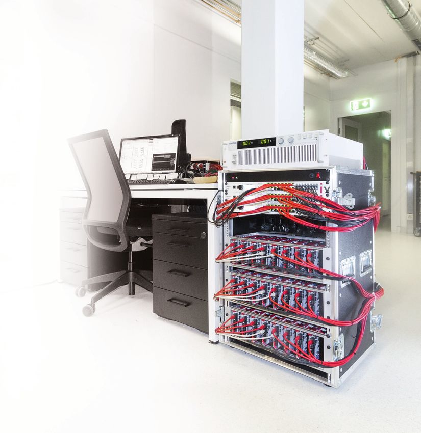
B-Box RCP                       3.0

CONTROL PLATFORM

The B-Box RCP accelerates the development
and experimental validation of converter control
techniques in a laboratory environment.

           THE ULTIMATE SOLUTION FOR FAST AND
            RELIABLE DEVELOPMENT AND TESTING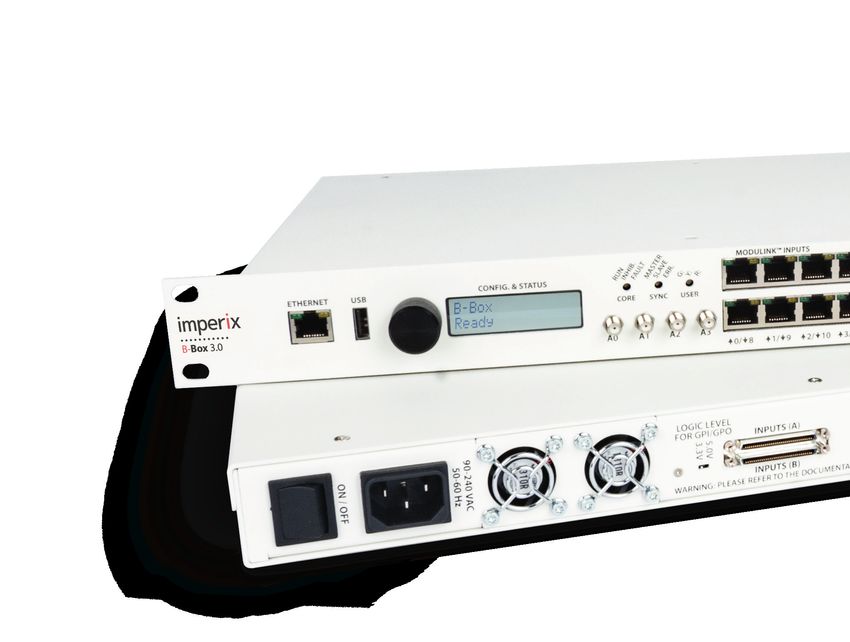
ANALOG OUTPUTS
                                                                       4 channels
                                                                       ± 5V full-scale outputs
                                                                       Real-time configurable from
                                                                       the BB Control utility software

                                               ELECTRICAL INPUTS
                                                 Connector A                                  Connector B
                                                  8x General Purpose Inputs (GPI 0-7)          8x General Purpose Inputs (GPI 8-15)
                                                  16x Fault inputs (e.g. driver feedback)      36x User-configurable I/0s
                                                  1x SPI/I2C link

TAILORED DESIGN                                                        HIGH-END DESIGN
The B-Box RCP is entirely and exclusively tailored to be a rapid       B-Box RCP embeds the latest processing devices, including a
prototyping controller. It notably distinghuishes by the very high     dual-core ARM processor and Kintex-grade FPGA.
flexibility of its analog front-end and specialized I/O interfaces.    Together with an ultra-light and specialized operating system,
Also, B-Box RCP has been designed for synchronous sampling             this guarantees state-of-the-art performance for all closed-loop
applications and a strict management of timings, from analog           control applications. Running a converter control algorithm in
inputs to PWM outputs, including in stacked configurations.            the hundreds of kHz range becomes no longer a challenge!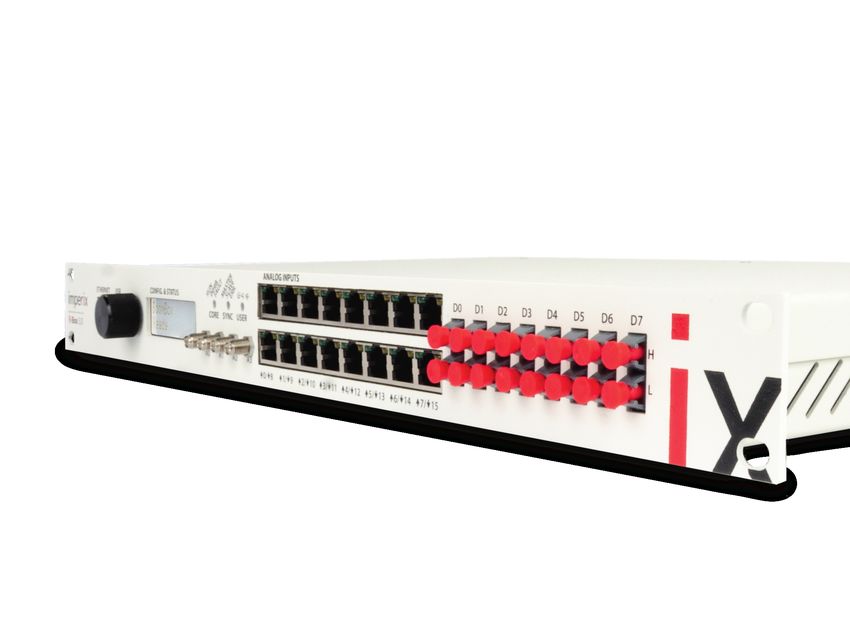
ANALOG INPUTS
        16 channels
        ± 10V full-scale inputs
        High-Z full diff. or Low-Z single-ended
        Programmable gains
        Programmable low-pass filters (+ bypass)

                                                          OPTICAL OUTPUTS
                                                             16x PWM outputs (PWM 0-15)
                                                             Rigorous pairs or independent signals
                                                             Plastic optical fiber (650um)

                                                              SFP+ INTERCONNECT
                                                                 I/O extension for inter-B-Box communication
                                                                 5 Gbps RealSync™ link
                INTERLOCK
                   Inter-systems shared fault line
                   Electrical and optical signalling

ELECTRICAL OUTPUTS
 Connector C                                           Connector D
  8x General Purpose Outputs (GPO 0-7)                  8x General Purpose Outputs (GPO 8-15)
  16x PWM outputs (PWM 0-15)                            16x PWM outputs (PWM 16-31)

SCALABLE DESIGN                                                       FUTURE-PROOF DESIGN
Multiple B-Box units can be stacked together to build up larger       The B-Box RCP is built over a strong hardware abstraction layer,
controllers. Up to 64 boxes can be combined, extending up to          which guarantees the stability of its operation – as a platform –
thousands of I/Os!                                                    over time and accross the evolution of its own hardware.
This brings high flexibility in time and accross multiple projects.   This way, it is guaranteed that a code that works today will still
It is always possible to combine (or separate) units depending on     work in the future, even though the hardware will most certainly
the varying needs of their applications.                              have changed in-between.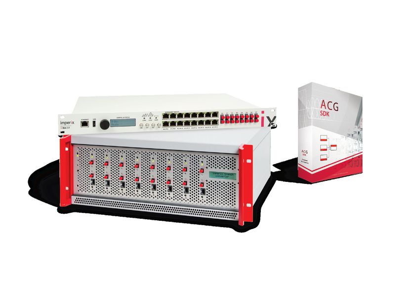
KEY SPECIFICATIONS
                                NEW                                          NEW                                          MORE
    2x ARM 1Ghz                DSP             4 ns PWM resolution         FPGA                134 user I/Os              I/OS

 System on chip            Zynq XC7Z030-3                   x1       User I/Os                 Electrical (3.3V)               x36
 Processor                 ARM Cortex A9 1Ghz               x2       (high-speed)              (bi-directional)
                           1GB DDR3                                  General-purpose I/Os      IN, electrical (3.3V / 5.0V)    x16
 FPGAs                     Kintex 7 125K (main)             x1                                 OUT, electrical (3.3V / 5.0V)   x16
                           Artix 7 35T (auxiliary)          x1
                                                                     Fault inputs              Electrical interlock             x1
 Analog inputs             16bits @ 500ksps                x16                                 Optical interlock                x1
 Encoder inputs            3pins (A,B,Z), shared with DI    x2                                 Digital inputs (shared)         x16
 PWM outputs               Optical                         x16       Communication             Ethernet 1 Gbps (RJ45)           x1
                           Electrical (3.3V)               x32                                 SFP+ 5 Gbps                      x3

BENEFITS
                                                                    SWITCH FROM SIMULATION TO
                                                                    EXPERIMENTATION IN NO TIME
                                                                    The B-Box RCP can be programmed in just one click directly from
                                                                    Simulink™. Besides, everything can be accurately simulated first,
                                                                    ensuring that everything that works in simulation also works in
                                                                    the real world!

GO EARLY TO THE LAB AND WORK
STRAIGHT AHEAD WITH POWER
With the hardware protections present in the B-Box RCP, engineers
can start testing early and confront their models to real-world
issues as soon as possible.

                                                                    GENERATE HIGH QUALITY AND
                                                                    IMPACTFUL EXPERIMENTAL RESULTS
                                                                    Thanks to the data logger embedded in the B-Box RCP, every signal
                                                                    can be observed, tuned and logged during run time. This allows to
                                                                    generate high quality measurements in the blink of an eye.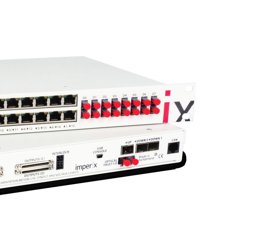
DEVICE & OPERATION

PROGRAMMING                                    EXECUTING                                     MONITORING
The B-Box RCP has been designed to be          B-Box RCP can be used alongside a com-        The BB Control utility software is the tool
easily programmed using C/C++ code or          puter or as a standalone device.              for the real time access to B-Box RCP and
using automated code generation toolbox        In both cases, a Gigabit Ethernet connec-     B-Board PRO controllers. It enables users
for Simulink™.                                 tion provides a programming access and        to access, monitor and tune any variable
All it takes to flash a control code on the    a direct insight into the code's execution,   in real time.
B-Box RCP is one click; code generation,       thanks to the BB Control utility software.    This software also provides datalogging
compilation and upload on the device are       This way, B-Box RCP an be used as a desk-     capabilities that are comparable to those
fully automated.                               top-based development platform, as well       of an oscilloscope combined with a sig-
Besides, no particular skills are needed to    as an integrated controller within a larger   nal generator. This allows to produce and
program the B-Box RCP; complete block-         system. This second scenario may be of        observe various transient regimes, while
set and code libraries are readily available   interest in microgrids, where the focus is    logging every data point, thereby facili-
to make programming as easy as possible.       rather put on strategy-level aspects.         tating the tuning of control parameters.
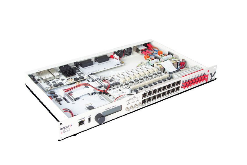
WHAT'S INSIDE
        Each B-Box RCP features no less than 2 FPGAs, a dual-core
        processor and several microcontrollers, enabling state-of-
        the-art performance and an unrivaled ease of use!

1 PROCESSING BOARD                             2 FRONT DISPLAY                                  3 AUXILIARY FPGA
A high-performance embeddable                  A direct access to all details and set-         The necessary hidden logic behind
controller at the heart of B-Box RCP.          tings from the front panel.                     a highly flexible platform.
The B-Box RCP embeds a high-performance        All configuration settings for the analog       The Artix 7 FPGA located on the mother-
variant of B-Board PRO controller. It there-   front-end can be directly modified from         board hosts all of the resident features of
fore ideally supports the very demanding       the LCD front panel. Status message are         the B-Box RCP such as protection, signal
needs of rapid control prototyping.            also immediately made available.                mapping and internal monitoring.

                                                                  4
                                                                         DIO       DIO         DIO      DIO

                                 ZynQ                      3
                                                            Artix
                  1

                                                       ADC                               ADC
                              MCU                                                                          5
                                                        Configurable                       Configurable
                                                      analog front-end                   analog front-end
                          2
               ETH        USB        LCD               LED        AIN                    DAC         AIN               POF
                                                                                                                   6

4 ELECTRICAL I/Os                              5 ANALOG FRONT-END                               6 OPTICAL I/Os
High-performance I/Os for                      A fully-configurable front-end                  Plug-and-play compatibility with
demanding control applications.                within a power converter controller.            imperix power modules.
B-Box RCP offers hundreds of digital I/Os.     With configurable impedance, gains and          With superior EMC performance, optical
Furthermore, thanks to their direct ties to    low-pass filter frequencies, the B-Box RCP is   fibers are the preferred solution for con-
FPGA logic, ultra-fast operation is possible   ready to accommodate any analog signal,         veying PWM signals, which are also 100%
with a bandwidth above 200 Mbps.               with no additional interface board.             plug-and-play with power modules.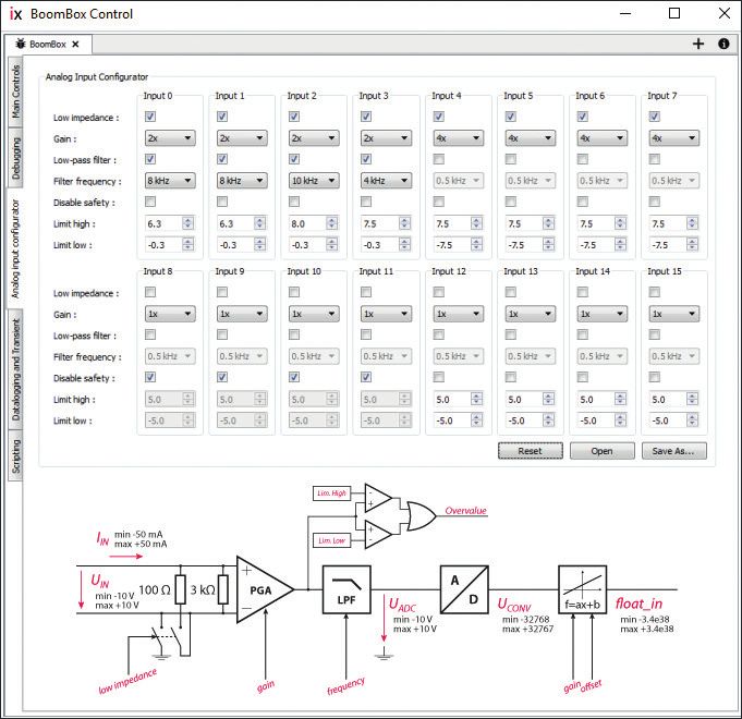
KEY FEATURES
                                  CPU

                                                                     USER-PROGRAMMABLE FPGA
                               imperix IP
                                                                     Absolutely no expertise in FPGA-based development is needed
                                                                     to work with the B-Box RCP, as it operates readily with a highly
                                                                     flexible and highly configurable FPGA firmware.
    ADC                         user IP         PWM                  Nevertheless, for those who require to implement specialized
                                                                     control logic inside the FPGA, a dedicated area is provided, with
                                                                     straightforward integration within the DSP software kernel.
                                FPGA

HIGH PROCESSING POWER
The B-Box RCP uses a 1 GHz dual-core processor. One core is ded-
icated to the closed-loop control tasks (bare metal, dedicated
kernel), the other one to the supervision and monitoring (linux).
Besides, most low-level tasks are shifted in FPGA.
This results in the complete dedication of a fast floating-point
processor core to real time control tasks, with best-in-class per-
formance, ranging up to 250 kHz closed-loop control frequencies.

                  High limit
                                                                     HARDWARE-LEVEL PROTECTION
    Measurement

                                                                     In case of dangerous operating conditions, the B-Box RCP
                                                                     instantly blocks all its PWM signals, thanks to a dedicated hard-
                  Low limit                                          ware protection circuit. This guarantees a high level of protection,
                                                                     entirely independently from both the DSP cores and the FPGA.
FAULT                                                                The B-Box RCP is also self-protected against inappropriate software
PWMH                                                                 conditions such as excessive computational burden or critical algo-
PWML                                                                 rithmic errors.

                                                                                                            Prot. Limit High   -
                                                                                                                               +           Overvalue

HIGHLY FLEXIBLE FRONT-END                                                                                   Prot. Limit Low
                                                                                                                               +
                                                                                                                               -
                                                                             IIN
Each B-Box RCP possesses 16 highly configurable analog inputs.
                                                                      UIN                                                          A
This obviates the burden of repeatedly developing analog                              100 Ω   3kΩ   PGA
                                                                                                               LPF                     D       f=ax+b
signal conditioning interfaces for each project.                                   anc
                                                                                      e
                                                                            imp
                                                                                ed
                                                                                                     gain          ncy                         gain
                                                                      low                                   freque

Each input channel features:
   3 kΩ full-differential voltage-type input or 100 Ω single-ended
   current-type input
   Programmable safety thresholds
   Programmable gain amplifier and low-pass filter
A HARDWARE FOR POWER ELECTRONICS
Tailored peripherals for best-in-class performance and convenience
READY FOR ANY SENSOR
Highly flexible analog front-end
The B-Box distinguishes from other RCP platforms by
its highly configurable and high-performance front-
end. This allows to easily adapt to existing prototypes
and/or allow to switch easily across several projects.
Characteristic Setting Value Unit Feature Available settings
Input impedance High-Z 3.00 kΩ Input format High-impedance, full differential
Low-Z 100.0 Ω Low-impedance, single ended
CMRR > 72 dB Programmable gains G = 1, 2, 4, 8
Signal-to-noise ratio (SNR) > 88 dB Low-pass filter FCUT = 500 Hz – 40 kHz
Accuracy (pre-calibration) 0.5 % No filter (physical bypass)
USB USB
CPU1CPU1
CANCAN
BBOSBBOS
ETH ETH
LPF LPF ADCADC x16 x16
low-Zlow-Z
high-Z
high-Z PGAPGA ADCADC
0.5–400.5–40
kHz kHz 16b / 500
16b kS
/ 500 kS
GPI GPI
USR USRCLK CLK OCMOCM
safetysafety
threshold
threshold
ENC ENC
master
master
overvalue
overvalue SFP+SFP+
switch
switch
safetysafety
threshold
threshold
SFP+SFP+
SFP+SFP+
ANALOG FRONT- END DSP+FPGA
PROCESSING
S TO P
READY FOR ANY MISTAKE
Software-independent protections
Each analog input channel features programmable safety
thresholds which allow to block the generation of PWM
signals in less than 1 μs in case of an overvalue (e.g. over-
voltage or overcurrent). READY FOR EXPANSION
This mechanism is implemented at the hardware level, so Transparent I/O extension
that it is entirely independent from the operation of both B-Box RCP can be used in stacked configurations up
the CPU and the FPGA. It is hence guaranteed to be effec- to 64 units. Communication uses 5 Gbps optical fibers
tive even when the user application is still under debug- and the RealSync™ technology, which simultaneously
ging and not sufficiently reliable on its own. guarantees an extremely low latency and extremely
high synchronization accuracy (see later). Moreover,
this is absolutely transparent to the user so that noth-
ing needs to be configured at any point in time. Slave
I/Os simply work as if they belonged to the master.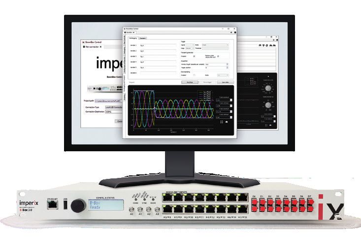
READY FOR WIDE BANDGAP SEMICONDUCTORS
                                                                    High performance modulators

                 CB-PWM                                             The newest B-Box RCP hardware supports a ultra-high time resolution of 4 ns
                                                                    (250 Mhz) on all its PWM signal generation processes. This guarantees a high angular
                                                                    resolution even in very fast-switching applications such as with Silicon Carbide (SiC)
                                                                    semiconductors.
                                                                    Very-low jitter on all PWM signals is also guaranteed such that the overall temporal
                                                                    accuracy of all edges is also maintained up to the gate drivers. This way, very low
                                                                    dead times (typ. < 50ns) can be configured, hence minimizing distortion sources in
                                                                    very fast switching applications.
                                                                    What's more, this is also guaranteed across several B-Boxes, thanks to the imperix
                                                                    RealSync™ technology!
                PWM_OUT
                                                                                                   Characteristic                        Min.    Typ.   Max.    Unit
                                                                                                   Resolution                                    16             bits
                                                                                                   Operating frequency range             0.001          2'500   kHz
                         x32                                                                       (with 1 % angular resolution)
                                                                                                   Output jitter/skew (single B-Box)             ±4.5   ±13     ns

                                                                                          SS-PWM                     (accross B-Boxes)           ±6.5   ±15     ns

N_TYPE

            CPU0CPU0                                                                                            x16 x16
            linuxlinux

                                                                   x32 x32
                                PWMPWM
                                           dead time

                                                       dead time

         CELL_RISE                                                           overvalue
                                                                                  overvalue

                DDR3
                   DDR3
ter                                                                     LUT       2N x PWM_OUT
                                GPOGPO
                                   CELL_STATES                                   overvalue
                                                                                      overvalue
         CELL_FALL
                                DACDAC
                datadata                                                                                        x32 x32
               logger
                   logger       LED LED

                                                                                 PWM OUTPUTS

                                                                                                                                    READY FOR ANY PROJECT
                                          READY FOR ANY
                                                                                                                                    Multiple I/O expansion options
                                          MODULATION ALGORITM
                                                                                                                                    By default, B-Box RCP is designed to
                                          Pre-implemented modulators                                                                operate with RJ45 analog inputs and
                         x32       x4     B-Box RCP supports a broad range of PWM                                                   fiber optical outputs. This is what is
                                          techniques, thanks to dedicated modulators                                                directly plug-and-play with imperix
                 CB-PWM        SV-PWM
                                          that are pre-implemented inside the FPGA.                                                 power modules.
                                          This guarantees a safe and sound behavior                                                 Furthermore, numerous electrical I/Os
                          x4       x2     and relieves users from the burden of imple-                                              are also available for other projects or
                  PP-PWM       SS-PWM     menting and testing their own peripherals.                                                interfacing additional equipment. Fast
                                          By default, B-Box RCP provides carrier-based                                              bidirectional I/Os are also available for
                                          and space-vector modulators, programmed                                                   custom-implemented FPGA firmware.
                         x32       x1     pulse patterns (e.g. for selective harmonic
                 DO-PWM        SB-PWM     elimination), direct output access (e.g. for
                     1                    model-predictive control) and sort-and-
                                          select balancing and modulation for Modular
                                          Multilevel Converters (MMC).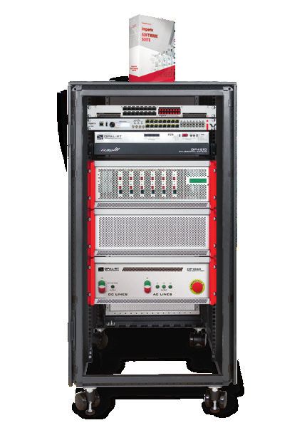
PROGRAMMING
Software Development Kits (SDK)

        1 C L I CMKIN G
               M
     PROGR A

ACG SDK                                                                 C/C++ SDK
The Automated Code Generation (ACG) SDK enables engineers               The C/C++ SDK provides a direct way to implement converter
to program B-Box RCP and B-Board PRO controllers directly from          control techniques without requiring any simulation software.
MATLAB™ Simulink™. The provided toolchain handles fully auto-           This approach also offers superior performance and flexibility
mated code generation, compilation and upload, in just one click.       over automatically-generated code.
In addition, the SDK contains simulation models of each control-        The SDK contains extensive libraries, specifically developed to
ler peripheral, so that the exact system behavior can be simu-          make the coding experience as simple as possible, while grant-
lated – and hence easily anticipated – before code is generated.        ing users direct access to each and every system parameter.

                    ACG SDK             C/C++ SDK
                                                                         FEATURE                                         ACG SDK           C/C++ SDK
                    OPERATING SYSTEM                                     BBOS operating system
                                BB OS                                    Blockset for Simulink™ *
                    UTILITY SOFTWARE                                     C/C++ coding environment
                            BB Control                                   BB Control monitoring software
                                                                         Code examples
                   Simulink TM           C/C ++
                     BLOCKSET                                            User-editable FPGA area
                                                                         Multi B-Box operation (I/O extension)
               Operating system
                                      = ACG SDK                          * Requires a valid MATLAB™ license issued by MathWorks™ and the following toolboxes :
               + Simulink™ blockset *                                      Embedded Coder, MATLAB™ Coder and Simulink™ Coder.
               Operating system       = C/C++ SDK

MULTIPLE HARDWARE                                 OPEN FRAMEWORK                                     SOFTWARE FOR EVERYONE
The very same software can be used for            Imperix SDKs beeing only a set of tools,           Irrespectively of the level of expertise or
programming either the B-Box RCP or the           engineers remain in complete control of            field of use, the very same software can
B-Board PRO. Besides, thanks to the strict        their control software. Everything can be          be used for teaching purposes, R&D activ-
equivalence between both devices, user-           tuned or edited down to the duty cycle!            ities or industrial applications. Everything
level control software is also guaranteed         Furthermore, the FPGA firmware can also            is kept simple, allowing to accelerate any
to behave identically.                            be modified for even more flexibility.             development.
MONITORING
BB Control utility software
REAL TIME MONITORING AND TUNING
With the BB Control utility software, the execution of the control
code can be fully supervised from a PC. The software allows to
both visualize and modify any variable in real-time. It is then the
perfect tool for the easy debugging of any control algorithm.
What’s more, thanks to the full dedication of a separate CPU core
for the data logging, the monitoring and tuning and logging of
variables is guaranteed not to interfere with the real-time execu-
tion of the main control code.
DATA LOGGING AND PROCESSING
The datalogging capabilities of B-Box RCP and B-Board PRO are
directly accessible from the BB Control utility, allowing to see
exactly what the code sees and does at every sample. The latest
hardware enhancements enable access to 32 channels of 50'000 pts.
The datalogging can oberve any variable and can be triggered
from any signal, offering maximum flexibility. Also, thanks to the
associated transient generator, testing the transient response of
control loops and tuning them has never been so easy!
FRONTPANEL CONFIGURATION
Each of the 16 analog inputs channels of the B-Box RCP can be
configured visually, directly from within the BB Control utility.
This way, all hardware parameters can be stored together with
other software and recalled instantly when moving to the lab.
This also enables several users to share the same control hard-
ware and carry with them their individual configurations.SOLUTIONS FOR THE INDUSTRY
From the lab to the field!
BRIDGE THE GAP BETWEEN PROTOTYPES AND PRODUCTS!
What if you could simply take the result of your
research and put it into an affordable controller,
directly embeded inside your own products?
DEVELOPMENT PHASE PRODUCTION PHASE
Flexible hardware Cost-optimized hardware
Rapid control validation Pre-validated control
FULL BITFILE COMPATIBILITY!
B-Board PRO
Embeddable controller
B-Box RCP
Prototyping controller
The exact compatibility between B-Box RCP
and B-Board PRO allows to benefit from the
increased flexibility of the prototyping con-
troller during developments, while using
a lower-cost product-embeddable variant
during series production.
BITFILE COMPATIBILITY SMALL FORM FACTOR PROCESSING POWER
The FPGA-based abstraction layer present Despite its numerous I/Os, the B-board The 3rd generation of controllers rely on
in B-Box RCP and B-Board PRO guarantees measures only 86x124 mm. It is therefore dual-core processors and modern FPGAs
the exact same performance (especially small enough to be mounted within most for best overall performance in demanding
timings) on both devices. industrial control systems. applications.HIGH-END INTERCONNECT
Imperix RealSync™ technology
PERFECT SYNCHRONIZATION Master B-Box RCP controller
Imperix’s patent-pending RealSync™ technology guarantees
an unrivaled synchronization accuracy across multiple units,
down to ± 2.0 ns! This is achieved through advanced clock
dissemination through the optical fibers, enabling multiple
SFP fiber
B-Boxes to operate as if they were one single unit!
Slave B-Box RCP controller
HIGH-SPEED COMMUNICATION
The 5 Gbps SFP+ links can be configured to form a tree-
shaped network, achieving superior data bandwidth and
lower latency over daisy-chain or ring topologies. This guar-
antees sub-microsecond data transfers in many configura- Slave B-Box RCP controller
tions with up to 8 controllers!
MAXIMUM I/O CAPABILITIES
Component Single (1 unit) Stacked (64 units)
400 4
Analog inputs 16x 1024x
Number of measurements
350 3.5
300 PWM outputs Optical
3 16x3rd B-Box 1024x
2nd B-Box
Latency [μs]
250 Electrical
2.5 32x 2048x
200 2
General-Purpose digital Outputs (GPO) 16x 1024x
150 1.5
General-Purpose digital Inputs (GPI) 16x 1024x
100 1 2nd B-Box
50 0.5
0 0
-2 -1.5 -1 -0.5 0 0.5 1 1.5 2 0 16 32 48 64 80 96
Synchronization error [ns] Number of channels
ADC read PWM (duty) PWM (duty+phase)
400 400 4 4
Number of measurements
Number of measurements
350 350 3.5 3.5
300 300 3 3 3rd B-Box 3rd B-Box
2nd B-Box 2nd B-Box
Latency [μs]
Latency [μs]
250 250 2.5 2.5
200 200 2 2
150 150 1.5 1.5
100 100 1 1 2nd B-Box 2nd B-Box
50 50 0.5 0.5
0 0 0 0
-2 -1.5 -1-2 -0.5
-1.5 0 -1 0.5
-0.5 1 0 1.5
0.5 2 1 1.5 2 0 16 0 32 16 48 32 64 48 80 64 96 80 96
Synchronization
Synchronization
error [ns] error [ns] Number ofNumber
channels
of channels
ADC read ADCPWM
read(duty) PWM PWM
(duty)(duty+phase)
PWM (duty+phase)
The synchronization bet ween B -Boxes is Ultra-low latency is achieved even with a high
achieved without the user even knowing it! number of ADC or PWM channels. This allows
The guaranteed accuracy is ± 2.0 ns. closed-loop control frequencies up to 250 kHz.POWER ELECTRONICS PROTOTYPING
PLUG-AND-PLAY SOLUTIONS
By combining imperix control and power hardware with dedicated
software and accessories, users benefit from a broad range of pro-
totyping equipment, suitable for everyone’s need and ambition.
2
Power converter
Real power circuits
3
1 Sensors
B-Box RCP + Software Voltage & current
Real time controller
Optical fibers
Analog signals (RJ45 cables)
2
STARTER KITS
DEVELOP AND BUILD UP
SYSTEM PROTOTYPES WITHIN MINUTES!
OUR HARDWARE
+
3x
Combined together, imperix products are ideally suited for
laboratory and teaching applications. They indeed possess
all the features – ranging from ease-of-use to robustness – 3
to be safely put in the hands of engeneers and even students. 3
Starting kits and specialized bundles are now available on
imperix.ch/products/bundles, which allow to start working
in the the lab straight away, with almost no start up time. 1 SV–PWM
YOUR IDEAS
abc abc abc
dq dq dq
Udc*
INTEGRATION LEVELS PI
Iq* PI
Imperix products can be delivered as bare and independent
products, fully turnkey systems, or anything in-between.
POWER RATINGS ACCESSORIES
Imperix products are well suited for the implementation of Imperix provides several accessories that also contribute to facil-
power converter prototypes ranging from 100 W to 100 kW. itate the implementation of laboratory-scale converters.
INTER-OPERABILITY SOFTWARE EXAMPLES
Imperix products are plug-and-play when used together, but Imperix is currently building a complete knowledge base of control
can also be used with any other controller or power stage. code and software examples, available free of use.cb
a
BUNDLES EXAMPLES
a b c
a
w u
u
e
d
submodule
inductor
arm
In order to accelerate as much as possible the prototyping of power converters, imperix
c
provides several bundles including hardware, software and all the necessary
v accessories c b
to start working as soon as products are delivered.
v
w c
b
a
MF
d a
d
d
c
arm
a
submodule
inductor
a a
a b
b a c b
c
c
b
b
e b
e
LIGHT MMC BUNDLE MICROGRID TEST BENCH
REACH WORLD-CLASS RESULTS IN NO TIME! EXPERIMENT IN THE REAL WORLD!
The MMC bundle is a typical example of a ready-to-use system. The microgrid test bench is a multi-purpose test bench for
Dedicated to Modular Multilevel Converters it allows engineers power electronics. It is able to support both HIL simulation and
to focus on converter control techniques rather than hardware low-voltage experimentation with an easy-to-use reconfigurable
implementation. hardware.
* HARDWARE + SOFTWARE * HARDWARE + SOFTWARE
3x B-Box RCP B-Box RCP
Software ACG SDK and BB Control utility Software C/C++ SDK and BB Control utility
3x open chassis with 24 x PEH 2015 Interface for Opal-RT simulators
4x voltage sensors Opal-RT OP4510 HIL
6x inductors Converter box with 6x PEB 8032
Passives and filters box
OPTIONS
Grid connection box
Simulink™ blockset
VARIANTS OPTIONS
PEB modules for more power Simulink™ blockset
6x B-Box RCP + 6x racks VARIANTS
Other simulator
Power amplifier for PHIL
* All current prices are available on www.imperix.ch10 0 419 imperix Ltd. Rue de la Dixence 10 CH-1950 Sion Switzerland Phone +41 (0)27 552 06 60 Fax +41 (0)27 552 06 69 www.imperix.ch sales@imperix.ch Find your closest distributor on imperix.ch/resellers
You can also read