Storm User's Manual for the Bolt - Food & Feed Analysis
←
→
Page content transcription
If your browser does not render page correctly, please read the page content below
QA RELEASED

Storm User’s Manual
   for the Bolt®
Contents
1. Introduction ............................................................................................................................... 3
1.1. Intended Use ................................................................................................................................. 3
1.2. Certifications ................................................................................................................................. 3
2. Safety Information...................................................................................................................... 3
2.1. General Safety ............................................................................................................................... 3
2.2. Electrical Safety ............................................................................................................................. 4
2.3. Mechanical Safety ......................................................................................................................... 4
2.4. Biological Safety ............................................................................................................................ 4
2.5. Safety Labels ................................................................................................................................. 4
3. System Description ..................................................................................................................... 4
3.1. System ........................................................................................................................................... 5
3.2. System Details ............................................................................................................................... 5
3.3. Component Details ....................................................................................................................... 6
4. Storm System Software .............................................................................................................. 8
4.1. Storm System Configuration Options ........................................................................................... 8
4.2. Storm Server and Storm Configuration Tool Components ........................................................... 9
4.3. Storm Instrument Manager ........................................................................................................ 13
4.4. Other Software Applications ....................................................................................................... 17
5. Running a Worklist ................................................................................................................... 17
5.1. Worklist Preparation ................................................................................................................... 17
5.2. Racks Tab..................................................................................................................................... 21
5.3. Microtiter Plates Tab................................................................................................................... 22
5.4. Worklist Tab ................................................................................................................................ 23
5.5. Worklist Completion ................................................................................................................... 24
6. Evaluation and Search Tabs....................................................................................................... 24
6.1. Evaluation Tab............................................................................................................................. 24
6.2. Search Tab ................................................................................................................................... 26
7. Tools Tab .................................................................................................................................. 26
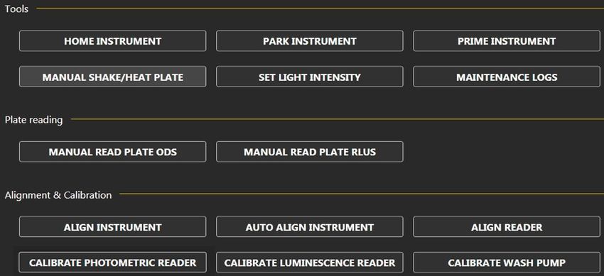
7.1. Tools ............................................................................................................................................ 26
7.2. Plate Reading .............................................................................................................................. 27
7.3. Alignment and Calibration .......................................................................................................... 27
8. Maintenance ............................................................................................................................ 31
8.1. Daily Maintenance ...................................................................................................................... 31
8.2. Weekly Maintenance .................................................................................................................. 31
8.3. Periodic Maintenance ................................................................................................................. 32
8.4. Storage, Transportation, and Disposal........................................................................................ 32
9. Laboratory Information System Integration ............................................................................... 32
9.1. LIS Records .................................................................................................................................. 33
9.2. LIS Query and Transmission Examples ........................................................................................ 34
9.3. LIS Configuration ......................................................................................................................... 35
9.4. RS-232 Pin Layout ....................................................................................................................... 36
10. Troubleshooting Guide ............................................................................................................. 37
11. Contact Information ................................................................................................................. 41
11.1. Device Manufacturer .......................................................................................................... 41
11.2. Authorized Representative ................................................................................................. 41
BOLT-0006.D 10/04/2017 Page 2 of 41
1. Introduction
The purpose of this manual is to identify the instrument components and provide instructions for use of
the Bolt Instrument. This manual provides basic safety information, instructions for use and maintenance,
as well as general troubleshooting guidance. It is recommended that this manual be kept near the
instrument and accessible to the user at all times.
Note: All references to CLIA (Chemiluminescent Immunoassay), luminescence, or RLU (Relative Light
Units) measurement are only available for use with Bolt instruments equipped with the
chemiluminescence option.

    1.1.      Intended Use
    The Bolt is designed to automate the processing of enzyme immunoassay (EIA) and Chemiluminescent
    Immunoassay (CLIA) tests. The system is only intended to be used by properly trained personnel.
    The intended use for the Bolt is as a discrete photometric chemistry analyzer intended to duplicate
    manual analytical procedures by performing various steps such as pipetting, heating, and measuring
    color intensity automatically. The Bolt is also intended to perform as an ‘accessory’ to be used with a
    device to enable that device to be used in accordance with its intended purpose.

    1.2.      Certifications
    The Bolt is registered and certified as having met the following regulatory requirements: 13485:2003
    EN ISO 13485:2012
    Directive EN 98/79/EC
    EN 61010-1:2010
    EN 61010-2-081:2002 + A1:2003
    CMDR SOR/98-282
    21 CFR

2. Safety Information
The following safety instructions are to be observed at all times during the operation of the Bolt. It is
strongly recommended that all first time personnel read this manual prior to working with the instrument
and receive training from Gold Standard Diagnostics (GSD) or a GSD distributor.
The Bolt is designed and manufactured in accordance with the safety requirements for electronic and
medical systems listed in the certifications section above to ensure that the instrument functions safely,
both electrically and mechanically under normal use conditions. The Bolt is supplied in a condition that
allows for safe and reliable operation.

    2.1.      General Safety
    The Bolt must only be operated in accordance with the stated intended use. It is recommended that
    the Bolt is used only with the spare parts and accessories suggested or provided by Gold Standard
    Diagnostics. The use and maintenance activities defined in this manual are intended to ensure the
    safety of the operator and the proper functionality of the instrument. All system surfaces must be
    dry while operating the Bolt. Gold Standard Diagnostics recommends that all operators be trained in
    good laboratory practices and observe general laboratory safety guidelines.

BOLT-0006.D                               10/04/2017                                           Page 3 of 41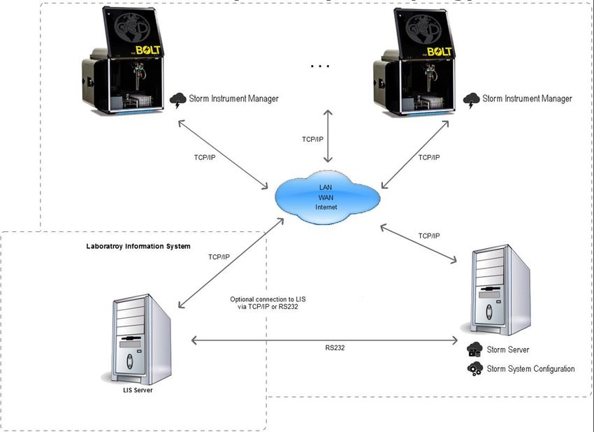
2.2. Electrical Safety
The Bolt must be operated using a power source with an operating voltage compatible with the
requirements stated on the device label. The Bolt is to be used only with the provided 3-prong
grounding type plug to connect the instrument to the main power supply. It is important to ensure
the power switch is in the ‘Off’ position prior to connecting the Bolt to the main power supply.
The use of a multi plug is not allowed and it is recommended that the instrument be run from a
dedicated socket connected to an uninterruptible power supply or surge protector. Use only
extension cables with a protective conductor and grounded contact. The Bolt uses two fuses, one AC
fuse (part number 5015) and one DC fuse (part number 5383). Fuses that are non-functioning must
be replaced using fuses which match the values (nominal voltage, nominal current, and type) specified
for the instrument. A spare AC fuse is included with the instrument. If at any time the instrument
becomes unsafe to use, immediately switch it off and disconnect it from the main power supply.
2.3. Mechanical Safety
Installation and service of the Bolt is completed by a trained technician to ensure a minimized
exposure of the operator to mechanical risks. Improper handling of the Bolt may cause serious
damage to the instrument or result in injury to the user. Avoid touching the probe and other moving
parts while the system is in operation. Protective covers should not be removed while the instrument
is on due to potential contact with moving parts. Exercise extreme caution when working on or near
the peristaltic pump when the cover is not in place. Openings provided for ventilation are not meant
as access points into the system.
If the cover must be opened during operation, verify that the movement of the probe has stopped
before reaching inside the instrument. This should be done cautiously and only when absolutely
necessary.
2.4. Biological Safety
Any parts of the Bolt that have come into contact with samples/test reagents are to be treated as
being potentially infectious. Some of the general purpose reagents have the potential to cause
irritation of the skin and mucous membranes. It is recommended that the operator use appropriate
personal protective equipment (PPE) such as gloves, lab coat, and eye protection while using the
instrument. For devices used in conjunction with the Bolt, it is the responsibility of the user to observe
the instructions and warnings provided by the manufacturer for proper use of reagents.
2.5. Safety Labels
The Bolt is labeled with universal general warning labels to identify risks which may be encountered
by the operator.
3. System Description
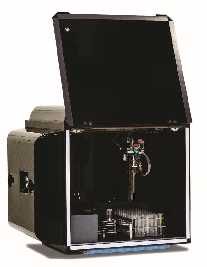
The Bolt is a fully automated microtiter plate processor that is able to completely perform sample
processing steps, including dilutions, dispenses, incubations, shaking, and wash processes. The Bolt also
provides photometric and luminescent measurement and evaluation. The Bolt is controlled by a Windows
PC software program that is specifically designed for the system.
Note: Due to the modular nature of the Bolt, some features/components may not be available on all
instrument models.
BOLT-0006.D 10/04/2017 Page 4 of 41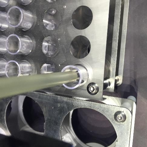
3.1.       System
   The Bolt system consists of a robotic platform that performs programmed EIA and CLIA tests and a
   Laptop PC with software that enables automated running of assay steps, worklist generation, data
   management, and data reduction.

    The system components are as follows:

          1    System Cover

          2    Reagent Rack

          3    Sample Rack

          4    Microtiter Plate Carrier

          5    Probe Assembly

   3.2.       System Details
   It is recommended that the area for use and storage of the Bolt be a space dedicated to the instrument
   which is able to accommodate the following specifications. For optimum instrument performance,
   the room temperature should be controlled at temperatures between 20°C and 24°C (68°F to 75.2°F),
   the relative humidity should be between 20% and 90% (non-condensing), and the environment should
   be relatively dust-free and free of excessive vibration.
   Instrument Power Specifications
   Voltage: 100 – 265 V
   Frequency: 50 – 60 Hz
   Power Consumption: 12W without incubator, 120W max
   It is recommended that the instrument be operated off of a dedicated power source. Ideally the Bolt
   should be placed near an outlet and connected to a surge protector or an uninterruptable power
   supply (UPS).
   Instrument Dimensions and Weight
   Width: 48.3 cm (19 in)
   Depth: 53.3 cm (21 in)
   Height: 55.8 cm (22in)
   Weight: 27 kg (60 lb.)
   The total bench space recommended to accommodate the Bolt and related equipment is 127 cm (50
   in.) wide x 88.9 cm (35 in.) high x 60cm (23.6 in.) deep. The laboratory bench must be sturdy enough

BOLT-0006.D                               10/04/2017                                         Page 5 of 41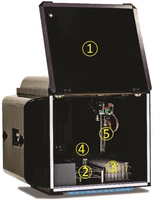
to support the full weight of the Bolt as well as additional equipment. Expect the total weight of the
   Bolt and accessory equipment to be approximately 50 kg (110 lbs.).

   3.3.       Component Details
   Note: Certain instrument models may not contain all of these components.
   Sample Racks
   The removable stainless steel rack is available in various interchangeable sizes to accommodate 12,
   13 or 16mm diameter sample tubes (up to 100mm in height). The 12mm and 13mm racks can
   accommodate up to 96 patient samples, while the 16mm rack can hold up to 72 patient samples.
   Custom racks are also available. Sample tube positions are numbered beginning in the back left
   corner of the rack and proceeding left to right across each row, from back to front.
   Reagent Rack
   The reagent rack contains 9 reagent positions and accepts 22 to 35mm diameter bottles (reagent
   adapters are required). Custom reagent adapters are also available.
   Microtiter Plate Carrier
   The microtiter plate carrier contains one reaction microtiter plate position (left plate position) and
   one pre-dilution plate position (right plate position).
   Probe Assembly
   The Bolt utilizes a single probe, dual needle system; no disposable tips are used. This system is capable
   of precise pickups and dispenses for volumes between 1ul and 300ul. The high-precision micro-
   syringe aspirates 1ul with less than 3% CV across a 96-well plate (as part of 1:100 dilution). Liquid
   detection is performed via conductivity, with a minimum detection volume of 50ul.
   Incubator
   The incubator heats to a maximum of 45°C.
   Reader
   The Bolt’s on-board reader is an ultra-compact, fully integrated LED spectrophotometer which
   contains the standard wavelengths of 405, 450, 490, 550 and 630 nm. Custom wavelengths are also
   available.
   Photometric range: 0 to 3.0 OD
   Spectral range: 400 nm to 700 nm
   Read time: approx. 2min/plate
   Precision: 0 to 2.000 OD: +-0.003 OD or CV < 1%, 2.001 OD to 3.000 OD: CV < 1.5%
   Resolution: 0.001 OD
   Linearity: < 1% 0 to 2.000 OD (typical), < 2% 2.001 OD to 3.000 OD
   Instruments equipped with the chemiluminescence option also contain a chemiluminescence reader
   and can handle both EIA and CLIA assays.
   Detection Type: glow
   Spectral Range: 300nm-500nm
   Dark Count: 50 counts per second (standard)
   Measuring time: 100ms (adjustable 100-1000ms)
   Dynamic range: 6 decades (orders of magnitude)
   Shaker

BOLT-0006.D                              10/04/2017                                             Page 6 of 41
The integrated linear shaker features a no-spill design. The Bolt can incubate while the shaker is in
   motion.
   Amplitude: 0.6 mm
   Adjustable speed: up to 900 RPMs
   Capacity: 2 MTP (1 reaction, 1 predilution)
   Voltage: 5 V DC
   Computer
   The computer is attached to the instrument via a USB connection. The computer also
   contains Ethernet, RS232, and additional USB ports.
   Computer specifications are listed below:
   The instrument computer (in a single or multiple instrument environment) must meet the following
   minimum specifications:
   Processor: Intel Celeron 1.6 GHz
   Memory (RAM): 4 GB (32-bit) or 8 GB (64-bit)
   Memory (Hard Disk): 120 GB
   Ports: USB 2.0 (RS232, Ethernet ports optional)
   Display: DirectX 11 graphics device with WDDM 1.2 driver, 1366x768 resolution
   Operating System: Windows 8 (Windows 10 recommended)
   .NET Framework: .NET 4.5
   If running in a multiple instrument environment with a separate server computer, the server
   computer (with the Storm Server and Storm System Configuration Tool) must meet the following
   specifications, depending on the number of instruments connected to the server:
                                              Memory
            # of                    Memory                                          Operating         .NET
                       Processor               (Hard        Ports     Display
       Instruments                   (RAM)                                            System      Framework
                                                Disk)
                          Intel                                     DirectX 11
              1         Celeron     4.00 GB    120GB       USB 2.0    graphics
                        1.6 GHz                            (RS232, device with Win 8 (Win 10
                                                                                                    .NET 4.5
                      Intel i3 2.0                        Ethernet WDDM 1.2 recommended)
              5                     8.00 GB    240GB
                          GHz                               ports      driver,
                      Intel i5 2.5                        optional) 1366x768
             10                     8.00 GB    500GB
                          GHz                                        resolution

   Software
   The pre-installed Storm System Software runs on the Windows based computer included with the
   instrument. It provides the ability to create and run Worklists, analyze results from Worklist runs,
   generate reports of Worklist results, and integrates with any LIS that supports the NCCLS LIS1-A and
   LIS2-A specifications.
   The Storm System Software is highly configurable and includes support for audible alerts for various
   events that occur during the use of the instrument. Computer speakers should be enabled at all
   times and additional speakers are recommended.
   The Storm System Software is described in detail in the following sections of this manual.

BOLT-0006.D                             10/04/2017                                          Page 7 of 41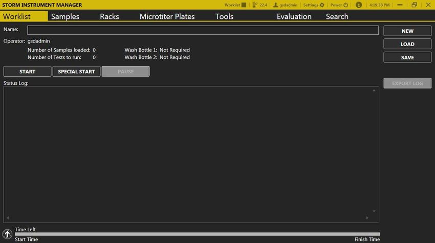
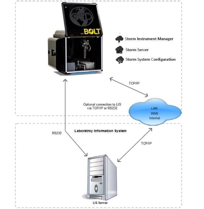
4. Storm System Software
The Storm System Software is required in order to operate the instrument and is comprised of three
components: the Storm Server, the Storm System Configuration Tool, and the Storm Instrument
Manager.
The Storm Server is a process that responds to requests from one or more Storm Instrument Manager
instances to provide management of data generated from Worklist runs. The Storm Server also stores
system configuration information shared by all Storm Instrument Manager instances connected to the
server.
The Storm System Configuration Tool is used to configure settings for the Storm System; the Storm
System Configuration Tool is used to configure settings that are common to all Storm Instrument
Manager instances connected to the Storm Server. The Storm System Configuration Tool must always be
installed on the same computer on which the Storm Server is running.
The Storm Instrument Manager allows the user to select, configure, and run ELISA and CLIA assays for a
given set of Samples on the instrument. These configurations are saved and run as Worklists. The Storm
Instrument Manager also allows the user to evaluate the results of Worklist runs, as well as perform
instrument maintenance.
All software components are pre-installed on the computer included with the instrument. Note: Gold
Standard Diagnostics periodically provides software updates to distributors and customers. This manual
describes the current version of software. Contact the local instrument distributor with any further
questions about software versions or software update instructions.

   4.1.       Storm System Configuration Options
   There are two ways in which the Storm System Software can be configured:

   1. Single Instrument Configuration (default):
   For labs with a single instrument, or a small number of instruments which will not be run together as
   a system, the Single Instrument Configuration can be used. In this configuration, all three
   components of the Storm System Software are installed and run on a single instrument computer,
   as shown in the following diagram:

BOLT-0006.D                             10/04/2017                                          Page 8 of 41
2. Multiple Instrument/Central Server Configuration:
   For labs with multiple instruments, it is recommended that the Storm Server be installed and run on
   a central computer that is connected via a TCP/IP network to each instrument computer running the
   Storm Instrument Manager. This configuration is shown in the following diagram:

   The central, shared Storm Server allows for a common configuration of all Storm Instrument
   Managers and a single connection to the LIS.
   If using the Central Server Configuration, contact the local instrument distributor for additional
   instructions regarding software installation on the central server computer and proper configuration
   of all software components.

   4.2.       Storm Server and Storm Configuration Tool Components
   The Storm Server is a Windows Service that runs in the background of the computer on which it is
   installed. The Storm Server service stores configuration data for the Storm System and processes
   requests from Storm Instrument Manager instance(s) to store and retrieve data generated from
   Worklist runs performed on the associated instrument(s).
   The Storm System Configuration Tool is used to specify configuration settings for the Storm System.
   These settings are stored by the Storm Server and used by all Storm Instrument Manager instances
   connected to the server. The Storm System Configuration Tool must be installed on the same
   computer on which the Storm Server service is running. The Storm System Configuration Tool can be
   utilized as follows:
   Storm System Configuration Tool Access
   To launch the Storm System Configuration Tool, double click/tap the associated icon on the desktop.
   Choose Yes if asked to allow the program to make changes to the computer. The Storm System
   Configuration Tool will prompt the user to choose a Storm System User Account to log in to the Storm
   System. Only users with Administrator accounts are allowed to configure the Storm System. Select

BOLT-0006.D                             10/04/2017                                          Page 9 of 41
desired user account (only users with Administrator accounts appear in list), enter the password on
   the login screen as prompted, and click/tap OK:

   Note: If an Administrator user forgets his/her password, a new password may be set using the Forgot
   Password button and following the subsequent instructions which appear on the screen.
   The Storm System Configuration Tool will then open:

   Storm System Configuration Tool Settings
   The settings selected in the Storm Configuration Tool, as described below, apply to all Storm
   Instrument Manager instances that are connected to the Storm Server in which these settings are
   stored. The following tabs are available in the Storm Configuration Tool software:
   1. Users: Use this tab to add and edit Storm System user accounts. These user accounts are used to
      log in to the Storm System Configuration Tool and to the Storm Instrument Manager instance(s)
      connected to the corresponding Storm Server in which these settings are stored.
           a. To add a user: Click/tap Add User. Enter User Name and Password, and Email Address
               (optional) as indicated. Activate the user by selecting the Active User option. Allow
               administrator rights for the user (if desired) by selecting the Administrator option.
               Otherwise, select the Operator option. Click/tap OK to save changes.
           b. To edit a user: Select desired user from the list and click/tap Edit User. Edit user
               information and settings as desired, then click/tap OK.
                    i. User accounts cannot be deleted, but can be deactivated by deselecting the
                       Active User option in the Edit User window. Deactivated users will not be listed
                       on login screens for the Storm software applications.
           c. User Account Types: There are two types of user accounts: Operator accounts and
               Administrator accounts.
                    i. Operator accounts are intended for the normal users of the Storm Instrument
                       Manager and its associated instrument(s). They can perform instrument
                       maintenance and create Worklists and run them on the instrument(s).
                   ii. Administrator accounts are intended for users with extra privileges. Users with
                       Administrator accounts can perform all tasks that users with Operator accounts
                       can perform, as well as other tasks which users with normal Operator accounts
                       cannot perform. Only Administrator users can log in to/change settings in the
                       Storm System Configuration Tool and access the Settings screen in the Storm
                       Instrument Manager. Other tasks reserved for Administrator users include:
                       marking worklists as reviewed, modifying worklist reports, and sending results
                       to the LIS. At least one Administrator account must always be active.
   2. Tests: The selected test files will be available to run in Worklists by the Storm Instrument Manager
      instance(s) connected to the Storm Server in which these settings are stored. Test files define all

BOLT-0006.D                              10/04/2017                                          Page 10 of 41
of the reagents, layout, action steps, and calculations for a given assay kit. Test files can be added
to and removed from the Storm System, and organized into folders (nodes).
a. To add Nodes: To add a grouping or node of tests, click the Add Node button. Enter the
desired node name as prompted and click OK. Multiple nodes can be added to
organize/group tests.
b. To add Tests: To add test(s) to the Storm system, first, copy/paste any test files which
will be added into a folder that is accessible by the computer running the Storm Server
and Storm Configuration Tool. The suggested/default file location is
C:\Users\Public\Documents\Storm\Tests.
To add tests to the main Root folder or to a previously defined node, select the desired
location, and click/tap the Add Tests button. Select test file type:
Then select desired test file(s) using the navigation panel on the left and highlighting the
files on the right. Multiple files can be selected using the CTRL or SHIFT keys:
After selecting desired file(s), click/tap the Open button.
The Refresh button can be used to refresh the selected file location and the Cancel
button can be used to cancel test addition.
Once added, nodes and tests will appear on the Tests tab:
c. To Remove Nodes/Tests: To remove nodes or tests, highlight the test(s) or node(s) to be
removed and click the Remove Test or Remove Node button, as appropriate.
3. Reports: Customize worklist report and test report information on this tab, as desired. First,
copy/paste any custom templates/logos into a folder that is accessible by the computer running
the Server and Configuration Tool. Use the “…” buttons to select custom template(s)/logo and
use the red X buttons to restore default settings. Default report templates and GSD logo will be
used on worklist reports if no changes are made.
a. To Customize Worklist Report: Select a custom report template, if required (most users
use default template). Select to order strips test reports by test, if desired (strips test
reports will be ordered by Sample ID by default).
Enter the name and address of the lab as it will appear on worklist and search reports
generated by the connected Storm Instrument Manager(s). Upload a logo if desired:
BOLT-0006.D 10/04/2017 Page 11 of 41Laboratory name, address, and logo can be exported to an .xml file and later imported,
if the same information should be used in multiple instrument systems, using the Import
and Export buttons.
b. To Customize Test Reports: Select different custom report templates for each test, if
required. Default EIA and STRIPS report templates remain selected by most users:
Contact the local instrument distributor if additional information about custom report
options is required.
4. LIS: Check to enable Laboratory Information System (LIS) communication, if system is connected
to an LIS. Check to enable LIS logging, if desired, and select desired log level. Select which LIS
connection type will be used (RS-232 or TCP/IP) and set port/server settings as applicable:
Be sure that all settings match those of the LIS system being connected. Click/tap Save LIS
Configuration to save changes or Discard Changes to remove changes. This tab must be
completed before LIS communication can be attempted from within the Storm Instrument
Manager.
5. LIS Mappings: Map each test name to the LIS Name and click/tap Save LIS Mappings to save
changes or Discard Changes to remove changes.
BOLT-0006.D 10/04/2017 Page 12 of 41An LIS name is seldom the real test name, but often a shorter one. It could also be a number or
code, depending on the laboratory policy. Be sure to enter LIS Names (often referred to as test
codes) exactly according to the laboratory’s LIS configuration.
6. Backup/Restore: Select the Backup or Restore button to backup or restore server database (with
all worklist report information/results) as desired or as required by the laboratory.
7. Archive/Purge: Archive, unarchive, and purge data as required by computer storage capacity or
laboratory regulations.
a. To Archive/Unarchive: Select desired date from before which to archive worklist data
from the database. If desired, select date after which to unarchive previously archived
data. Only worklists which are not archived are available for viewing on the Evaluation
and Search tabs of the connected Storm Instrument Manager(s).
b. To Purge: Select desired date from before which to purge worklist data from the database.
Once worklist data has been purged, it cannot be recovered.
Close the Configuration window using the X in the top right corner. If necessary, the Storm Server will
automatically be restarted to apply the changes specified in the Storm Configuration Tool settings.
4.3. Storm Instrument Manager
The Storm Instrument Manager enables the running of test files that are installed on the Storm
system. The instrument must be attached to a computer on which the Storm Instrument Manager is
installed in order to be operational. The interface for the Storm Instrument Manager is designed
with a title bar and tabs:
Title Bar →
Tabs →
Storm Instrument Manager Modes
The Storm Instrument Manager can be run in two modes:
1. Full Functionality Mode: This mode enables the running of Worklists and evaluation of test
results. In this mode, the instrument is powered on when the software is started (all tabs shown
above are available).
BOLT-0006.D 10/04/2017 Page 13 of 412. Evaluation Only Mode: This mode allows for data evaluation without Worklist running
functionality. The instrument is not powered on when the software is run in this mode (Only
Evaluation and Search tabs are available).
Note: If using the Multiple Instrument/Central Server Configuration, contact the instrument
distributor for additional instructions for installation of the Storm Instrument Manager on the central
server computer to be used in Evaluation Only mode.
Storm Document Folder
All relevant data related to the Storm Instrument Manager is located in the Storm documents folder:
C:\Users\Public\Documents\Storm
These folders and files can be accessed at any time, including when software applications are in use.
1. Errors: Errors that are encountered during use of the instrument are named by the date and
time at which they occur and stored in the Errors subfolder as text files:
2. Maintenance Reports: Records of users’ performance of all prompted maintenance actions are
stored (one file per month) in the Maintenance Reports subfolder in portable document format
(PDF), as shown here:
3. Report Templates: Any custom worklist or test report templates (if applicable) should be stored
in the Report Templates subfolder.
4. Status Log Files: The status (worklist action) logs from each worklist are automatically saved as
text files, named with the worklist name and status (completed, stopped, etc.), and organized
BOLT-0006.D 10/04/2017 Page 14 of 41into folders for each month, in the Status Log Files subfolder:
5. Tests: Test files should be stored in the Tests subfolder. Note: Test files must be added using
the Tests tab in the Storm Configuration Tool before they will be available in the Storm
Instrument Manager, even if they are stored in the Tests subfolder. When a test file is added to
the Storm Server using the Storm System Configuration Tool, a copy of the test file is stored in
the Storm Server Database. Changes to the original test file saved in the Tests subfolder will not
be recognized by the Storm System until the test file is re-added to the Storm System using the
Storm System Configuration Tool.
6. Worklist Export TSV/XLSX: Worklist reports exported from the Evaluation tab of the Storm
Instrument Manager as tab separated value (.tsv) files and excel (.xlsx) files are stored by default
in the Worklist Export TSV and Worklist Export XLSX subfolders, respectively.
7. Worklists: Worklists are automatically saved, named with the worklist name, and organized into
folders for each month, in the Worklists subfolder. These can be opened from within the Storm
Instrument Manager using the Load button on the Worklist tab.
Storm Instrument Manager Initialization
1. Verify that computer with installed Storm Instrument Manager is attached to the instrument,
system is connected to a computer with Storm Server and Storm Configuration Tool, power is
connected to instrument and to computer(s), and instrument power button is in the on position.
Turn on attached computer and double click/tap the Storm Instrument Manager (Full
Functionality Mode) icon (if Storm Instrument Manager does not initialize automatically at
computer startup) to initialize the system. Login screen will appear:
2. Select a user (only active users are displayed for selection), click/tap Log On, enter password,
and click/tap OK.
Note: If a user with an Operator account forgets his/her password, a user with an Administrator
account can reset the password using the Storm System Configuration Tool. If an Administrator
user forgets his/her password, a new password may be set using the Forgot Password button
and following the subsequent instructions.
3. After login is complete, the instrument requires approximately 30 seconds to automatically move
to its starting, or “home” position. The instrument must always be allowed to complete this
“homing” uninterrupted before being used:
BOLT-0006.D 10/04/2017 Page 15 of 41After homing, the Storm Instrument Manager opens.
Note: Whenever the Storm Instrument Manager opens, user is prompted to perform daily
startup maintenance, as well as weekly maintenance (if due). User must address each
maintenance prompt before continuing.
Storm Instrument Manager Title Bar
The following are displayed/accessible in the Storm Instrument Manager Title Bar:
1. Worklist State Icon: Indicates whether instrument is currently running a worklist or if the
instrument is idle/stopped.
2. Temperature Displays: The thermometer icon displays the internal temperature of the
instrument. If/when the incubator is turned on during the running of a worklist, temperatures of
the left/ right MTP position(s) is/are also displayed.
3. Current User: Displays the user ID of the logged in user. Logged in user can be changed by
selecting this icon and selecting Switch User. Password of the current user can also be changed
by selecting the Change Password option here and entering old and new passwords as indicated.
4. Settings: Used to select various software options, described in detail below.
5. Power: Used to close the software and shut down the instrument/computer. (Daily shutdown
maintenance will be prompted).
6. Application Version Information: Displays the version of the software/license information.
7. User’s Manual: Displays a PDF of the instrument User’s manual.
8. Current Computer Time: Displays the current time as set by the attached computer.
9. Minimize/Maximize: Used to minimize/maximize the Storm Instrument Manager main window.
10. Close: Used to close the software without shutting down the instrument/computer. (Daily
shutdown maintenance will be prompted).
*Note: Label/information about each icon is shown when hovering over each one.
Storm Instrument Manager Settings
Clicking/tapping the Settings icon on the Title Bar brings up the Settings window, used to adjust
various settings for running the Storm Instrument Manager (these settings can only be adjusted by
users with Administrator accounts):
1. Instrument Information: Displays instrument and reader details, including serial number and
runtime.
2. Samples: Aspiration Failure options allow user to decide what actions will be taken by the
instrument when insufficient sample volume is detected. User can choose to automatically
continue with the next sample or ask the operator for every low-volume sample.
Incubation setting allows implementation of an optional warning if the incubator is out of range
of the programmed temperature during a Worklist run (if incubator is used in the Worklist).
3. Worklist: Allows user to select whether or not tests with different timing schemes should be
allowed to run together. If tests with different timing schemes are allowed, user must select
whether the shortest or longest tests should be run first in the Worklist.
4. Strips: For monotest/strips assays, user can select the number of foil puncture retries, as well as
whether to automatically continue with the next sample or ask the operator for each strip when
the foil cannot be punctured. User can also choose to auto-skip strips after timeout/set number
of seconds.
BOLT-0006.D 10/04/2017 Page 16 of 415. Racks: Allows the user to enable the Reagent Loading Wizard, (a window which prompts the user
to check the volume of each reagent before starting a Worklist- it is recommended to always
enable this wizard), enable bottle volume check at the start of the Worklist, and set reagent rack’s
and sample rack’s size/definition. Use the “x” to set default settings, or the “…” to select a
different rack definition.
6. Server: Allows the user to set the server location as the local computer or a remote computer and
set IP Address. User also selects the number of days, from the current date, to include in the
Worklist history display on the Evaluation tab (This does not delete Worklists from the database).
7. Colors: User can select desired color theme and accent color for the user interface.
8. Sounds: Allows user to decide which alarms/sounds are enabled and to select which sounds are
used. Additional custom alarm sounds (as .WAV files) may be added to the computer for selection
here. Use the “x” to set default settings, or the “…” to select different sounds.
9. Languages: User can select the display language for the Storm Instrument Manager here. A
language pack (provided separately from the software) is needed in order to select languages
other than English.
10. Touch Screen: Allows the user to turn on/off the on screen keyboard for use with touch screens.
11. Plugins: Auto Export Plugins for specific instrument users/distributors are available for selection
here. Output path can also be selected. These are only applicable for specific applications.
Click/tap OK to save Settings changes or Cancel to discard.
Note: The Storm Instrument Manager must be restarted before some Settings selection changes are
applied. The Storm Instrument Manager indicates when an applicable setting is changed that
requires a software restart before taking effect.
4.4. Other Software Applications
Other related software applications are available from Gold Standard Diagnostics for protocol design
and service purposes. These are provided to and can only be used by trained service technicians.
5. Running a Worklist
To run a Worklist on the instrument, initialize the Storm Instrument Manager in Full Functionality Mode
as described above and follow the steps below.
5.1. Worklist Preparation
Standard Worklist Preparation:
1. Perform Maintenance: Prior to each instrument use, verify that the maintenance log is up to
date. Perform daily startup maintenance as described in the Maintenance section of this manual
(as prompted by the Storm Instrument Manager each time instrument is turned on/software is
opened) if Worklist is the first run of the day/shift. If the instrument has been moved or probe-
related maintenance has been performed, since the previous alignment, also perform
instrument alignment prior to use.
If prompted by the software, perform weekly maintenance.
2. Check Settings: Be sure to adjust/view the Storm Instrument Manager Settings (described in
previous section) as necessary prior to running the instrument.
3. Prepare Kit: It is essential that all package insert instructions for reagent handling and storage are
carefully followed for all assay kits run on the instrument. Reagent and sample preparation must
BOLT-0006.D 10/04/2017 Page 17 of 41be performed according to instructions from technical service, specific to each kit. Prior to the
use of reagents, calibrators, controls, or samples, also visually verify that there are no bubbles in
the bottles or vials. Air bubbles must be removed (a clean transfer pipette or toothpick can be
used) before placing vials on the instrument.
Additional Preparation Selections (Optional):
1. Exclude Strips: If test(s) to run should start from a position other than the default A1 on the MTP
reaction or predilution plate, navigate to the Microtiter Plates tab and click/tap the Exclude Strips
button below the desired plate(s). Use the + and – buttons to select the number of strips that
should be skipped:
For example, if the first 3 columns of the plate should not be used, 3 strips should be excluded;
reaction wells will be placed beginning in column 4 (after completing the necessary steps to run a
Worklist on the other tabs as described in the following sections):
2. Preload Sample Racks: Prior to or during a worklist run, the user can preload racks with sample
tubes (outside the instrument) to be used in future worklists. To preload racks:
a. On the Samples tab, click/tap Add Samples; select Preload Sample Rack.
b. In the Add Samples window that appears, specify the Sample Rack ID, Rack Description,
and Tubes per Sample, then click/tap Add. Note: Rack ID must be in the format XXX-XXXX.
The first digits indicate the rack size (101 for a 12mm rack, 102 for a 16mm rack, or 104
for a 13mm rack). The 4 digits after the dash are used to differentiate the racks (the
unique number can range from 0000 to 9999).
c. Add samples to the rack using one or more of the Sample Entry Methods described in the
following section. Click/tap Done when complete.
d. Repeat these steps for each preloaded rack. Racks are stored until removed.
e. To remove a rack from the stored list: Click/tap Add Samples, select Preload Sample Rack.
Click the Remove Preloaded Racks button. Select the rack(s) to remove from the list
(selection is highlighted) and click/tap Remove.
BOLT-0006.D 10/04/2017 Page 18 of 41Navigate to the Samples Tab. This tab is used to select samples and tests for the Worklist. The
following steps are taken to complete this tab:
1. Add tests: Select the desired test(s) from the Add Test drop down list. Test names will appear
listed from left to right on the screen as they are added to the Worklist.
a. Test Properties: Click/tap on each test name to open the Test Properties window. Enter
the lot number, expiration date, and appropriate runtime variables (including calibrator
values and control ranges) as obtained from the assay kit (box labels, insert, and vials),
as appropriate.
b. Multiple Tests: Multiple tests can be added if settings are compatible; only compatible
tests will be available in the Add Tests drop down menu once the first test file has been
chosen. Compatibility is based on various factors, including incubation temperature,
timing scheme, wash bottle usage, number of reagents, and plate frame type.
Note: Tests with different timing schemes can be run together if user has enabled that
option in the Storm Instrument Manager Settings.
c. Test Files: New test files can be added to the Add Test drop down menu by selecting the
test files from the Tests tab of the Configuration Tool.
d. Remove Test: Any added test can be removed from the Worklist by selecting it in the
Remove Test drop down list.
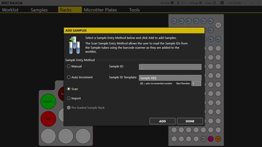
2. Add samples: Click/tap the Add Samples button. The Add Samples window will appear in the
foreground, and the Racks view will appear in the background to allow for monitoring of sample
placement as samples are loaded:
Use the radio buttons to select the Sample Entry Method. Follow the detailed on-screen
instructions for placement of samples using each method.
Important Notes:
Tube Placement: Samples must be placed in the designated blinking positions in the sample rack.
While placing samples, verify that samples are recognized by the software (spaces with loaded
samples display yellow or blue; unoccupied spaces will remain white or grey). Samples are placed
beginning in the back left corner of the rack, and moving from left to right across each row, filling
the rack from back to front.
Note: Eppendorf or other conical-shaped tubes are not recommended for use in the instrument;
only standard-diameter sample tubes are recommended for holding samples.
BOLT-0006.D 10/04/2017 Page 19 of 41Sample IDs: Sample IDs cannot be edited after placement. To edit a sample ID, remove the sample
from the Worklist and add it again with a new ID. Duplicate sample IDs are not permitted; a suffix
will be added to the sample ID if a sample with a duplicate ID is added.
Sample Entry Methods:
a. Manual: Use for non-barcoded samples with custom IDs. Type the sample ID into
designated field and click/tap Add (or press Enter on the netbook keyboard). Place the
sample in the rack as prompted and repeat for all manually-labeled samples.
b. Auto Increment: Use for Auto-numbered samples. Change the Sample ID Template and
Start Number if desired and click/tap Add. Place samples in the sample rack, one by one
as prompted. Samples will automatically be numbered consecutively, beginning with
Sample #1 and continuing with Sample #2, #3, #4 etc. (according to ID Template and
Start Number).
c. Scan: Use for barcoded samples. Click/tap Add. Scan the barcoded sample tube using
an attached handheld scanner. Place the sample in the rack as prompted and repeat for
all barcoded samples.
d. Import: Use to import sample lists from an Excel spreadsheet. Select the desired XLS or
XLSX file as prompted.
Note: This option requires the user to fill in an Excel document template (Inquire with
local distributor for guidelines of proper template format) with all sample IDs and rack
positions locations prior to adding samples to the worklist.
e. Preloaded Sample Rack: Use to add preloaded racks (prepared as described in Worklist
Preparation). Click/tap Add. Select the desired rack from the Preloaded Sample Racks list
and click/tap Add. Scan the rack as prompted (using an attached handheld scanner and
place it inside the instrument (Scanned barcode must match the selected rack in order to
add the rack to the Worklist).
When all samples have been added, click/tap Done to exit the Add Samples window. Display will
return to the Samples tab, where all added samples are listed.
3. Additional Sample Tab Options (optional): Click/tap the sample ID to select sample(s) (selection
is highlighted). Use the CTRL and SHIFT keys to highlight multiple samples.
a. Remove Samples: Click/tap this button to remove highlighted sample(s).
b. Multiply Samples: Click/tap this button to change the replicate of highlighted sample(s).
Use the + and – buttons to adjust the indicated sample multiplication (Sample will be
pipetted multiple times from the same sample tube.)
c. Drag and Drop: Samples will be pipetted in the order listed on the Samples tab. Drag
and drop samples to adjust processing order as desired. (If using a touchscreen, touch
and hold the Sample ID, then tap the Move button which appears and specify new
sample position in the Move Sample window.)
4. Query LIS (optional): If LIS-prompted sample selection is desired and LIS connectivity has been
correctly configured, click/tap the Query LIS button at this time. LIS will select appropriate
samples for the chosen test(s) in the Worklist.
5. Select Samples: If LIS-prompted sample selection is not used, click/tap on the box(es) next to
the samples to select them for test(s). Check marks appear to indicate selection.
BOLT-0006.D 10/04/2017 Page 20 of 41a. Multiple samples can be selected for a test simultaneously by highlighting multiple
samples, then clicking/tapping a box next to a sample to select all highlighted samples
for a test.
b. To select all samples for a test, right click/tap on the desired test name at the top of the
column. All samples in the test column will be selected.
c. If the same test file is run twice in the same Worklist, Use the Smart Fill Tests button to
fill all available sample positions on the first test file and select remaining samples to run
in the second test file automatically.
Following is an example of a Samples tab that has been properly prepared for a Worklist run:
Note: Rack Position is indicated for each sample (rack#1: tube position #).
5.2. Racks Tab
This tab displays the reagent rack and sample racks and is used to load reagents, calibrators, and
controls, and to verify sample placement. Additional information about each position can be seen by
hovering over the desired location. The following steps are taken to complete this tab:
Reagents: Load reagents into the instrument reagent rack using appropriately sized reagent
adapters and following the colors/descriptions indicated on the screen:
1.
a. Use appropriate reagent adapters. Be sure the notched edge of each reagent adapter is
facing forward.
b. If desired, right click/tap on any reagent bottle to set a custom dead volume for that bottle
or to split the bottle into two positions.
c. Reagent locations are automatically assigned, starting in the back of the reagent rack and
proceeding to the front.
BOLT-0006.D 10/04/2017 Page 21 of 412. Calibrators and Controls: Place prepared calibrator and/or control vials into the indicated
locations in the sample rack(s):
a. Calibrator and control locations are automatically assigned to the first available rack
position, beginning with the front right corner and proceeding to the left, then continuing
front to back across the rack in rows (filling rows from right to left).
Note: When a Worklist is started, the Reagent Loading Wizard will also guide the user through the
process of adding reagents and calibrators/controls (if wizard is enabled in the Storm Instrument
Manager Settings).
3. Samples: Verify the placement of all loaded samples.
4. Check: Check for/remove any bubbles from reagent/calibrator/control/sample bottles/tubes.
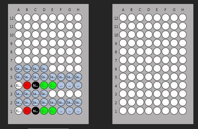
5.3. Microtiter Plates Tab
This tab is used to determine the number of wells/strips/plates required for the run by displaying all
well locations on the microtiter plate (MTP) position and the predilution plate position:
Additional information about each well is displayed on the screen when hovering over the well. The
following steps are taken to complete this tab:
1. Verification: Visually verify that all desired test wells and samples appear on the MTP layout in
the correct plate locations.
2. Wells: Obtain the required number of wells for the test(s) as indicated by the MTP image and
secure them into appropriate plate frame(s).
3. Plate Frames: Place the plate frame(s) with the appropriate wells onto the MTP carrier.
4. Additional Microtiter Plates Tab Options (optional):
a. Exclude Strips: This option, which allows tests to start in plate positions other than the
default A1 position, can only be used if set during Worklist preparation, as described in
previous section.
BOLT-0006.D 10/04/2017 Page 22 of 41b. Predilution Plate Import/Export: These options, which allow predilution plates to be
shared between tests, can only be used in combination with predilution sharing test
files. Contact the local distributor for additional information, if needed.
i. After using a Worklist to create a predilution plate, click/tap the Export button
to save the predilution plate for later use.
ii. To use a previously created and exported predilution plate, click/tap the Import
button and select the desired plate.
iii. Note: If importing a predilution plate, all samples will be removed from the
sample list and replaced by the samples present in the imported plate.
c. Strips Loading Wizard: For monotest/strips assays, the Strips Loading Wizard is enabled.
Click/tap this button to be guided through scanning/placement of each required strip.
5.4. Worklist Tab
This tab displays the Worklist action log and the estimated run time. This tab is used to start, load,
save, monitor, pause, stop, and finish a Worklist. The following steps are taken to complete this tab:
1. Name: Enter the name of the Worklist in this field. If no name is entered, Worklist will be
automatically named with a date and time stamp.
2. Operator: Verify that the correct user is logged in.
3. Verification: Verify that the number of samples loaded and number of tests to run is correct.
4. Wash Bottles: Place appropriate wash bottles in the indicated locations. Note: Wash Bottle 1 is
located in first wash position (closest to the front of the instrument); Wash Bottle 2 is located in
the second wash position (behind Wash Bottle 1).
5. Timing: If desired, click/tap the arrow button at the bottom left of the tab to view estimated
timing of the Worklist actions:
Hovering over the colored bars displays additional information about each action.
6. Start: Press the Start button to start the Worklist.
a. The Special Start button can be used to start the Worklist from a stopped/aborted
position, from a specific step of the selected test(s), or to reread the plate(s) (plates can
only be reread if Worklist has already been run).
7. Check: Check required reagent and calibrator/control volumes as prompted by the Reagent
Loading Wizard (if wizard is enabled). If multiple bottles of a single reagent are required to
accommodate the indicated volume, use the Split Bottle option within the wizard window to
load additional bottle(s). A split bottle can also be removed, if desired, using the Remove Split
Bottle button.
8. Run: Close the lid as prompted and wait for tests to run. Worklist actions can be monitored
throughout the run using the Status Log, the live camera feed, and the timing bar at the bottom
of the screen.
a. It is important to keep cover closed for the entire duration of the Worklist, especially
when using the chemiluminescence option.
b. If necessary, use the Pause button to temporarily pause a Worklist or the Stop button to
completely abort a Worklist (instrument movement will stop and door will unlock).
BOLT-0006.D 10/04/2017 Page 23 of 415.5. Worklist Completion
Standard Worklist Completion:
1. Finish: After the Worklist is completed, click/tap OK to stop the alarm (if end of run sound is
enabled).
2. Remove Kit Components/Samples: Remove microtiter plate(s), reagents, controls, and samples
from inside the instrument.
a. Ensure that all instrument surfaces are clean and dry, and close the cover.
3. Evaluate Results: Instrument user or other designated laboratory employee can
review/display/export/send Worklist and/or sample results on the Evaluation tab as described in
a following section of this manual.
Note: If multiple tests are included in the Worklist, results for each test will become available for
viewing on the Evaluation tab as each one finishes (even if remaining test(s) in the Worklist
is/are not yet completed). User can view results for completed test(s) while Worklist is still in
progress.
4. Perform Maintenance: After each instrument use, verify that the maintenance log is up to date.
If run is the last of the day/shift, click/tap the Power icon and perform daily shutdown
maintenance as prompted (described in the maintenance section of this manual).
Additional Completion Selections (optional):
1. Export Log: Use this button, if desired, to export the Worklist action log to another file location
(it is automatically saved in the Status Log Files folder by default).
2. New: Click/tap New to clear samples and tests from the completed Worklist and allow the setup
of a subsequent new Worklist.
3. Load: Click/tap Load to open and run/rerun a previously saved Worklist. All tests, information,
and samples are loaded when a previously run/saved Worklist file is loaded; it is the user’s
responsibility to ensure that all items are properly placed inside the instrument when running a
loaded Worklist. Test/sample selections cannot be edited within a loaded Worklist.
4. Save: Click/tap Save to save the current Worklist with a new file name or to overwrite a previously
saved Worklist file.
6. Evaluation and Search Tabs
After a Worklist is completed, various options are available for evaluation and review of results in the
Storm Instrument Manager Evaluation and Search tabs. These tabs can be accessed at any time from
within the Storm Instrument Manager in both the Full Functionality Mode (instrument computer) as well
as in the Evaluation Only mode (on instrument computer or another/server computer). If desired, the
person reviewing all Worklist results can be different from the person operating the instrument(s) and
results from all instruments connected to the same Storm Server can be reviewed on one central
computer.
6.1. Evaluation Tab
This tab is used to review Worklist results. Users can view, export, and print Worklist reports, mark
a Worklist as reviewed, review Worklist errors, change test properties and drop replicas, and send
results to the LIS on this tab.
BOLT-0006.D 10/04/2017 Page 24 of 41You can also read