Study on Flexible Polishing Force and Polishing Temperature of Flap Disc
←
→
Page content transcription
If your browser does not render page correctly, please read the page content below
Study on Flexible Polishing Force and Polishing Temperature of Flap Disc De Liu ( ldhnbc@163.com ) Wenzhou University Xiaoming Pan Wenzhou University Zhiyang Gu Wenzhou Polytechnic Hui Qiu Wenzhou University Research Article Keywords: Flexible polishing, Abrasive cutting, Polishing force, Polishing heat, Speci c polishing energy Posted Date: July 12th, 2021 DOI: https://doi.org/10.21203/rs.3.rs-626617/v1 License: This work is licensed under a Creative Commons Attribution 4.0 International License. Read Full License
Study on flexible polishing force and polishing temperature of flap disc
 De Liu1, Xiaoming Pan* 1, Zhiyang Gu2 and Hui Qiu1
1
 College of Mechanical and Electrical Engineering, Wenzhou University, Wenzhou 325035, China
2
 Department of electrical and Electronic Engineering, Wenzhou Polytechnic, Wenzhou 325035, China

----------------------------------------------------------------------------------------------------------------------------------------------------------------------------------------------------------------------------------------------------------------------------------------------

Abstract
 Polishing determines the final surface quality of the aero engine, which have great influence on its working performance and working
life. By analyzing the structure and working principle of the flexible self-adaptive polishing platform of the blisk, the abrasive cutting model
of the flap disc is established. The theoretical calculation of the effect of elastic deformation during the polishing process on the contact
length of flap disc and blisk. The model of polishing force, polishing heat and temperature field during the polishing process of the flap
disc are established and analyzed. Single factor method is used to analyze the influence of process parameters on polishing force, polishing
temperature, roughness and specific polishing energy. Finally, the polishing test shows that the optimized process parameters improve the
polished surface quality and meet the requirements of the blade polishing process.

Keywords: Flexible polishing; Abrasive cutting; Polishing force; Polishing heat; Specific polishing energy
----------------------------------------------------------------------------------------------------------------------------------------------------------------------------------------------------------------------------------------------------------------------------------------------

 Wang studied the spiral brushing force through theory and finite
1. Introduction
 element method [4]. Liu studied the surface roughness and re-
 The Integral blisk of aero engine has the characteristics of sidual stress of the polished aero engine blisk and blade surfaces,
complex blade surface, thin blade body, long blade extension, optimized the polishing process, and improved the surface in-
poor rigidity and uneven processing allowance, etc. Therefore, tegrity [5-7]. Zhang studied the polishing of blisk with the abra-
the polishing process of the blisk is demanding. There are still sive belt, optimized the process parameters, and the surface
many deficiencies in the polishing equipment and process tech- roughness was reduced [8]. Liu optimized the tool path and the
nology of the complex curved surface. Manual polishing is still shape of flap disc to avoid the occurrence of knife marks [9].
the main processing method. The processing efficiency is low, Wang used the abrasive cloth wheel to polish the free-form sur-
the working environment is hard, the workpiece processing ac- face. By planning the direction of the knife axis, the polishing
curacy and surface quality are greatly affected by the worker's surface roughness was reduced [10]. Huai established the pre-
experience. The processing accuracy is low and the processing diction model for the polishing surface roughness of abrasive
surface consistency is difficult to guarantee. Therefore, the pol- cloth wheel, and the process parameters were optimized to re-
ishing process has attracted attention and a series of studies duce the polishing surface roughness [11,12]. Ma polished the
have been done. additive titanium alloy by means of laser polishing, and the la-
 Wu studied the polishing of M300 Mold steel with elastic ser polished surface and cross-section subsurface were ana-
abrasive, and the polishing parameters was optimized by lyzed by white light interference, confocal microscope, focused
Taguchi method so that educe the surface roughness [1]. Xian ion beam, scanning electron microscope, energy dispersive
studied the vibration characteristics of the polishing blade with spectrometer and X-ray diffraction [13]. Xiao illustrated the
the abrasive cloth wheel, and the blade damage caused by vi- methodology of CABP and established an equation for micro-
bration was reduced [2]. In order to control the vibration of pol- displacement in constant-load adaptive control to improve the
ishing process, Lin proposed a method of predicting the value accuracy and the consistency of the polishing blade surface
of polishing vibration signal. The empirical model of process quality [14]. Tian studied the automatic polishing of surfaces by
parameters for polishing vibration was established [3]. Aiming robots, analyzed the relationship between polishing pressure
at developing a mobile robot system to perform rust removal, and removal efficiency, and the quality of polished surfaces
 were improved by controlling the pressure [15]. Janus used two
 polishing methods to process different nanomaterials, com-
 pared the effects of surface roughness and micro-morphology
Corresponding author: Xiaoming Pan before and after polishing [16]. Antonson and gönülol com-
 E-mail address: 00132004@wzu.edu.cn
 pared the effects of different polishing systems on composite
 materials, compared the effects of surface roughness and gloss,
 1
 College of Mechanical and Electrical Engineering, Wenzhou University, Wen- etc. The best polishing method was determined [17,18].
 zhou 325035, China
 Evgueni reviewed the progress of laser polishing technology in

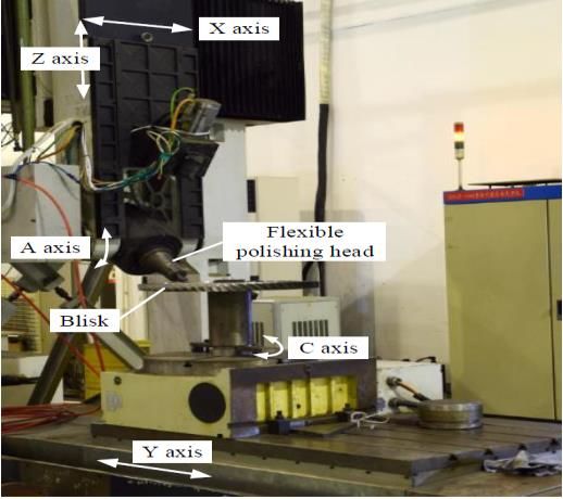
theoretical and experimental research, and emphasized the pro- controlled by the servo motor that controls the movement of the
cessing performance defined by the surface roughness before A-axis to complete the swing movement, and the range of
and after polishing [19]. Berger investigated the influence of swing angle is 0 ~ 90°. The blisk is fixed on the worktable by
filler size and finishing systems on the surface roughness [20]. fixture, and the C-axis servo motor controls its rotation, and the
Zhang established the prediction model of roughness for abra- range of rotation angle is 0 ~ 360°.
sive belt polishing, optimized the process parameters and im- In order to achieve multi-axis linkage and control the move-
proved the quality of the polished blisk [21]. ment trajectory accurately, the integral blisk polishing experi-
 Northwestern Polytechnical University developed a five-axis ment platform adopts siemens system, simodrive 611D power
CNC polishing machine independently, which has both the tra- module, simatic S7-200 logic controller (PLC) to form a fully
jectory precision of the CNC machine tool and the control unit digital control system. The computer control is used as the nu-
of the polishing force. The flap disc with simple structure and merical control system, which has the advantages of modulari-
good elasticity is used as an abrasive tool. The flap disc can be zation and digital control. It is convenient to complete infor-
deepened into the blisk of the aero engine for adaptive polishing, mation interaction with other equipment, so as to efficiently
which can effectively reduce the occurrence of over-polishing control the equipment to complete the processing of the blisk.
and under-polishing[22]. The surface of the blisk is a free-form surface. It is difficult
 to accurately plan the polishing trajectory, which leads to devi-
2 Working principle of polishing machine ations between the theoretical polishing path and the actual pol-
 ishing path. For this phenomenon, the machine tool spindle can
 A five-axis CNC polishing machine with a gantry structure
 monitor the machining process in real time, and the spindle
is used as the polishing equipment. The experimental platform
 mechanism can perform floating adjustment of the polishing
is a polishing system that integrates polishing force control and
 process, so that the micro-displacement between the spindle
micro-displacement adjustment. The integral blisk polishing
 mechanism and the tool can be automatically adjusted, and the
machine is shown in Fig. 1. The machine tool contains five co-
 elastic contact between the tool and the workpiece can be en-
ordinates. The grinding spindle can complete linear motion in
 sured by the floating adjustment of the polishing force. Besides,
the vertical plane composed of X-axis and Z-axis, swing motion
 the spindle mechanism can set the difference interval between
around A-axis within a certain range of angle. The rotating
 the actual polishing force and the theoretical polishing force ac-
worktable carries the blisk, rotates around the coordinate C-axis
 cording to the processing requirements to ensure the dynamic
on the same horizontal plane, and moves linearly along the Y-
 and stable control of the polishing force and reduce the pro-
axis. Two rotary coordinate axes A and C, three linear coordi-
 cessing error caused by the unreasonable polishing path.
nate axes X, Y, Z cooperate to complete the linear movement
 The main components of elastic grinding spindle to realize
and rotary movement of the workpiece and the grinding spindle,
 flexible polishing include control cylinder and displacement
so that control the processing track of the workpiece. The main
 sensor to realize displacement adjustment, spindle outer sleeve
components of the polishing experiment platform are the col-
 and inner sleeve for protecting and supporting components,
umn that supports the workpiece, the box for loading the spin-
 swing support shaft, cylinder support cover, spring chuck for
dle, the spindle for polishing the workpiece, the rotatable work
 positioning, electric spindle that provides power for tool rota-
platform, the base, the machine tool guard, the clamping tool,
 tion. The structure of the flexible grinding spindle is shown in
the shaft guard, and the servo motor that controls the movement,
 Fig. 2. The main shaft is installed with a sleeve embedded struc-
etc. The electro-spindle and its flexible control mechanism are
 ture, and the control cylinder runs through the inner sleeve of
located in the spindle box. The electro-spindle mechanism is
 the main shaft and is located between the inner sleeve of the
 X-axis
 Servo
 Z-axis
 electrode

 Headstock
 Z-axis

 Spindle
 mechanism

 Flexible polishing
 A-axis spindle Upright

 A-axis
 Rotating
 Blisk
 table
 C-axis C-axis
 safety
 mask

 Machine
 Y-axis
 base

 (a) Polishing machine (b) Three-dimensional model
 Fig. 1 The integral blisk polishing machine
main shaft and the central main shaft. The cylinder and the cyl- shaft drives the flap disc to rotate at high speed, and the abrasive
inder support cover connect the spindle inner sleeve and the cloth sheet is fully stretched under the action of centrifugal
spindle outer sleeve. Three groups of cylinders are evenly dis- force, so that the flap disc and the workpiece are fully attached
tributed along the radial direction of the polishing spindle at a to achieve shape-followed polishing. This polishing method has
certain angle. There is a cylinder at the top of the spindle along a larger contact area and a more uniform polishing force, which
the axial direction. The four groups of cylinders control the can effectively reduce the occurrence of over-polishing or un-
grinding spindle to achieve radial micro-movement. The cylin- der-polishing, improve the surface quality of polished free-
ders cooperate with each other to complete the adjustment of form surfaces.
the spindle's pose. The displacement sensor and the cylinder are (2) The flap disc and the workpiece are in elastic contact, and
arranged in pairs, and they are installed on both sides of the system has good stability during polishing. The polishing force
main shaft in parallel to detect and adjust the displacement of of the flap disc is relatively small, so that the deformation of the
the main shaft. The swing support shaft of the main shaft is lo- workpiece is relatively small, and the workpiece with poor ri-
cated in the main shaft box to realize the swing of the main shaft gidity can also have a good polishing effect. At the same time,
along the A-axis. the flap disc rotates at a high speed, the removed abrasive par-
 Control cylinder ticles are separated from the abrasive tool under the action of
 centrifugal force, which is helpful to reduce the polishing tem-
 Motion detector perature and prevents burns on the workpiece.
 (3) The flap disc has a simple structure, does not require a
 Spindle jacket complicated external support structure. In addition, due to the
 Spindle inner small size of the flap disc, it can go deep into the flow passage
 sleeve of the blisk, so that achieve a good polishing effect on the free-
 Swing support form surface.
 shaft
 Cylinder support
 2.2 Abrasive cutting process model
 shaft
 The flap disc is a kind of micro-edged cutting tool. In the
 Electric spindle
 process of material removal, the tool rotates at high speed, so
 Collet that a large number of fine abrasive particles are drawn across
 the surface of the workpiece to complete the removal of the ma-
 Fig. 2 Structure distribution of flexible grinding spindle terial. The removal effect of a large number of abrasive parti-
 cles are superimposed to complete the polishing process. In or-
 The grinding spindle is a key processing unit for the machine
 der to understand the polishing mechanism of the flap disc, it is
tool to realize flexible polishing. It can realize elastic contact
 necessary to analyze the cutting process of a single abrasive
between the tool and the workpiece, reducing the occurrence of
 particle.
over-polishing or under-polishing. The displacement sensor on
 The material removal process model of a single abrasive par-
the grinding spindle monitors the changes of spindle pose in
 ticle of the flap disc is shown in Fig. 3. According to the differ-
time, collects relevant data signals and inputs them into the in-
 ent material removal effect of abrasive particles, it can be di-
dustrial control system. The data signal is analyzed through the
 vided into sliding, ploughing and cutting.
control algorithm, and the output signal command is used to
 During the polishing process, the abrasive particles and the
control the expansion and contraction of the cylinder to realize
 surface of the workpiece are squeezed to generate heat and de-
the micro-displacement adjustment of the spindle. Through the
 formation, which is the main cause of thermal stress and defor-
adjustment of the spindle's pose, the stable control of the spin-
 mation stress. When the contact force between the abrasive par-
dle polishing force is ensured. The micro-displacement adjust-
 ticles and the material is small, and the deformation is recover-
ment can effectively compensate the deviation between the ac-
 able elastic deformation, it is in the sliding stage. When the
tual polishing path and the theoretical polishing path caused by
 abrasive particles squeeze the material and the material pro-
tool wear and inconsistent machining allowance.
 duces irreversible plastic deformation without material falling
 off, it is in the plough stage. If the abrasive particles cut the
2 Flexible polishing mechanism of flap disc
 workpiece, the removed material fragments are separated from
2.1 Technical characteristics of flap disc polishing the workpiece and flow out along the rake face of the abrasive
 The experiment chooses the flap disc as the polishing tool. In particle micro-edge, it is in the cutting stage. According to the
the process of polishing the blisk, the main characteristics of the cutting performance of the material and the sharpness of the
flap disc are as follows. abrasive micro-edge, it will affect the processing stage of the
 (1) The flap disc is a flexible polishing method. Firstly, the material removal model.
flap disc abrasive binder has a certain elasticity. In addition, the The rotation speed of the flap disc also affects the formation
flap disc selects a cloth base with good flexibility as the abra- of friction, ploughing and cutting of abrasive particles on the
sive carrier. During the polishing process, the rotating main cutting surface. The higher the rotating speed, the smaller the

Base Sliding Flap disc Binder material Ploughing z c Cutting a o (y) x Abrasive grain n Blade Fz Fx Fig. 3 Polishing abrasive grain cutting model of flap disc elastic-plastic zone. The actual cutting amount of a single abra- and the workpiece can be solved by the elastic contact model. sive partical is different, and the elastoplastic deformation zone The normal polishing force causes the displacement of the flap is also different. Because the binder of the abrasive particles has disc and the workpiece e’, which can be analyzed according to a certain elasticity, the abrasive particles will retreat under the the contact model that does not consider the cutting depth, Fig. action of cutting force, which makes the actual contact curve of 5(a). The contact displacement between abrasive particles and the abrasive particles and the workpiece different from the the- workpiece e”, which can be analyzed according to the contact oretical contact curve. In addition, in the process of material re- model that consider the cutting depth, as in Fig. 5(b). Where ds moval, the force between the abrasive particles and the work- is the diameter of the flap disc. piece causes deformation. When the abrasive particles are sep- Flap disc arated from the material, the deformation of the material is re- stored, so that the theoretical cutting path does not match the ds b Abrasive rg grain actual profile, which affects the accuracy and surface roughness. Fn e e The elastic retreat and elastoplastic contact area of abrasive par- dw ticles are shown in Fig. 4. Blade hp Surface generation curve (a) Contact displacement e (b) Contact displacement e Material removal part Real interference Fig. 5 The grinding contact model curve Surface after grinding According to the contact model that does not consider the cutting depth, the contact displacement between the flap disc and the workpiece is calculated as shown in Eq. (2). Where Fn is normal cutting force, b is the width of flap disc, vw and vs Theoretical Plasticity are the poisson's ratio of the workpiece and the flap disc. Ew interference curve Elasticity and Es are the elastic modulus of workpiece and the flap disc. Cutting Plastic deformation 2 1 1 − 2 1 − 2 1 − 2 4 1 − 2 4 ′ = [ ( + )+ ln + ln ] (2) 3 Wear debris The abrasive grain cutting edge is in contact with the work- Elastic deformation piece and produces a contact displacement. The abrasive grain Fig. 4 The elastic retreat and elastoplastic contact area of abra- is regarded as an elastic sphere with a radius of rg. By consider- sive particles ing the contact model of cutting depth and the abrasive grain cutting edge, the force generated by the abrasive grain displace- 2.3 The influence of elastic deformation on the contact length ment e” is solved , as shown in Eq. (3). In the process of polishing the blade, the flap disc has good 1/3 9 1 − 2 1 − 2 flexibility, which can be regarded as an elastic body. Under the " = [ ( + ) ] 16 action of the normal polishing force, it will cause the flap disc and the workpiece to produce contact displacement e’, the The contact arc length between the flap disc and the work- abrasive grains and the workpiece to produce contact displace- piece is ls, as shown in Eq. (4). where "+" means polishing the ment e”, the sum of the two e is shown in Eq. (1). outer arc at the back of the blade, and "‒" means polishing the inner arc at the basin of the blade, hp is the cutting depth = ′ + " of abrasive grains, dw and ds are the contact diameter(1) of work- The contact displacement of the flap disc, abrasive particles piece and flap disc.
= + = ∑ + ̅ ̅
= √ (√ℎ + + √ ) { (4)
±
= + = ∑ + ̅ ̅
Material cutting area per unit area of abrasive particles is
3 Study on polishing force and polishing temperature shown in Eq. (13). The average polishing pressure of the abra-
sive particles is shown in Eq. (14), and
3.1 Analytical model of polishing force
∑ = ℎ
Polishing force is an important characterizing parameter of
the polishing process, which has an important influence on the ̅ =
̅
surface quality and machining accuracy. In order to establish The total number of abrasive grains per unit polishing area of
the analytical model of polishing force, it is necessary to deter- the flap disc is N, as in Eq. (15).
mine the contact dynamic effective grinding edge number of 1+ 1−
= ∫ = ( ) ( ) (ℎ ) 2 ( ) 2 (15)
the contact surface between the flap disc and workpiece in unit 0 1+
area and the average cutting area within the contact arc length.
The dynamic effective number of grinding edges on the in- Substituting Eq. (13) and Eq. (15) into Eq. (12), the radial
terface between flap disc and workpiece Nd is shown in Eq. (5), and tangential polishing forces per unit area can be obtained, as
the contact dynamic effective grinding edge number of the con- in Eq. (16).
̅ ̅ 1+ 1−
tact surface between the flap disc and workpiece in unit length = ( ℎ ) + ( ) ( ) (ℎ 2 2 )
1+
Nd(l) is shown in Eq. (6), where An is the proportional coeffi- (16)
̅ ̅ 1+ 1−
cient related to the number of static grinding edges, Ce is the = ( ℎ )+ ( ) ( ) (ℎ 2 2 )
{ 4 1+
coefficient related to abrasive density, α and β are constant
terms.
3.2 Analytical model of polishing temperature
ℎ 2 The blisk and blades of the aero-engine
= ( ) ( ) ( ) (5) are made of titanium
alloy materials with low thermal conductivity. The polishing
ℎ 2 heat increases the
( ) = ( ) = ( ) ( ) ( ) ( ) (6)temperature in the polishing area of the work-
piece, which has a great influence on the surface quality of the
The average value of the maximum material removal cross- workpiece and the cutting performance of abrasive particles.
sectional area ̅ is shown in Eq. (7). The average material (1) During the polishing process, the contact area ABCD of
removal area ̅( ) at contact arc length l is shown in Eq. (8). the flap disc and the workpiece moves relative to each other to
1−
2 1− ℎ 2 generate polishing heat.
̅
= ( ) ( ) ( )
− (7) Assuming that this area is a uniform
and constant surface heat source, the heat per unit area per unit
1−
̅ ( ) =
̅ 1− 2 1− ℎ 2 1− time is q.
( ) = ( )− ( ) ( ) ( ) (8)
(2) During the polishing process of the flap disc, the heat
The radial polishing force between the flap disc and the transferred to the blade is %, and the blade is regarded as a
workpiece is shown in Eq. (9), where K and n are proportional semi-infinite heat conductor, and the heat generated by the heat
coefficients related to abrasive particles. source is qm=q.%.
′ = [ ̅( )] ( ) (9)
(3) Generally, the radius of the blade is much larger than the
Integrate the entire arc length to get the radial polishing force
radius of the flap disc, and the contact area ABCD of the flap
Fn, as is in Eq. (10).
disc and the blade is regarded as a plane.
( ) = ∫ [ ̅( )] ( ) (4) The length of surface (10) heat source ( ) =
0
2
Substituting Eq. (6) and Eq. (8) into Eq. (10), Eq. (11) can be √ 2 − ( − ) = √2 − 2 , where rs is the working
1
obtained. Where = [(1 + ) + (1 − )] , = (1 −
2 radius of flap disc, ap is the amount of compression.
)。 (5) Ignore the influence of material removal depth and tool
2 −1
( ) = ( ) ( ) (ℎ ) ( )1− (11)
wear on heat generation.
According to the analysis of the above polishing process, the
Polishing force is mainly composed of cutting force and fric-
heat transfer model of the flap disc polishing blade can be re-
tion force. Based on the mathematical model of grinding and
gard as an infinite width and finite length moving surface heat
polishing force, the polishing force model is expressed as two
source problem, which can be simplified to a two-dimensional
parts, as in Eq. 12. Where Ft is tangential force, and
heat conduction problem, as in Fig. 6.
are the radial force and tangential force caused by cutting de-
formation, and are the radial force and tangential
force caused by friction, ̅ is the actual contact area between
the abrasive particles and the workpiece, ̅ is the average con-
tact pressure between abrasive particles and workpiece, =
.
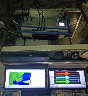
4 tan z −( + )2 + 2 = ∫ 4 rs-ap 4 0 rs Flap x disc vw According to the analysis of the two-dimensional heat con- duction problem, the surface heat source ABCD can be re- Blade garded as a synthesis of countless linear heat sources, and y these linear heat sources move along the X direction at a speed of vw. Take the surface heat source dXi for analysis, as in Fig. 6(b). The surface heat source intensity is qmdXi (a)Heat transfer model (cal/cm.s), the temperature distribution equation is (x,t), A is the cross-sectional area of heat conduction, Q is the Z Z amount of heat change, and a are constants. C dxi Vw According to the Eq. (21) and the principle of the adiabatic surface caused by the mirror image heat source, the temper- D X E X O E O dxi ature rise of point M in the x z plane of the workpiece affected B z A M M(x,z) xi xi l l by the dXI motion heat source is shown in Eq. (22). Where 0 = ( √ 2 + 2 /4 ) − , γ is Euler's constant. x ( − ) Y = ∫ 0 [ √( − )2 + 2 ] (2 (b) Simplified heat transfer model 0 2 2 Fig. 6 Heat transfer model of blade polishing Combine Fourier's law of heat conduction with Talau se- ries to analyze the change in temperature dθ of the micro- 4 Polishing test and analysis element body over time dt, as is shown in Eq. (17). 4.1 Experimental conditions ∆ ( , ) 2 The five-axis CNC machine is used as the processing d = = 2 t equipment, the TC-17 titanium(17) alloy blade is the test piece, and the material composition is shown in Table 1. The flap A point heat source in an infinite conductor emits instan- disc is the abrasive tool for polishing test. The dynamic pie- taneous heat Q at time t, and the temperature θ of an arbitrary zoelectric force gauge is fixed on the rotary table through the point M(x, 0, z) in the vertical plane of the heat conductor is fixture to measure the polishing force (as in Fig. 7(a)), the shown in Eq. (18). 2 = −4 Z (18) (4 ) C At the moment di, the heat generated by polishing qsdi O causes an rise in temperature at point M, which is regarded A X as an instantaneous line heat source for calculation. Y d ( − )2 + 2 Flap disc d = − 4 Blade (19) (4 ) At the moment of di, the heating of the sports heat source is regarded as instantaneous heating. The starting time of the Dynamic piezoelectric Fixture action is i, and the time from this moment to the observation force gauge time t is . The distance between the observation point M and (a) Experimental platform the heat source in the x direction is x - vi. In order to make the solution of the motion temperature field more convenient, a motion coordinate system is established, = t - i. x - vi = x - v t + v =X + v. And Eq. (20) can be obtained. A Collection of temperature Collection of polishing force d ( + )2 + 2 d = − 4 (20) (4 ) Z During the whole process from I = 0 to I = t, the heat Charge amplifier source of the moving line causes the temperature rise of point Bracket M as in Eq. (21). (b) Infrared thermograph (c) Signal acquisition system Fig. 7 Measurement of polishing force and temperature
infrared thermal imager is used to measure the polishing tem- heat. In addition, as the polishing speed increases, the num-
perature (as in Fig. 7(b)), and the signal amplifier is used to ber of abrasive particles scratching on the blade surface per
collect polishing force and polishing temperature signals (as unit time will increase, which will also lead to an increase in
in Fig. 7(c)). polishing temperature.
Table 1 Chemical composition of TC17 titanium alloy

 Ingredients Contents (%) Ingredients Contents (%)
 Al 4.5–5.5 Mo 3.5–4.5
 Sn 1.6–2.4 Cr 3.5–4.5
 Zr 1.6–2.4 Ti Bal.

4.2 Experimental analysis
 Polishing force, polishing temperature and specific polish-
ing energy are closely related to material machinability, ma-
terial removal efficiency and surface quality. The influence
of parameters on polishing force and polishing temperature
is the basis for improving processing efficiency and surface
quality.
 The single factor method is used to study the influence of Fig.9 The influence of Vs on Ra and es
polishing speed Vs, compression quantity ap, feed speed f, and As shown in Fig. 9, the roughness decreases at first and
size p on polishing force F, polishing temperature T, specific then increases with the increasing of polishing speed. When
polishing energy es and surface roughness Ra. the polishing speed is small, the abrasive cloth piece on the
 flap disc is not fully expanded, and the flexibility of the flap
 n
 disc is poor, resulting in a larger roughness. As the polishing
 t
 speed increases, the flap disc obtains good flexibility and the
 polished surface roughness is reduced. As the polishing
 speed continues to increase, the polishing force of the flap
 disc is too large, which leads to the excessive material re-
 moval depth and the roughness becomes larger. The specific
 polishing energy increases with the increase of polishing
 speed. The specific polishing energy increases with the in-
 crease of polishing speed. The reason is that with the increase
 of polishing speed, the contact time between the blade and
 the abrasive cloth piece becomes shorter. The energy con-
 sumption of material removal per unit volume increases with
 Fig.8 The influence of Vs on F and T the cutting form of abrasive grains change to ploughing form.

 As shown in Fig. 8, as the polishing speed increases, both
the radial polishing force and the tangential polishing force
 n

show an increasing trend, and the radial polishing force
 t

changes more sensitively. The high-speed rotating flap disc
obtains good flexibility under the action of centrifugal force
and produces radial polishing force on the blade. As the pol-
ishing speed increases, the spindle speed has a greater rota-
tion speed, and the flap disc obtains greater centrifugal force,
resulting in a greater radial polishing force. The force of the
flap disc on the blade is small, and the cutting depth of the
abrasive particles is small. Therefore, the tangential re-
sistance encountered during the rotation of the flap disc is
small and the sensitivity of the tangential force to polishing
speed is not obvious. As the polishing speed increases, the Fig.10 The influence of ap on F and T
polishing temperature rises accordingly. The higher the sur- As shown in Fig. 10, as the compression quantity increases,
face polishing speed, the higher the limit stress of the mate- both the axial polishing force and the radial polishing force
rial, and the higher the yield limit of the material. It makes show an upward trend. Analyzing the reasons for this change,
material removal require more energy and generates more the increase of compression quantity leads to an increase in
the elastic deformation of the flap disc and the number of change of the feed speed has no effect on the elastic de-
abrasive particles involved in polishing increases, which formation of the flap disc and the material removal depth
causes an increase in the radial polishing force. The increase of the abrasive particles. Therefore, there is no significant
of compression quantity leads to the increase of abrasive cut- change in the radial polishing force and the tangential pol-
ting depth, and more abrasive particles is removed into the ishing force. The polishing temperature decreases as the
cutting stage, resulting in a greater tangential polishing force. increase of feed speed. The reason is that as the feed speed
The increase of the tangential polishing force indicates in- increases, the heat dissipation conditions are improved.
creases of the friction between the flap disc and the blade, However, the friction between the blade and the flap disc
which causes the increase of polishing heat. Therefore, as the does not change significantly, and the heat generated per
increases of compression quantity, the polishing temperature unit time does not change significantly, so the polishing
is improved. temperature is reduced.

 Fig.11 The influence of ap on Ra and es

 As is in Fig.11, the roughness first decreases and then
increases with the increase of compression quantity. The Fig. 13 The influence of f on Ra and es
main reason is that when the compression quantity is
small, the abrasive grains are mainly in the scratching As is in Fig. 13, the roughness first decreases and then
stage, the amount of material removal is insufficient, the increases with the increase of feed speed. The reason may
milling residual height cannot be completely removed, be that when the feed speed is small, abrasive particles cut
and the roughness is relatively large. As the compression more times on the blade, and the material removal depth
quantity increases, the specific polishing energy is im- is greater, and excessive cutting depth is not conducive to
proved. The main reason may be the increase of the com- forming a good polished surface quality. As the feed
pression quantity, which accelerates the wear of abrasive speed increases, the depth of material removal tends to be
grains, causes passivation of abrasive grains, and in- reasonable and the roughness is reduced. When the feed
creases the energy consumption of removing materials per speed is too big, the cutting times of abrasive grains on
unit volume. the blade is too small, and it is insufficient to remove the
 milling residual height, resulting in a greater roughness.
 n
 As the feed speed increases, the specific polishing energy
 t
 is reduced. The main reason may be that as the increase of
 the feed speed abrasive particles are effectively contact
 with the milling residual height layer on the blade surface,
 the material removal efficiency of abrasive particles is im-
 proved, the energy of removing materials per unit volume
 is reduced, and the specific polishing energy is reduced.

 Fig.12 The influence of f on F and T

 As is in Fig. 12, the increase of feed speed has no
significant effect on polishing force. The reason is that the
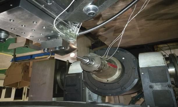
The influence of size on roughness and specific polish-
 ing energy is shown in Fig. 15, the roughness first de-
 creases and then increases with the increase of size. When
 the size is small, the volume of abrasive particles is larger,
 the material removal ability is stronger, the texture pro-
 duced by polishing is more obvious, and the roughness is
 larger. As the particle size increases, the volume of abra-
 sive particles decreases, the width and depth of material
 removal tends to be reasonable, the roughness decreases.
 As the size continues to increase, the amount of material
 removed by abrasive particles is not enough to remove the
 milling residual height of the blade, resulting in an in-
 crease in roughness. As the size increases, the specific
 polishing energy is improved. The main reason may be
 that as the increase of the size, the volume of abrasive par-
 Fig. 14 The influence of p on F and T ticles is reduced, the material removal ability is reduced,
 and more energy is consumed to remove a unit volume of
 The influence of size on polishing force and polishing
 material.
temperature is shown in Fig. 14, with the increase of size,
the radial polishing force does not change significantly,
 5 Polishing test verification
and the tangential polishing force increases slightly. The
reason may be that as the size increases, the number of
 According to the influence of process parameters on
abrasive particles per unit area on the surface of the flap
 roughness, when the polishing speed is 6.2 m/s, the compres-
disc decreases, while the number of abrasive particles in-
 sion quantity is 0.8 mm, the feed speed is 200 mm/min, and
creases. Therefore, the change of size has little effect on
 the size is 600 #, the polished surface roughness is small. The
the quality of the flap disc. When the spindle speed and
 optimized parameters are used for polishing experiments.
compression quantity are constant, the radial polishing
 The comparison of polishing test results are shown in Table
force does not change significantly. With the increase of
 2. It can be seen from Table 2 that after parameter optimiza-
the size, the material removal ability of the abrasive par-
 tion, the polishing force is smaller, the polishing temperature
ticles is weakened, and more abrasive particles are trans-
 is lower, and the roughness of the polished surface is smaller.
formed into the scratch stage. The friction coefficient be-
tween the flap disc and the blade is reduced, so the tan-
 Table 2 Comparison of polishing test results
gential polishing force decreases. The polishing tempera-
ture decreases as the size increases, the reason may be that
the radial friction of the flap disc to the blade does not Category Fn Ft T es Ra
change much and the friction coefficient is reduced. Traditional 5.7 3.5 65 0.17 0.429
Therefore, the heat generated by the polishing is reduced,
and the polishing temperature is reduced. Optimized 4.2 2.5 45 0.24 0.372

 The comparison of traditional and optimized polished sur-
 face effect is shown in Fig. 16. The residual height of the
 milled blade surface is relatively large. The roughness of
 milled blade is 1.465 μm, and there are microscopic cracks
 on the surface. The width and thickness of traditional polish-
 ing debris are relatively large, the surface roughness of pol-
 ished blade is 0.429 μm, and the texture is relatively obvious.
 After parameter optimization, the wear debris is relatively
 thin and small, the surface roughness is 0.372 μm, and the
 surface consistency is better.
 The above analysis shows that after parameter optimiza-
 tion, a smaller polishing force is beneficial to reduce the size
 of wear debris and eliminate the surface texture of the blade.
 Besides, after optimization, the polishing temperature is
 lower, which is beneficial to reduce the thermal deformation
 Fig. 15 The influence of p on Ra and es of the workpiece surface, and the processing accuracy is im-
 proved. Therefore, after optimization, the polished surface
has a smaller roughness and a higher consistency. Provincial Natural Science Foundation of China under Grant
 No. LY20E050027 and the Zhejiang Provincial Natural Sci-
 ence Foundation of China under Grant No. LY19F030006.
 Optimized

 Conflicts of interest/Competing interests I would like
 to declare on behalf of my coauthors that the work de-
 0.372 μm Wear debris
 scribes original research that has not been published pre-
 viously and is not under consideration for publication
 0.429 μm elsewhere, in whole or in part.
 Traditional

 1.465 μm Availability of data and material The material selection
 and data obtained in this manuscript have been tested or
 Milling surface calculated theoretically, which are true and reliable.
 Wear debris

 Microcrack Code availability Not applicable.

Fig. 16 The comparison of traditional and optimized polished
 Authors' contributions The abrasive cutting model of
surface the flap disc is established. The theoretical calculation of
 the effect of elastic deformation during the polishing pro-
6. Conclusions cess on the contact length. The model of polishing force,
 The principle of flexible polishing of the elastic spindle is polishing heat and temperature field during the polishing
analyzed, the cutting process model of the flap disc and the process of the flap disc are established and analyzed. Sin-
model of the influence of the flap disc elastic deformation on gle factor method is used to analyze the influence of pro-
the contact arc length are established. cess parameters on polishing force, polishing temperature,
 The analytical model for the polishing force and polishing roughness and specific polishing energy.
temperature of the flap disc is established. The experiment
shows that as the polishing speed increases, the polishing
 Ethics approval The submission of this manuscript in-
force, polishing temperature and specific polishing energy volves no conflicts of interest, and the manuscript has
increase, and the roughness first decreases and then increases. been approved for publication by all authors.
As compression quantity increases, the polishing force, pol-
ishing temperature and the specific polishing energy increase,
and the roughness first decreases and then increases. As the Consent to participate All the authors listed have ap-
feed speed increases, the polishing force does not change sig- proved the manuscript as enclosed.
nificantly, the polishing temperature and specific polishing
energy decrease, and the roughness first decreases and then
 Consent for publication We would like to submit the
increases. With the increase of size, the radial polishing force
 enclosed manuscript, entitled “Study on flexible polish-
does not change much, the tangential polishing force and
 ing force and polishing temperature of flap disc”, which
temperature decrease, the specific polishing energy increases,
 we wish to be considered for publication in The Interna-
and the roughness first decreases and then increases.
 tional Journal of Advanced Manufacturing Technology.
 The traditional and the optimization polishing experiments
are compared, after optimization, the polishing force, polish-
ing temperature and polishing surface roughness are im-
 References
proved, but the specific polishing energy is increased. Be-
sides, after the optimization, the size of the wear debris is
smaller and the consistency is higher. 1. Wu XJ, Tong X, Sun H (2018) Parameter Optimiza-
 tion of Polishing M300 Mold Steel with an Elastic
 Abrasive. Math Pro Engi, 2018:1-9
 2. Xian, C, Shi, Y, Lin X and Liu D (2020) Study on
Declarations vibration characteristics polishing rod for polishing
 aeroengine blade with abrasive cloth wheel. Math
 Prob Engin 2020(90): 1-14
 Funding This research was supported by the Zhejiang
3. Lin X, Yang R, Xin X (2020) Modeling and Parame- son of different finishing/polishing systems on sur-
 ter Optimization of Flexible NC Polishing Vibration face roughness and gloss of resin composites. J Den,
 of Abrasive Cloth Wheel Based on Sensitivity Anal- 39: e9-e17
 ysis. Math Prob Engi 2020(6):1-12 18. Gönülol N, Yılmaz F (2012) The effects of finishing
4. Wang C, Guo H, Zhao Y, Sun Q, Zhao L (2018) Sta- and polishing techniques on surface roughness and
 tistical analysis of industrial grinding brush force color stability of nanocomposites. J dent, 40: e64-e70
 characteristics based on finite element approach. 19. Bordatchev EV, Hafiz AMK (2014) Tutunea-Fatan
 Math Prob Engin, 2018(3):1-9 OR Performance of laser polishing in finishing of
5. Liu D, Shi Y, Lin X, Xian C (2019) Study on improv- metallic surfaces. Int J Adv Manu Tech, 73(1-4):35-
 ing surface residual stress of polished blade after pol- 52
 ishing based on two-stage parameter method. The In- 20. Berger SB, Palialol A, Cavalli V, Giannini M (2011)
 ternational Journal of Adv Manu Tech, 100(5):1491- Surface roughness and staining susceptibility of com-
 1503 posite resins after finishing and polishing. J Est Rest
6. Liu D, Shi Y, Lin X, Xian C, Gu Z (2020) Polishing Den, 23(1):34-43
 surface integrity of TC17 aeroengine blades. J Mech 21. Zhang J, Shi Y, Lin X (2017) Five-axis abrasive belt
 Sci Tech, 34(2): 689-699 flap wheel polishing method for leading and trailing
7. Liu D, Shi Y, Lin X, Xian C, Gu Z (2020) Optimiza- edges of aero-engine blade. Int J Adv Manu Tech,
 tion Analysis of Blade Polished Surface Roughness 93(9-12): 3383-3393
 and Residual Stress. Com Int Manu Sys, 27(5):1328- 22. Huai W, Lin X, Shi Y (2020) Geometric characteristic
 1340 modeling for flexible contact of sanding wheel–pol-
8. Zhang J, Shi Y, Lin X, Li Z (2017) Parameter optimi- ished complex surface. Int J Adv Man Tec, 2020,
 zation of five-axis polishing using abrasive belt flap 110(2):1691–1700
 wheel for blisk blade. J Mec Sci Tech, 31(10):4805-
 4812
9. Liu D, Shi Y, Lin X, Xian C, Gu Z (2019) Study on
 avoiding the knife marks of the blade after polishing
 by flap disc. Int J Adv Man Tech, 105(5-6):2733-
 2744
10. Wang Z, Lin X, Shi Y, Zhang Y, Chen Z (2020) Re-
 ducing roughness of freeform surface through tool
 orientation optimization in multi-axis polishing of
 blisk. Int J Adv Man Tech, 108(1-4):1-13
11. Huai W, Tang H, Shi Y, Lin X (2017) Prediction of
 surface roughness ratio of polishing blade of abrasive
 cloth wheel and optimization of processing parame-
 ters. Int Journal Adv Man Tech, 90(1-4):699-708
12. Huai W, Shi Y, Tang H, Lin X (2017) Sensitivity of
 surface roughness to flexible polishing parameters of
 abrasive cloth wheel and their optimal intervals. J
 Mech Sci Tech, 31(2):865-873
13. Ma CP. Guan YC, Zhou W (2017) Laser polishing of
 additive manufactured Ti alloys. Opti Lase Engi,
 93:171-177
14. Xiao G, Huang Y (2015) Constant-load adaptive belt
 polishing of the weak-rigidity blisk blade. Int J Adv
 Man Tec, 78(9-12):1473-1484
15. Tian F, Li Z, Lv C, Liu G (2016) Polishing pressure
 investigations of robot automatic polishing on curved
 surfaces. Int J Adv Man Tech, 87(1-4):639-646
16. Janus J, Fauxpoint G, Arntz Y (2010) Surface rough-
 ness and morphology of three nanocomposites after
 two different polishing treatments by a multi tech-
 nique approach. Den Mat, 26(5):416-425
17. Antonson SA, Yazici AR, Kilinc E (2011) Compari-
You can also read