Effect of CO2 injection into blast furnace tuyeres on the pulverized coal combustion
←
→
Page content transcription
If your browser does not render page correctly, please read the page content below
High Temperature Materials and Processes 2021; 40: 131–140
Research Article
Juanjuan Jiang, Rong Zhu*, and Shengtao Qiu
Effect of CO2 injection into blast furnace tuyeres
on the pulverized coal combustion
https://doi.org/10.1515/htmp-2021-0018 term stability and can recycle some mineral elements
received December 30, 2020; accepted March 16, 2021 back to use [1–7]. A series of technologies for the utiliza-
Abstract: CO2 injection into blast furnace tuyeres is a new tion of CO2 as a resource in the steelmaking process have
technology to utilize CO2, aiming at expanding the way of been creatively proposed, which not only makes use of
CO2 self-absorption in the metallurgical industry. The CO2 as a resource but also benefits the steelmaking pro-
decisive factor of whether CO2 can be mixed into a cess [8–13]. To find a new way to utilize CO2 on a larger
blast-furnace hot blast and the proper mixing ratio is scale in the iron and steel industries, based on the oxida-
the effect of CO2 injection on pulverized coal burnout. tion of CO2, the technology of blowing CO2 into blast
To investigate the effect of CO2 injection into tuyeres on furnace tuyeres is put forward. CO2 reacts with carbon
pulverized coal burnout, a three-dimensional mathema- in the tuyeres to form twice CO, which takes part in the
tical model of pulverized coal flow and combustion in the indirect reduction reaction in the furnace and reduces the
lower part of the pulverized coal injection lance-blow- degree of direct reduction.
pipe-tuyere-raceway was established, and the effect of In 1840, Kuangdi [14] put forward the idea of
CO2 injection into tuyeres on pulverized coal combustion injecting pulverized coal into a blast furnace, many
rate and outlet temperature is analyzed. The numerical experts at home and abroad have been committed to
simulation results show that the delay of pulverized coal the development of pulverized coal injection process
combustion in the early stage is caused by the endothermic [15–17]. After pulverized coal is injected into the tuyere
effect of the reaction of CO2 with carbon, and the burnout of of a blast furnace, some of them have to be gasified and
pulverized coal is increased in the later stage due to the burned instead of coke as a heating agent. The combus-
oxidation of CO2. tion of pulverized coal is carried out according to the
following three processes [18]. First, the pulverized coal
Keywords: CO2, blast furnace, burnout, numerical simulation is heated and the volatile matter is separated, then the
volatile matter is burned and degassed, and finally, the
heterogeneous combustion of the char yield takes place.
The accumulation of unburned pulverized coal in the
1 Introduction blast furnace will lead to bad gas permeability, influence
gas flow distribution, and change pressure distribution in
In response to environmental changes caused by CO2
the blast furnace. Therefore, it is very important to study
emissions, metallurgical workers have been committed
the effect of CO2 injection on pulverized coal burnout.
to study how to use CO2 as a resource in the iron and
Due to the high temperature and bad environment of
steel industries. It has been proposed to use CO2 for
the blast furnace, the results of experiments on the effect
iron and steel slag mineralization, which has a long-
of CO2 injection on pulverized coal burnout are not reli-
able [19]. The numerical simulation method can be used
to understand the specific combustion characteristics of
* Corresponding author: Rong Zhu, School of Metallurgical and
Ecological Engineering, University of Science and Technology pulverized coal. It is an important tool for studying pul-
Beijing, Beijing, 100083, China, e-mail: zhurong12002@126.com verized coal combustion at home and abroad [20,21]. For
Juanjuan Jiang: School of Metallurgical and Ecological Engineering, many years, scholars have done a lot of research on
University of Science and Technology Beijing, Beijing, 100083, numerical simulation of pulverized coal combustion for
China; Central Iron and Steel Research Institute, Beijing, 100081,
which accuracy has been verified [22–25]. To target the
China
Shengtao Qiu: National Engineering and Research Center for
effect of CO2 injection into blast furnace tuyeres on the
Continuous Casting Technology, Central Iron and Steel Research pulverized coal combustion, a three-dimensional mathe-
Institute, Beijing, 100081, China matical model of pulverized coal flow and combustion in
Open Access. © 2021 Juanjuan Jiang et al., published by De Gruyter. This work is licensed under the Creative Commons Attribution 4.0
International License.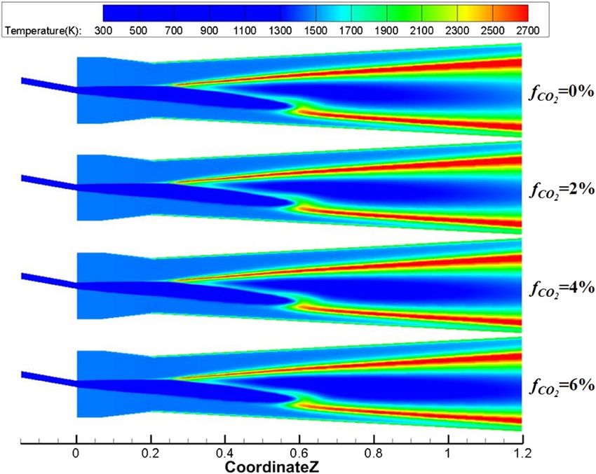
132 Juanjuan Jiang et al.
the lower part of the pulverized coal injection lance-blow- [16,17]; therefore, the RKE is used to simulate the com-
pipe-tuyere-raceway is established by using the numerical bustion of pulverized coal.
simulation method of the computational fluid dynamics.
The numerical simulation results guide the utilization of
CO2 in the ironmaking process.
2.3 Mathematical model of particle
discrete term
2 Mathematical model Eulerian–Lagrangian model is widely used to describe
the discrete phase, which can be used to parallel compu-
2.1 Computational models tation and discrete phase trajectory description. In this
paper, pulverized coal is regarded as the discrete phase
In this paper, the numerical simulation is performed and gas phase as the continuous phase, and the concen-
using commercial computational fluid dynamics software tration of pulverized coal is lower, which is in accordance
fluent 14.0, which is used to solve the Reynolds-averaged with the basic premise of the discrete phase model. The
Navier–Stokes (RANS) equation, the following is a mathe- equations of motion of particles in the Eulerian reference
matical expression of the RANS. frame are derived from the equilibrium of forces acting on
the particles. The effect of turbulent pulsation on parti-
∂ρ ∂
+ (ρui ) = 0 cles is described by the Random Walk Model. It is noted
∂t ∂Xi
that the motion of the discrete phase is not calculated in a
∂ ∂ fixed flow field, and the interaction between the discrete
(ρui ) + (ρui uj )
∂t ∂Xj phase and the continuous phase should be considered,
including momentum exchange, mass exchange, and
∂p ∂ ∂σij ∂σij 2 ∂σij
=− + σij + − σij energy exchange, its distribution law follows Newton’s
∂Xi ∂Xj ∂σij ∂σij 3 ∂σij
second law.
∂
+ (−ρui′ u′)
j d(up) (ρp − ρ) gi
∂Xj = FD(u − up) + + Fi
dt ρp
18μ CD Re
FD =
2.2 Gas-phase turbulence model ρp dp2 24
ρdp∣up − u∣
The turbulent model used in this paper is the k–ε model, Re =
μ
which includes the standard k–ε model (SKE), renorma-
lization k–ε model (RNG), and realizable k–ε model (RKE). The above formula assumes that the particle shape is
There are similar forms, which are based on the solution spherical, where ρ is the gas density, ρp is the pulverized
of k, ε transport equations. The main difference is the coal density, up is the pulverized coal velocity, u is the
method of solving turbulent viscosity, the turbulent continuous phase velocity, gi is the acceleration of gravity
trump number, and the emergence and integration of ε (i direction), Fi is the additional force on the pulverized
formulas. RNG and RKE models are proposed to improve coal particles in the direction i, FD(u − up) is the mass drag
the flow deficit in the swirl and turbulent models. In this force on pulverized coal particles, μ is the viscosity coef-
paper, RKE and standard wall function are used to simu- ficient, Re is the relative Reynolds number, and CD is the
late turbulent flow. The SKE is a semi-empirical model. drag coefficient.
To make the simulation result closer to the real experi-
ment, some parameters in the SKE need to be modified,
the RKE is developed to make up for the shortcomings
of the SKE in some applications. Compared with the SKE, 2.4 Mathematical model of pulverized coal
the RKE has two major differences: (1) the turbulent visc- combustion
osity is different and (2) the transport equation of the
dissipation rate is different. The results are in good agree- After the pulverized coal enters the blowpipe, it is heated
ment with the experimental data in previous studies by a high-speed hot blast and fastly passes the blowpipe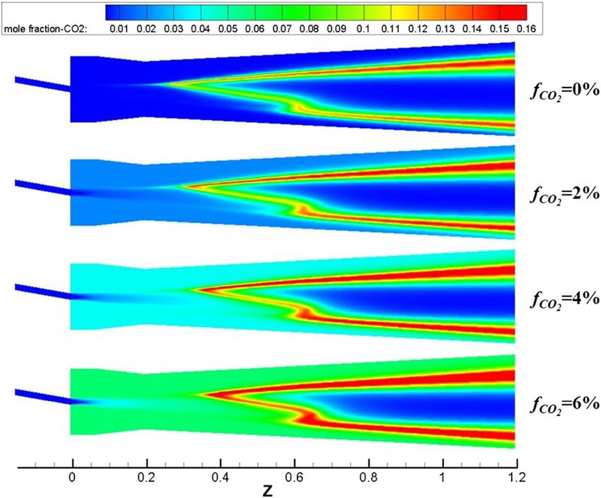
Effect of CO2 injection into blast furnace tuyeres 133
to enter the raceway zone to burn quickly. In this stage, E1 = 1.48 × 10⁸ J/mol, predigital factor A2 = 1.46 × 10¹³ s−1,
the pulverized coal is heated and burned in four pro- and activation energy E2 = 2.5 × 10⁸ J/mol.
cesses, as shown in Figure 1: (1) the moisture in the
pulverized coal evaporates, (2) the pulverized coal is pyro-
lyzed to remove the volatile matter, (3) volatile combus-
2.4.2 Volatile matter combustion model
tion, and (4) char combustion. In the simulation of fluent,
the above four processes are sequential, only after the
The key to the accurate simulation of turbulent combus-
previous phase has been completed, the next phase will
tion is the correct consideration of the relationship between
proceed. The wet combustion model is used for the simu-
turbulent flow and chemical reaction. The combustion
lation of the water evaporation process. The liquid matter
models in FLUENT include Laminar finite-rate (FR) model,
in the pulverized coal is set as liquid water, the percentage
Eddy-dissipation (ED) model, and Eddy-dissipation con-
of liquid water is set, and the gaseous matter volatilized
cept (EDC) model. The effect of turbulent fluctuation is
into the gas phase is set as water vapor.
neglected in the FR, and the reaction rate is controlled
by the Svante August Arrhenius expression. In the ED
model, it is assumed that the rate of reaction is controlled
2.4.1 Devolatilization model
by turbulent, so that a large number of Arrhenius che-
mical kinetics can be avoided; although this model is
In the devolatilization model, the surface temperature
computationally small, for the real situation, only one-
of pulverized coal rises rapidly and the devolatilization
or two-step heat release mechanism can be used and an
is removed by pyrolysis after the pulverized coal and
incorrect solution will be produced when multi-step reac-
low-temperature carrier gas enter the blowpipe and con-
tion mechanism is used. The EDC model is an extension
tact with the hot blast. In this paper, the two-competing-
of the ED model, in the EDC model, turbulent flames can
reactions model is used to describe the pyrolysis process
include detailed Arrhenius chemical kinetics, which is
of the pulverized coal. This model can describe the pyr-
highly reliable for simulating detailed chemical reaction
olysis reaction of pulverized coal under different reaction
mechanisms, and the model requires a large amount of
temperatures.
computation and high-computing resources.
K1
Raw coal ⟶ α1 VM1 + (1 − α1) Char1 R1 (low temperature) The EDC assumes that the chemical reaction takes
place on a small turbulent scale, commonly known as a
K2
Raw coal ⟶ α2 VM2 + (1 − α2) Char2 R2 (high temperature) fine scale and that the calculation of the components in
the simulation process is done after the chemical reaction
Rate of volatilization:
of the micro-scale has been completed. Comparing with
dVM other combustion models, the computation resources
= (α1 K1 + α2 K2) C0
dt and time required by the EDC are increased geometri-
In above formulas, where K1 and K2 are the devolatiliza- cally. In the EDC, only the reaction rate is considered
tion rates at different temperatures, α1 is the chemical and the mixing time is ignored at the micro-scale, which
equivalent coefficient of reaction, α2 = 1.25α12 + 0.92α1, is equivalent to a full stirrer. The model coupling turbu-
C0 is the mass of ash removal from pulverized coal, lent flow and chemical reaction through turbulent para-
predigital factor A1 = 3.7 × 10⁵ s−1; activation energy meters include turbulent kinetic energy and turbulent
dissipation rate. The size of a microscale ζ and the time
scale τ of a chemical reaction are defined as follows:
3/4
ξ = Cξ 2
vε
k
1/2
τ = Cτ
ν
ε
where Cξ is the volume fraction constant, 2.1377; ν is the
dynamic viscosity; and Cτ is the time scale constant, 0.4082.
In this simulation, the volatiles were simulated as
CH4, and a two-step chemical reaction model of methane
Figure 1: Basic process of pulverized coal combustion. was used (Table 1).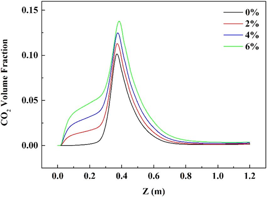
134 Juanjuan Jiang et al.
Table 1: Chemical kinetics parameters R5 : C(s) + H2 O = CO + H2
The reaction rate is expressed as follows:
Reaction Predigital Activation energy Reaction index
factor (kJ/mol) kr D0, r
Rj, r = Ap ηr Yj P
1 5.012 × 10¹¹ 2 × 10⁸ [CH4]0.7[O2]0.8
D0, r + kr
2 2.239 × 10¹² 1.7 × 10⁸ [CO][O2]0.25
[(Tp + Tg)/ 2]0.75
D0, r = Cj, r
dp
R1 : CH4 + 1.5O2 = CO + H2 O where Ap is the particle surface area, m2, ηr is the effective
R2 : CO + 0.5O2 = CO2 factor, Yj is the mass fraction of component j, P is the
partial pressure of the gas, Pa, Kr is the chemical kinetics
parameters, calculated by the Arrhenius equation, which
are listed in Tables 2 and 3, D0, r is the diffusion rate
2.4.3 Char yield combustion model
constant, and Cj, r is the molar concentration of a compo-
nent j in reaction r .
After all the volatiles have been precipitated, the fixed
carbon is oxidized and gasified. In general, heteroge-
neous reactions consist of the following basic steps:
2.5 Radiation model
(1) Gas molecules reach the solid surface by convection
and diffusion.
For the combustion of pulverized coal in enclosed space,
(2) The gas molecules are adsorbed on the solid surface.
the effect of thermal radiation cannot be neglected, and
(3) Elementary reactions of adsorbed molecules, solid
the radiation of pulverized coal particles, gas, and wall
surface itself, and various chemical reactions of gas-
surface needs to be considered. The P1 radiation model is
eous molecules.
a relatively simple model, which takes up less computa-
(4) Desorption of product molecules on the solid surface
tional resources and can take into account the radiation
(5) The product molecules leave the solid surface by con-
heat transfer between gas, wall, and particles, but its
vection and diffusion.
application is limited by the optical thickness and is
For the coke reaction, four heterogeneous surface
usually suitable for the case where the optical thickness
reaction models are provided by Fluent: the diffusion-
is more than 1 and the computational domain is large. In
limited rate model, the kinetic/diffusion-limited rate model,
contrast, the Discrete Ordinates model (DO) is much more
the intrinsic model, and the multiple surface reactions
complex and computationally intensive, but it can be
model. The diffusion-limited rate model is based on the
applied to all-optical thicknesses and can also simulate
assumption that the surface reaction process is controlled
the radiation of discrete terms. In this paper, DO is used
by the diffusion rate and the surface chemical kinetics
to describe the radiation model, the results are more
rate is ignored. The kinetics/diffusion-limited rate model
accurate.
assumes that the surface reaction is controlled either by
the diffusion rate or by the chemical kinetics rate. The
intrinsic model assumes that CO2 is produced directly by
the oxidation of coke and that the reaction rate is deter- 2.6 Other settings
mined by both the diffusion rate and the chemical
kinetics rate. The coke reaction model can only set a The solver uses a steady-state pressure base solver, and
part of the coke reaction; in contrast, the multi-surface the semi-implicit method for pressure linked equations
reaction model can set the multi-reaction of coke.
Since the variables in this model are the volume frac-
Table 2: Chemical kinetics parameters
tion of CO2 in the hot blast, the reaction between CO2 and
coke cannot be neglected. In this paper, a multi-surface Reaction Predigital Activation Temperature
reaction model is used. The reaction occurring on the factor energy (kJ/mol) coefficient
fixed carbon surface is as follows:
3 1.36 × 10⁶ 1.3 × 10⁸ 0.68
R3 : C(s) + 0.5O2 = CO 4 6.78 × 10⁴ 1.63 × 10⁸ 0.73
5 8.55 × 10⁴ 1.4 × 10⁸ 0.84
R4 : C(s) + CO2 = 2CO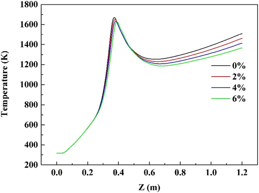
Effect of CO2 injection into blast furnace tuyeres 135
Table 3: Calculation of the operating mode entrance boundary furnace. The CO2 injection ratio is defined as CO2 enrich-
condition settings ment rate ( fCO2 ) which is the volume fraction of CO2 in the
hot blast.
Condition fCO2 in the hot Hot blast mass Carrier gas Figure 2 is a geometric model of the pulverized coal
blast (%) flow (kg/s) flow (kg/s)
injection lance-blowpipe-tuyere-raceway, the pulverized
1 (Datum) 0 1.9511953 8.162 × 10⁻³ coal injection lance with a diameter of 17.12 mm, an
2 2 1.9714122 8.162 × 10⁻³ angle of 10° with the axis of the model and an extension
3 4 1.9916292 8.162 × 10⁻³ of 150 mm, blowpipe with a diameter of 180 mm and
4 6 2.0118462 8.162 × 10⁻³ a length of 65 mm, tuyere with a length of 135 mm,
the diameter from 180 to 150 mm, and the raceway is
designed as a 3° divergent tube which can effectively
(SIMPLE) is used to solve all kinds of equations in the avoid the gas circulation, and the research focuses on
computational model. The algorithm uses the correction the flow and combustion behavior of pulverized coal in
relation between velocity and pressure to solve the mass the horizontal jet region under the raceway zone of the
conservation equation to obtain the pressure field, and blast furnace. According to the geometrical symmetry of
the relaxation factor remains the default. The global the model, the middle axis plane YZ is set as the sym-
average is used to initialize the computational domain. metry plane, and only 1/2 area of the model is simulated,
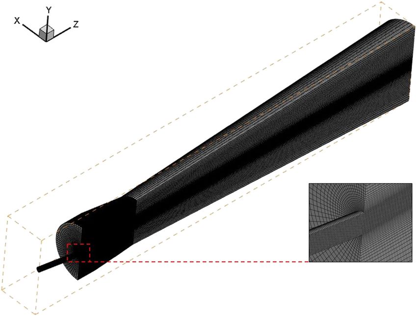
To improve the computational accuracy, in this paper, which can save computing resources and time. A sche-
the discrete numerical value of the second-order upwind matic diagram of the computational domain and grid of
scheme is used to calculate the equation. The In-Situ the model is shown in Figure 3; it also shows the compu-
Adaptive Tabulation (ISAT) proposed by Pope et al. is tational domain grid established by ICEM CFD.
used to speed up the computation.
The criterion of convergence is (1) mass conservation,
the difference of mass flow of all import and export
3.2 Boundary conditions
components in the computational domain is less than
10−8 kg/s; (2) the residual error of energy equation is
The temperature of the carrier gas (N2) of pulverized coal
less than 10−6, the residual error of other variables is
is fixed at 45°C, the pulverized coal and carrier gas enter
less than 10−5; and (3) set exit section CO gas volume
from the left side entrance of the pulverized coal injection
fraction and temperature detection section, exit section
lance and the entrance is set as mass flow entrance; the
temperature and CO gas volume fraction with iteration
hot blast uses oxygen-enriched air, which contains CO2
changes less than 1 K and 10−3.
and water vapor, and its temperature is fixed at 1,200°C,
the hot blast enters from the blowpipe and is set as mass
flow entrance; the raceway of the blast outlet is in a high-
pressure state, the outlet is set as the pressure outlet and
3 Geometry and operating the pressure is set as 350 kPa; and the wall surface of the
pulverized coal injection lance, blowpipe, and tuyere is
conditions
set as the adiabatic wall surface. Considering the hot coke
around the raceway, the wall surface temperature of the
3.1 Computational domain raceway is set as 2273.15 K. The variables in the whole
model calculation are fCO2 in the hot blast, which are 0,
The geometric model (3D) of this study is based on the 2, 4, and 6%, respectively. The specific parameters of
design and operation parameters of a 2,749 m3 blast inlet conditions are listed in Table 3. The mass flux of
Figure 2: A sketch of a geometric model (mm).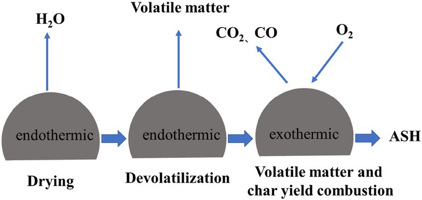
136 Juanjuan Jiang et al.
Figure 3: Schematic diagram of computational domain and grid of the model.
the hot blast in the table increases with the increase of phenomenon was found in the study by Zhang et al.
fCO2 in the hot blast because CO2 gas has replaced air, the [28] (Figure 5).
relative molecular mass of CO2 is larger than that of air,
and the mass flow rate increases when the volume flow
rate of the hot blast is constant. The mass flux of pulver-
ized coal is 1,250 kg/h, which is constant. The particle 4 Results and discussion
size distribution of pulverized coal is shown in Figure 4.
4.1 Effect on the temperature field
As shown in Figure 6, there are two high-temperature
3.3 Model validation
zones in the YZ plane temperature field of the furnace.
The location of the upper high-temperature zone is earlier
To verify the reliability and the independence of the model,
three meshes were selected, specifically, the encrypted
mesh (1,000,000 mesh), the normal mesh (630,000 mesh),
and the bold mesh 300,000 mesh); the model is used to
calculate the pulverized coal burnout rate under different
oxygen mass fractions in the blast. When the oxygen
mass fraction in blast increases from 25 to 30%, the pre-
decessors [26,27] found that the burnout rate increases by
approximately 4.5%. The simulation results show that
when the oxygen mass fraction in blast increases from
25 to 30%, the burnout rate specifically increases by 4.2,
4.18, 4.12%; it was found that the calculated results of the
three grids were close to the literature results. Therefore,
considering the availability and computational efficiency
of the grid, it was more suitable to select the common
grid as the simulation. In addition, the simulation results
show that the peak value of gas temperature on the
axis decreases with the increase of fCO2 . The same Figure 4: Particle size distribution of the pulverized coal.Effect of CO2 injection into blast furnace tuyeres 137
92 72
90.4
403
90 89.392 70
88.37
71
88 87.317
Burnout,%
68
Burnout,%
86.223
3
86
66
84
64
82
62
80
26 28 30
0 20 25 30
(a) Oxygen mass fraction in blast,% (b) Oxygen mass fraction in blast,%
Figure 5: Effect of oxygen mass fraction in the hot blast on pulverized coal burnout: (a) the results of this paper (the common grid) and
(b) literature results.
than that of the lower high-temperature zone. The main the heating of the hot blast, the temperature on the axis
reason is that the smaller pulverized coal is accumulated of the furnace began to rise; in the second stage, the
in the upper part of the furnace due to segregation, the temperature increases rapidly to the highest temperature,
combustion process is faster and the position of heat which is caused by the combustion of pulverized coal
release is earlier. With the increase of fCO2 in the hot blast, with smaller particle size; in the third stage, the tempera-
the overall temperature field in the furnace does not ture begins to drop, this is due to the heat absorbed
change much, and the high-temperature zones in the by the temperature rise of a large number of pulverized
furnace are similar, but the two high-temperature zones coal and devolatilization are greater than the volatile
gradually become thinner and the exit cross-section tem- matter and char yield combustion heat release; in the
perature decreases because of the heat absorption of CO2 fourth stage, this is due to the outside axis of the char
in the hot blast reacts with carbon. yield and volatile matter combustion heat release greater
Figure 7 is the curve of the temperature on the axis of than the temperature rise of pulverized coal and devola-
the furnace under different fCO2 in the hot blast. It is tilization the heat absorption. With the increase of fCO2 in
divided into four stages. In the first stage, because of the hot blast, the peak value of gas temperature on axis
decreases and moves back, the peak value drops because
Figure 6: Distribution of temperature field on YZ plane in a furnace Figure 7: The temperature curve on the axis of the furnace under
with different fCO2 in the hot blast. different fCO2 in the hot blast.138 Juanjuan Jiang et al.
of the heat absorption of CO2 in the hot blast reacts with
carbon. In the early stage of pulverized coal combustion,
pulverized coal heating, and volatilization are mainly
produced, which are highly affected by temperature.
The delay of pulverized coal combustion is caused by
the endothermic reaction of CO2 with carbon, and the
delay is more obvious with the increase of fCO2 .
4.2 Effect on the volume fraction of CO2
Figure 8 shows the distribution of the volume fraction
of CO2 in the YZ plane of the furnace under different
fCO2 in the hot blast. The concentration of CO2 in the Figure 9: The change curve of CO2 volume fraction on the axis of the
central region of the pulverized coal jet is relatively furnace under different fCO2 in the hot blast.
low. This shows that CO2 reacts with carbon mainly in
the central region of the pulverized coal jet. The higher fraction of CO2 drops to zero because of the lower con-
CO2 concentration in the outer region of pulverized coal centration of O2 on the central axis and all of the CO2 react
jet is due to the combustion of volatile matter and char with carbon.
yield, which is consistent with the temperature distribu-
tion in the furnace.
Figure 9 shows the change curve of CO2 volume frac-
tion on the axis of the furnace under different fCO2 in 4.3 Analysis of the burnout of
the hot blast. Overall, the change of CO2 volume fraction pulverized coal
can be divided into three stages. The first stage is a
slow-rising stage, which stage is mainly due to the diffu- In the evaluation of pulverized coal combustion perfor-
sion of CO2 gas along the axis in the surrounding hot mance, pulverized coal burnout is a non-dimensional
blast; the second stage is the stage of sharp rise which physical quantity to evaluate the quality of pulverized
is caused by the combustion of pulverized coal with coal combustion, which is essentially the gasification
smaller particle size; and in the third stage, the volume rate of combustible in pulverized coal. The value of
burnout reflects the gasification degree of pulverized
coal in the process of motion. The burnout of pulverized
coal can objectively measure the burnout characteristics
of pulverized coal and can be used as an evaluation index
to judge the performance of pulverized coal combustion
in the raceway of a blast furnace. Burnout is defined as
the mass change of a particle due to evaporation of water,
devolatilization, and combustion of volatile matter and
char yield, the formula is as follows:
ma,0
Burnout = 1 − (1 − ma,0)
ma
where ma,0 is the initial ash content in the pulverized coal
and ma is the ash content in pulverized coal.
As can be seen from Figure 10, with the increase fCO2
in the hot blast, the burnout of pulverized coal increases,
this is mainly because, with the increase fCO2 in the hot
blast, the oxidation of the hot blast increases, and CO2
Figure 8: Distribution of YZ plane CO2 volume fraction in a furnace gas can participate in the combustion reaction of char
with a different fCO2 rate in the hot blast. yield.Effect of CO2 injection into blast furnace tuyeres 139
Funding information: Authors state no funding involved.
Author contributions: The corresponding author is
responsible for ensuring that the descriptions are accu-
rate and agreed by all authors. The first author is respon-
sible for the topic selection, the formulation of the
research plan, the real-time research process, the data
collection and processing, and the drafting and revision
of the paper. The last author provides some key sugges-
tions for the writing of this paper.
Conflict of interest: Authors state no conflict of interest.
Data availability statement: The raw/processed data
required to reproduce these findings cannot be shared at
this time as the data also forms part of an ongoing study.
Figure 10: Pulverized coal burnout of outlet section under different
fCO2 in the hot blast.
References
5 Conclusions
[1] Boxun, H., G. Curtis, and L. S. Steven. Thermal, electro-
To find a new way to use CO2 as a resource in the metal- chemical, and photochemical conversion of CO2 to fuels and
lurgical industry on a larger scale, the effect of CO2 mixed value-added products. Journal of CO2 Utilization, Vol. 1, 2013,
pp. 18–27.
in the hot blast on the combustion behavior of pulverized
[2] Mahoutian, M., Z. Ghouleh, and Y. Shao. Carbon dioxide
coal was studied, a three-dimensional mathematical activated ladle slag binder. Construction and Building
model of pulverized coal flow and combustion in the Materials, Vol. 66, 2014, pp. 214–221.
lower part of the pulverized coal injection lance-blow- [3] Huijgen, W. J. J., G. J. Ruijg, R. N. J. Comans, and G. J. Witkamp.
pipe-tuyere-raceway was established. The conclusions Energy consumption and net CO2 sequestration of aqueous
are as follows: follows: mineral carbonation. Industrial and Engineering Chemistry
Research, Vol. 45, 2006, pp. 9184–9194.
(1) With the increase of fCO2 in the hot blast, the overall
[4] Zevenhoven, R., S. Eloneva, and S. Teir. Chemical fixation of
temperature field in the furnace does not change CO2 in carbonates: routes to valuable products and long-term
much, and the high-temperature zones in the furnace storage. Catalysis Today, Vol. 115, 2006, pp. 73–79.
are approximately similar, but the two high-tempera- [5] Weizao, L., A. Tahani, X. Chunbao, and L. Chun. Synthesis of
ture zones gradually become thinner. The heat absorp- sole gismondine-type zeolite from blast furnace slag during
tion of the CO2 in the hot blast reacts with carbon results CO2 mineralization process. Journal of Environmental Chemical
Engineering, Vol. 9, 2020, pp. 1046–1052.
in the decrease of the exit cross-section temperature.
[6] Han, Z., J. Gao, X. Yuan, and Y. Zhong. Microwave roasting
(2) The concentration of CO2 in the central region of the of blast furnace slag for carbon dioxide mineralization
pulverized coal jet is relatively low, which indicates and energy analysis. RSC Advances, Vol. 10, 2020,
that CO2 reacts with carbon mainly in the central pp. 17836–17844.
region of the pulverized coal jet. The concentration [7] Yi, Z., T. Wang, and R. Guo. Sustainable building material from
CO2 mineralization slag: aggregate for concretes and effect of
of CO2 on the central axis tends to zero at the exit,
CO2 curing. Journal of CO2 Utilization, Vol. 40, 2020, id. 101196.
because the concentration of O2 is relatively low, all [8] Zhizheng, L., Z. Rong, and M. Guohong. Laboratory investiga-
of the CO2 gas reacts with carbon. tion into reduction the production of dust in basic oxygen
(3) In the early stage of pulverized coal combustion, the steelmaking. Ironmaking and Steelmaking, Vol. 40, 2017,
delay of pulverized coal combustion is caused by pp. 601–608.
the endothermic reaction of CO2 with carbon, and the [9] Baochen, H., W. Guangsheng, and Z. Rong. Utilization of
carbon dioxide injection in BOF–RH steelmaking process.
delay is more obvious with the increase of fCO2 . In the
Journal of CO2 Utilization, Vol. 34, 2019, pp. 53–62.
later stage of pulverized coal combustion, the burnout [10] Ming, L., Z. Rong, and Y. Lingzhi. High efficiency depho-
of pulverized coal increases because of the increased sphorization by mixed injection during steelmaking process.
oxidation of hot blasts. Steel Research International, Vol. 90, 2019, id. 1800454.140 Juanjuan Jiang et al.
[11] Yunling, G., W. Haijuan, and Z. Rong. Study on experiment and [20] Ishii, K. Advanced pulverized coal injection technology and
mechanism of bottom blowing CO2 during the LF refining blast furnace operation. Pergamon, Oxford, UK, 2000.
process. Steel Research International, Vol. 85, 2014, [21] Yagi, J. Mathematical modeling of the flow of four fluids in a
pp. 589–598. packed bed. ISIJ International, Vol. 33, 1993, pp. 619–639.
[12] Baochen, H., Z. Rong, and Z. Yiqiang. Research on selective [22] Du, S. W., C. P. Yeh, and W. H. Chen. Burning characteristics of
oxidation of carbon and aluminum with introduction of CO2 in pulverized coal within blast furnace raceway at various injec-
RH refining of low-carbon steel process. Metallurgical and tion operations and ways of oxygen enrichment. Fuel, Vol. 143,
Materials Transactions, B, Vol. 49B, 2018, pp. 3544–3551. 2015, pp. 98–106.
[13] Wei, G., R. Zhu, and T. Tang. Study on the impact character- [23] Rangarajan, D., T. Shiozawa, and Y. Shen. Influence of oper-
istics of submerged CO2 and O2 mixed injection (S-COMI) in ating parameters on raceway properties in a model blast
EAF steelmaking. Metallurgical and Materials Transactions, B, furnace using a two-fluid model. Industrial and Engineering
Vol. 50, 2019, pp. 1077–1090. Chemistry Research, Vol. 53, 2014, pp. 4983–4990.
[14] Kuangdi, X. Low carbon economy and iron and steel industry. [24] Guo, B., P. Zulli, and H. Rogers. Three-dimensional simulation
Iron and steel, Vol. 3, 2010, pp. 1–12. of flow and combustion for pulverised coal injection.
[15] Agrawal, A., R. K. Tiwari, and S. Kumar. Technological ISIJ International, Vol. 45, 2005, pp. 1272–1281.
advancements in evaluating the performance of the pulverized [25] Wijayanta, A. T., M. S. Alam, and K. Nakaso. Combustibility
coal injection through tuyeres in blast furnace. Metallurgical of biochar injected into the raceway of a blast
Research and Technology, Vol. 117, 2020, pp. 611–633. furnace. Fuel Processing Technology, Vol. 117, 2013,
[16] Semenov, Y. S., V. V. Horupakha, and I. Shumelchik. Measures pp. 53–59.
for preventing disruption in the blast furnace operation under [26] Yansong, S., D. Maldonado, and G. Baoyu. Computational fluid
use of pulverized coal. Steel in Translation, Vol. 50, 2020, dynamics study of pulverized coal combustion in blast furnace
pp. 100–106. raceway. Industrial and Engineering Chemistry Research,
[17] Kawashima, T., A. Murao, and N. Yamamoto. Prediction of Vol. 48, 2009, pp. 10314–10323.
pulverized coal combustion behavior around tuyere by using [27] Yansong, S., G. Baoyu, Y. Aibing, and Z. Paul. Model study of
LES and extended CPD model. ISIJ International, Vol. 60, 2020, the effects of coal properties and blast conditions on pulver-
pp. 905–914. ized coal combustion. ISIJ International, Vol. 49, 2009,
[18] Yanjuan, J. Coal injection technology for blast furnace. pp. 819–826.
Metallurgical Industry Press, Beijing, 2005. [28] Zhang, S., Q. Xue, and J. Liu. Numerical simulation of pulver-
[19] Adrian, M. and R. Allan. Injection of pulverized coal and natural ized coal combustion in the raceway of an oxygen blast fur-
gas into blast furnaces for iron-making: lance positioning and nace. Chinese Journal of Engineering, Vol. 37, 2015,
design. ISIJ International, Vol. 55, 2015, pp. 1377–1383. pp. 638–647.You can also read


