Ceramic-to-Metal Joints Brazed with Palladium Alloys
←
→
Page content transcription
If your browser does not render page correctly, please read the page content below

Ceramic-to-Metal Joints Brazed
                             with Palladium Alloys
            Silicon nitride-to-nickel joints with shear strengths of 75 to 105 MPa
                at 200° and 500°C make heat engine applications a possibility

                                                BY J. H . SELVERIAN A N D S. K A N G

ABSTRACT. Several alloys containing             ing 650°C (1202°F). Palladium was              reported in wt-%) — Fig. 1. All of the
palladium were considered for use in            added to increase the melting point of         braze alloys except the 93Au-5Pd-2Ni
brazing ceramics to metals for heat en-         common ceramic-to-metal braze alloys.          alloy fall in a relatively straight line on
gine applications: 60Pd-40Ni, 30Au-             Silicon nitride is being considered for        liquidus surface of the Au-Pd-Ni ternary
34Pd-36Ni, 50Au-25Pd-25Ni, 70Au-                the ceramic component due to its high-         diagram (Ref. 2). There is a discrepancy
8Pd-22Ni, 93Au-5Pd-2Ni, and 82Au-               temperature strength and its thermal           between the liquidus of the braze alloys
18Ni (all in wt-%). Palladium filler n e t -    shock, oxidation, and creep resistance.        reported in this study (Table 1) and those
als were selected because of their o x i -      In this study, attention was focused on        from Fig. 1. The liquidus data presented
dation resistance, ductility and relatively     the reactions between the braze alloy,         in Table 1 are thought to be more accu-
high melting points. The reactions and          the coating and the silicon nitride.           rate, based on the discussion in Ref. 2.
microstructures were studied in experi-                                                           The Young's modulus (E), ultimate
mental brazed joints between silicon ni-        Procedure                                      tensile strength (err) and yield strength
tride and nickel. The joints brazed with                                                       (ay) of the alloys were measured with
the low-palladium alloys, 70Au-8Pd-                 The joint system contained a nickel        0.051 -mm (0.002-in.) thick dog bone-
2 2 N i , 93Au-5Pd-2Ni, and 82Au-18Ni,          substrate, a filler metal, and a silicon ni-   shaped foil samples —Table 1. The
had shear strengths of 75 to 105 MPa            tride ceramic. The silicon nitride con-        acoustic wave technique was used to
(11 to 1 5 ksi) from 20° to 500°C (68° to       tained 1 3 wt-% Y , 0 3 and 2 wt-% A l 2 0 3   measure Young's modulus of some
932°F). The joints brazed with the high-        as sintering aids, and was coated with 3       braze alloys that were available in bulk
palladium alloys, 60Pd-40Ni, 30Au-              p m of titanium, zirconium, or hafnium,        form. A strain gauge was used on the
34Pd-36Ni, and 50Au-25Pd-25Ni, all              w h i c h served to promote wetting be-        other samples to monitor the elongation
had shear strengths near zero. The na-          tween the braze alloy and silicon nitride.     to determine the Young's modulus. The
ture of the reactions and microstructure        The surface of the silicon nitride sub-        gauge length of the samples was 4.44
in the brazed joints will be discussed.         strates were polished, prior to surfacing,     cm long and 1.27 cm wide (1.75 X 0.5
                                                to a finish of 0.1 pm. Coatings were elec-     in.). These tensile samples were 1 0 cm
Introduction                                    tron beam evaporated onto the silicon          (4 in.) in length. The braze alloy foils
                                                nitride in a 1 0~3 Pa (1 0" 5 torr) vacuum     were vacuum annealed for 5 h at 900°C
   Ceramic-to-metal braze joints will ex-       at300°C(572°F).                                (1652°F) prior to testing. The 82Au-18Ni
perience great thermal and stress cycling          Five braze alloys containing palla-         braze alloy foil was vacuum annealed
when used in heat engines. The materi-          dium were studied: 60Pd-40Ni, 30Au-            for 5 h at 800°C (1472°F) due to its lower
als' system must withstand this cycling         34Pd-36Ni, 50Au-25Pd-25Ni, 70Au-               melting point.
and provide a reliable, creep-resistant         8Pd-22Ni and 93Au-5Pd-2Ni, along                  Wetting tests were performed by
and oxidation-resistant joint. The mate-        with 8 2 A u - 1 8 N i (all compositions are   melting braze alloy foil on T i - , Zr-, or
rials' system consists of the ceramic and                                                      Hf-coated silicon nitride substrates, in a
structural alloy materials, the filler metal,                                                  10"3 Pa vacuum. The wetting angle was
intermediate or compliant layers, and a                                                        recorded as a function of time.
coating on the ceramic. Intermediate                 KEY W O R D S                                A Hitachi RMU6-E magnetic sector
layers aid in accommodating the strains                                                        mass spectrometer attached to a vacuum
resulting from differential expansion be-                                                      tube furnace was used to measure the
tween the metal and ceramic compo-                    Ceramic-to-Metal Brazing
                                                                                               amount and type of residual gases in the
nents of the joint. Coatings on the ce-               Silicon Nitride Brazing
                                                                                               braze alloys and to monitor the reac-
ramic are necessary to promote wetting                Shear Testing                            tions occurring between the braze al-
and adhesion between the filler metal                 Palladium Braze Alloys                   loys and the coated silicon nitride. The
and ceramic (Ref. 1). Palladium-contain-              Gold Braze Alloys                        gases evolved from the sample were col-
ing filler metals were studied for ce-                Nickel Braze Alloys                      lected and emitted into the mass spec-
ramic-to-metal joints for use in heat en-             Ti Coatings                              trometer for analysis. The collection vol-
gines with service temperatures exceed-               Zr Coatings                              ume of the gases was 1.6 L and extended
                                                      Outgassing                               beyond the hot zone of the furnace.
J. H. SELVERIAN and S. KANG are with GTE              Heat Engines                             Since the vacuum gauge was mounted
Laboratories, Inc., 40 Sylvan Rd., Waltham,                                                    outside of the furnace hot zone, the pres-
Mass.                                                                                          sure measured was the gas pressure at

                                                                                       W E L D I N G RESEARCH SUPPLEMENT I 25-s
Table 1—Liquidus (TL) and Brazing (TB) Temperatures of the Braze Alloys, along with Selected Room-Temperature Mechanical Properties of the
Braze Alloy Foils, and the Room-Temperature Coefficient of Thermal Expansion (CTE).
Trade Name Au Pd Ni TL TB E G ffT ffy CTE
of Braze Alloy''" (wt-%) (°C) (°q (GPa) (GPa) u (MPa) (MPa) (X 1 0 - b / ° C )
Palni — 60 40 1238 1290 152.3 — — 585 448 —
Palniro 4 30 34 36 1169 1220 140.0 51.3 0.365 625 576 15.5
Palniro 1(c> 50 25 25 1121 1170 114.4 41.3 0.383 721 712 15.5
Palniro 7 70 8 22 1037 1090 114.0 41.1 0.388 644 572 17.5
Experimental16' 93 5 2 1082 1180 91.3 — — 187 115 —
Nioro (b) 82 — 18 950 1000 99.0 — — 744 592 17.5
(a) CTE WESGO, Belmont, Calif.
(b) Tensile properties w e r e measured from 0.002-in.-thick foil samples, a strain rate of 0.02 in./s, and the strain was measured with a strain gauge. Some of the foil samples failed prematurely by tearing.
(c) Young's Modulus, shear nodulus, and Poisson's ratio w e r e measured by the acoustic w a v e technique.
an unknown intermediate temperature ples brazed w i t h Au-5Pd-2Ni were brazed joint in the shear testing fixture
and was used only for comparing the heated 100°C (212°F) above the liquidus and the time to failure was recorded.
wetting tests of different samples. because the liquidus was incorrectly
The braze alloys were melted on a identified as 11 31 °C (2068°F). The sam- Results and Discussion
99.9% A l 2 0 3 substrate, to prevent reac- ples were furnace cooled, sectioned,
tions, to identify the residual gases in polished and examined in a scanning Wetting Behavior and Outgassing
the braze alloys. A sample was degassed electron microscope (SEM).
by heating to 400°C (752°F) for 1 0 min Joints between nickel and Ti-coated The results of the wetting tests on Ti-
in a cooler part of the tube furnace, then silicon nitride were brazed for shear test- coated silicon nitride are shown in Fig.
transferred into the furnace hot zone ing. A schematic of the shear test sam- 3A. All six braze alloys wet the Ti-coated
with a magnetic push rod. The furnace ples is shown in Fig. 2. Five shear tests silicon nitride w e l l , reaching a contact
was at the brazing temperature for the were conducted at room temperature angle of approximately 10 deg after 2
particular alloy under study. The same and at 500°C, in argon, for each of the min. In general, the reactions between
method was used to measure gases six braze alloys, for a total of 60 tests. the braze alloys and Ti-coated silicon
evolved during reactions between the Both the silicon nitride and nickel were nitride were moderate. The Ti coating
alloy and the Ti- and Zr-coated silicon 3 mm (0.1 2 in.) thick and the joint area was observed to react w i t h silicon ni-
nitride. (ignoring unbonded area) was 0.96 cm 2 tride to form TiN (Refs. 3-5).
Joints were brazed by ramping to the (0.15 in. 2 ). The same experimental set- Wetting tests were also performed on
brazing temperature (50°C/122°F above up used for shear testing was also used Hf- and Zr-coated silicon nitride sub-
the liquidus temperature) and holding to conduct stress-rupture tests at 500°C. strates. All of the braze alloys wet Hf-
for 5 min in a vacuum of 1 0" 3 Pa. Sam- A constant load was applied to the coated silicon nitride except the 60Pd-
40Ni braze alloy — Fig. 3B. During the
wetting tests on Hf-coated silicon ni-
tride, the Pd-containing braze alloys
bubbled, indicating that gas was
Au evolved. Severe gas evolution was also
seen for the Pd-containing braze alloys
Experimental Alloy on Zr-coated silicon nitride, and these
(93Au-5Pd-2Ni) wetting tests were not completed. Ap-
proximately 200 ppm of C O , C 0 2 and
Nioro H 2 were dissolved in each of the braze
(82Au-18Ni alloys, corresponding to 1 0"' Pa of gas.
The large amount of gas evolved during
some of the wetting tests could not be
explained by the comparatively small
amount of residual gas present in the
braze alloy foils.
A series of experiments designed to
study the interaction between braze al-
loys and coated silicon nitride were con-
ducted in a furnace/mass spectrometer
unit. Table 2 shows the results of these
investigations. Mass spectroscopy
showed that most of the samples gave
off hydrogen during the wetting tests.
Part of this hydrogen came from the
braze alloy itself. However, the major-
ity of the hydrogen was released from
the Ti and Zr coating w h e n part of the
coating was dissolved by the molten
Ni braze alloy. Titanium and zirconium are
Fig. I — The composition of the braze alloys used plotted on the liquidus surface of the ternary known to dissolve large amounts of hy-
Au-Pd-Ni phase diagram (wt-%). Liquidus surface is from Ref. 2. drogen.
26-s I J A N U A R Y 1992
The 60Pd-40Ni braze alloy released
a large amount of nitrogen during wet-
ting tests on both Ti- and Zr-coated sili-                                                                                   Si 3 N 4
con nitride. More nitrogen gas was
evolved when the braze alloys were                                                                                                 — -r •'.-»••-'•• - J Y j j V r ' V - J - , ' J Y - V - ' ' ' '

melted on Zr-coated silicon nitride as
compared to Ti-coated silicon nitride.
The difference in behavior between Ti-                                               Ni Substrate
and Zr-coated silicon nitride was unex-                                                                                                                                               Coating
pected since titanium and zirconium are
both Group IVB elements and have
many similar chemical characteristics.                                                                            Braze
    While the amount of nitrogen evolu-
tion appeared to depend on the palla-            Fig. 2 — Schematic of brazed coupons used for shear testing.
dium content of the braze alloys (Fig. 4),
the gas evolution was not caused by a
direct reaction between palladium and
                                                 Table 2—Mass Spectroscopy Results for Braze Alloy, Coating, Silicon Nitride Interactions in a
silicon nitride. Palladium does not re-
                                                 1.6 Liter Collection Volume
duce silicon nitride to form a palladium
silicide and nitrogen (Refs. 6, 7). The ni-
                                                                                                            Gas Pressure                         Test                                                   PN 2
trogen evolution when the 60Pd-40Ni                                                                           Pa X 102                        Temperature                                             Pa X 10 2
braze alloy wets Ti- or Zr-coated silicon        Sample                                                     (X 106 Torr)                                                                            (X 106 Torr)
                                                                                                                                                           (°q
nitride can be understood by the m i -
crostructure of the reaction zones.              Si,N4                                                      2.5 (193)                                     1300                                      2.0(154)
                                                 Ti-coated SitN4                                            0.17 (13)                                  1290                                      0.05 (4)
Microstructure                                   Zr-coated Si3N4                                            0.66 (50)                                     1290                                      0.33 (25)
                                                 (60Pd-40Ni)/Si3N4                                          3.2 (244)                                  1290                                      2.1 (159)
                                                 (60Pd-40Ni)/(Ti-coated Si3N4)                              2.2 (165)                                  1290                                      1.8(135)
    Joints were made between nickel sub-         (60Pd-40Ni)/(Zr-coated Si3N4)                              7.3 (553)
600
Table 3—Width of Brazed Region Measured
from the Gold X-Ray Map of Each Joint.
500 -
z Width of
Braze Alloy (Wt-%) Brazed Region TB TB-TL
tn Au Pd Ni (um) ;°q (°q
c Zr-coated silicon nitride
o 400 - 60 40 >60 1290 52
__ 30 34 36 20 1220 51
50 25 25 25 1170 49
o 70 22 40 1090 53
300 - 93 2
I 82 18
50
20
1180
1000
98
50
d>
_-. 200 -
tn
co c o n c e n t r a t i o n s of these e l e m e n t s . T h e r e
100 w a s a n i m p o r t a n t d i f f e r e n c e in t h e b e -
havior of the Ti coating and Zr coating
o n silicon nitride. The plateau regions
i n t h e n i t r o g e n a n d t i t a n i u m l i n e scans
on 10 20 30 40 50 (Fig. 6) i n d i c a t e t h a t t i t a n i u m r e a c t e d
w i t h the s i l i c o n n i t r i d e t o f o r m a 2 . 5 - p m -
t h i c k t i t a n i u m nitride layer, possibly
Pd in Braze Alloy, wt% c o m p o s e d of t w o forms of t i t a n i u m n i -
t r i d e . H o w e v e r , t h e lack o f a p l a t e a u re-
Fig. 4 — Plot of nitrogen partial pressure vs. palladium content of braze alloys for wetting of g i o n in the n i t r o g e n a n d z i r c o n i u m l i n e
braze alloys on Ti- and Zr-coated silicon nitride.
scans i n d i c a t e d t h a t t h e r e a c t i o n b e -
tween zirconium and silicon nitride was
a c t i o n i n v o l v e d d i s s o l u t i o n o f t h e base a c c o u n t e d for a s m a l l p e r c e n t a g e of the a dissolution of nitrogen into the z i r c o -
nickel by the molten braze alloys. The shear s t r e n g t h . nium without compound formation —
a m o u n t of d i s s o l u t i o n o f the n i c k e l w a s Reactions b e t w e e n the Ti c o a t i n g a n d F i g . 7. T h e Z r - r i c h r e g i o n w a s 1.8 p m
r e l a t e d t o a c o m b i n e d e f f e c t of h i g h Z r c o a t i n g w i t h t h e s i l i c o n n i t r i d e in w i d e in this j o i n t .
b r a z i n g t e m p e r a t u r e a n d the large s o l u - joints brazed w i t h the 5 0 A u - 2 5 P d - 2 5 N i The b u l k braze alloy regions of b o t h
b i l i t y of n i c k e l b y the b r a z e a l l o y . alloy w e r e e x a m i n e d w i t h an electron the T i - and Zr-coated silicon nitride
SEiVt images o f a j o i n t b r a z e d w i t h the m i c r o p r o b e analyzer (EPMA) e q u i p p e d joints brazed w i t h the 50Au-25Pd-25Ni
7 0 A u - 8 P d - 2 2 N i a l l o y are s h o w n in Fig. w i t h w a v e l e n g t h dispersive x-ray spec- alloy consisted of ternary A u - P d - N i
5. T h e g o l d a n d p a l l a d i u m w e r e u n i - t r o m e t e r s . These j o i n t s w e r e h e l d at t h e p h a s e s . L i t t l e s i l i c o n w a s seen i n t h e
f o r m l y d i s t r i b u t e d in t h e b r a z e d j o i n t . b r a z i n g t e m p e r a t u r e (11 7 0 ° C / 2 1 3 8 ° F ) braze alloy of the T i - c o a t e d silicon n i -
T h e series o f d a r k p a r t i c l e s near the i n - for 1 h to a l l o w a w i d e r e a c t i o n layer to tride joint. H o w e v e r , the joint w i t h the
terface in Fig. 5 A is a T i - N i phase. f o r m for easier analysis. Figures 6 a n d 7 Z r - c o a t e d s i l i c o n n i t r i d e h a d an a d d i -
Figure 5 A s h o w s signs of m e c h a n i c a l show t i t a n i u m , z i r c o n i u m and nitrogen tional phase present, a ternary silicide
i n t e r l o c k i n g at t h e b r a z e a l l o y / S i 3 N 4 i n - x-ray l i n e traces across t h e c o a t i n g / S i 3 N 4 w i t h an a p p r o x i m a t e c o m p o s i t i o n o f
terface. H o w e v e r , m e c h a n i c a l i n t e r l o c k - i n t e r f a c e . T h e s e l i n e traces are q u a l i t a - 39Ni-37Pd-24Si, determined by EMPA.
i n g w a s n o t w i d e l y e v i d e n t in t h e s e tive, and the ratio of the Ti and N sig- T h e larger n i t r o g e n partial pressure a n d
b r a z e d j o i n t s , a n d it is b e l i e v e d to h a v e nals is a c o m p l e x f u n c t i o n of t h e a c t u a l t h e s i g n i f i c a n t a m o u n t o f s i l i c o n in t h e
Fig. 5 — SEM images of brazed joint between nickel substrates and Ti-coated silicon nitride with the 70Au-8Pd-22Ni braze alloy. A — Backscat-
tered electron image; B — titanium x-ray map.
28-s I JANUARY 1992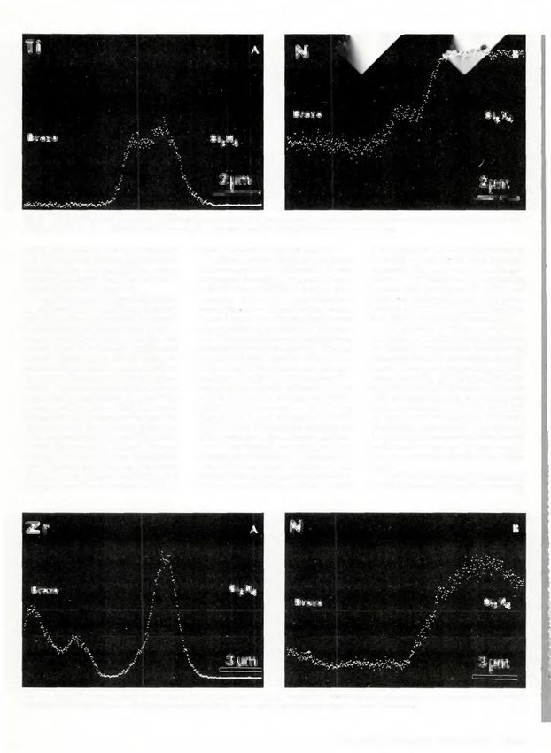
Fig. 6 — X-ray line scans across the Ti-coating/SijN4 interface in a joint between Ti-coated silicon nitride and nickel brazed with 50Au-25Pd-
25Ni alloy for I h. A — Titanium x-ray line scan; B — nitrogen x-ray line scan. The scan was 17.5 fim long.

braze alloy layer of the Zr-coated sili-         trogen bubbled off into the vacuum.               2. The effect of palladium appeared to
con nitride joints implied that the reac-            Different braze alloys on the same            be of slightly less significance, although
tion rate of the Zr-coated silicon nitride       substrate resulted in different amounts           important, in the amount of nitrogen
systems was faster than that of the Ti-          of nitrogen evolution. This was primar-           evolved. This was shown by comparing
coated silicon nitride systems.                  ily attributed to different reaction tem-         wetting tests carried out at 1 290°C on
    The difference in outgassing behav-          peratures since the high-palladium                Zr-coated silicon nitride with the 82Au-
ior between the Ti- and Zr-coated sili-          braze alloys have higher melting points.          18Ni (4.4 X 10~2 Pa N 2 ) and the 60Pd-
con nitride can be explained by the m i -        Figure 8 shows the nitrogen partial pres-         40Ni (6.6 X 10~2 Pa N2) braze alloys.
crostructures described above. When t i -        sure replotted as a function of tempera-             The behavior of the 93Au-5Pd-2Ni
tanium reacted with silicon nitride, one         ture. There was a strong correspondence           and 50Au-25Pd-25Ni braze alloys on
or two layers of a titanium nitride were         between temperature and PN 2 . The last           Zr-coated silicon nitride indicates the
formed. The titanium nitride layer pre-          four wetting tests listed in Table 2 clar-        synergistic effect of temperature and pal-
vented further reaction between the t i -        ify the effect of temperature on nitrogen         ladium content on nitrogen evolution —
tanium and braze alloy with the silicon          evolution. The 82Au-1 8Ni alloy on Zr-            Table 1 and Fig. 8. The 93Au-SPd-2Ni
nitride. However, when zirconium re-             coated silicon nitride released 4 X 1 0" 3        and 50Au-25Pd-25Ni braze alloys were
acted with silicon nitride, no zirconium         Pa (3 X 1 0-5 t o r r ) 0 f nitrogen at 1 000°C   held at essentially the same tempera-
nitride layer was formed (Ref. 8). We hy-        (1832°F) and released 4.4 X 1 0" 2 Pa             tures but evolved 1 . 7 X 1 0 - 2 and 5.5 X
pothesize that the reaction between the          (3.29 X 10"4 t o r r ) 0 f nitrogen at 1290°C     10"2 Pa (1.31 X 10'4 and 4.1 5 X 1 0"4 torr)
braze alloy and the Zr-coated silicon ni-        (2354°F). This indicates the significance         of nitrogen, respectively. The effect of
tride proceeded as follows: the silicon          of temperature on the nitrogen gas evo-           the interaction between temperature and
nitride decomposed, silicon diffused             lution. The effect of temperature on the          palladium content on nitrogen evolu-
through the zirconium layer and reacted          nitrogen evolution from Ti-coated sili-           tion was not clear and requires further
with the braze alloy forming the ternary         con nitride was minor, as shown by the            study.
silicide, some nitrogen dissolved in the         results of the same type of experiments
                                                                                                     The strong temperature dependence
zirconium, and the remainder of the ni-          run on Ti-coated silicon nitride — Table
                                                                                                   and the difference in reaction zones be-

Fig. 7 — X-ray line scans across the Zr-coating/Si'3N'4 interface in a joint between Zr-coated silicon nitride and nickel brazed with the 50Au-
25Pd-25Ni alloy for I h. A — Zirconium x-ray line scan; B — nitrogen x-ray line scan. The scan was 19 /um long.

                                                                                          W E L D I N G RESEARCH SUPPLEMENT I 29-s
600 T -I 1 l r-
The joints brazed w i t h the l o w - p a l l a -
d i u m alloys ( 7 0 A u - 8 P d - 2 2 N i , 9 3 A u -
Zr-coated
x 500
5Pd-2Ni, and 8 2 A u - 1 8 N i ) had the high-
est shear s t r e n g t h s . T h e a v e r a g e shear
tn Ti-coated
strengths at r o o m t e m p e r a t u r e w e r e 9 9 ,
c 77 a n d 8 2 M P a ( 1 4 , 1 1 , 1 2 ksi), respec-
o
400 tively, and w e r e 105, 85 and 104 MPa
__ ( 1 5 , 1 2 , 1 5 ksi) at 5 0 0 ° C , r e s p e c t i v e l y .
o The differences between the r o o m - t e m -
1 300
p e r a t u r e a n d 5 0 0 ° C shear s t r e n g t h s o f
the brazed joints were not statistically
d>
_- significant. H o w e v e r , the shear strengths
3 w e r e e x p e c t e d t o b e h i g h e r at 5 0 0 ° C
(A 200 t h a n at r o o m t e m p e r a t u r e d u e t o a re-
0)
d u c t i o n in r e s i d u a l stress in t h e s i l i c o n
a> n i t r i d e near t h e i n t e r f a c e . T h e r e s i d u a l
100 stress i n t h i s t y p e o f b r a z e d j o i n t w i t h
t h e 8 2 A u - 1 8 N i b r a z e is a p p r o x i m a t e l y
1 5 0 t o 2 0 0 M P a (22 t o 2 9 ksi) at r o o m
t e m p e r a t u r e (Ref. 1 1 ) . T h e larger r e s i d -
ual stress at r o o m t e m p e r a t u r e m a y ex-
1000 1100 1200 1300
p l a i n the larger standard d e v i a t i o n of the
j o i n t s t e s t e d at r o o m t e m p e r a t u r e as
Temperature, °C c o m p a r e d t o t h e j o i n t s tested at 5 0 0 ° C .
If m o r e shear tests w e r e c o n d u c t e d , it is
Fig. 8 — Plot of nitrogen partial pressure vs. reaction temperature of braze alloys for wetting felt that the e x p e c t e d d i f f e r e n c e b e t w e e n
of braze alloys on Ti- and Zr-coated nitride. the room-temperature and 500°C joint
strengths w o u l d b e c o m e statistically a p -
tween the Ti- and Zr-coated silicon ni- b e t w e e n the t i t a n i u m a n d t h e s i l i c o n n i - parent. T h e j o i n t s b r a z e d w i t h the 7 0 A u -
t r i d e substrates suggested that the d i f f u - t r i d e . H o w e v e r , in t h e Z r - c o a t e d s i l i c o n 8 P d - 2 2 N i a l l o y m a y be s l i g h t l y stronger
s i o n of n i t r o g e n t h r o u g h the T i N or z i r - n i t r i d e s a m p l e s , the z i r c o n i u m layer a l - than those brazed w i t h the 9 3 A u - 5 P d -
c o n i u m layer c o n t r o l l e d the reaction l o w e d for c o m p a r a t i v e l y r a p i d d i f f u s i o n 2 N i a l l o y at 5 0 0 ° C . M o r e t e s t i n g is r e -
rate a n d , t h e r e f o r e , t h e n i t r o g e n e v o l u - a n d a faster r e a c t i o n rate b e t w e e n z i r - quired before a definite statement can
t i o n . T h e diffusion coefficient o f nitrogen c o n i u m and silicon nitride. be m a d e .
in z i r c o n i u m at 1 2 9 0 ° C is 8.1 X 1 0 " 7
c m 2 / s w i t h an a c t i v a t i o n e n e r g y of 1 4 0 Mechanical Testing The W e i b u l l m o d u l u s of silicon n i -
k j / m o l e (Ref. 9). T h e r e f o r e , t h e r e a c t i o n t r i d e c e r a m i c used in this study w a s m e a -
between zirconium and silicon nitride Braze Alloy Foils. T h e t e n s i l e p r o p - sured by f o u r - p o i n t b e n d tests as 1 2. T h e
at 1 2 9 0 ° C s h o u l d e v o l v e a p p r o x i m a t e l y erties o f t h e a n n e a l e d b r a z e a l l o y f o i l s data f r o m the r o o m - t e m p e r a t u r e and
ten times more nitrogen than the same are listed in T a b l e 1 . A range of Y o u n g ' s 5 0 0 ° C shear tests o f t h e j o i n t s b r a z e d
r e a c t i o n w o u l d at 1 0 0 0 ° C , as s u p p o r t e d m o d u l i a n d y i e l d s t r e n g t h s are r e p r e - w i t h the 7 0 A u - 8 P d - 2 2 N i , 9 3 A u - 5 P d -
b y T a b l e 2. T h e d i f f u s i o n c o e f f i c i e n t o f sented b y these b r a z e a l l o y s . 2 N i , and 82Au-1 8 N i braze alloys were
n i t r o g e n in T i N is not k n o w n . H o w e v e r , Shear Tests. T h e results o f t h e r o o m - c o m b i n e d to calculate a W e i b u l l m o d -
as a n a p p r o x i m a t i o n , t h e d i f f u s i v i t y o f t e m p e r a t u r e a n d 5 0 0 ° C shear tests are ulus for these b r a z e d j o i n t s — Fig. 9. T h e
c a r b o n i n T i C w a s r e p o r t e d as 1 0 ~ ' ' t o s u m m a r i z e d i n T a b l e s 4 a n d 5. In m o s t W e i b u l l m o d u l u s was calculated to be
1 0""9 c m 2 / s w i t h an a c t i v a t i o n of 3 3 0 o f t h e 5 0 0 ° C tests, t h e n i c k e l substrate a p p r o x i m a t e l y 4 . T h e different tests w e r e
k j / m o l e (Ref. 1 0). W e h y p o t h e s i z e t h a t w a s slightly b e n t d u r i n g shear testing, c o m b i n e d since there was not a signifi-
t h e d i f f e r e n c e in b e h a v i o r b e t w e e n T i - w h i c h may have i n f l u e n c e d the m e a - cant difference between the different
a n d Z r - c o a t e d s i l i c o n n i t r i d e w a s d u e to sured s t r e n g t h v a l u e s . A l l o f t h e s i l i c o n j o i n t s a n d test c o n d i t i o n s . This c o m p o s -
t h e n a t u r e o f t h e d i f f u s i o n process. T h e nitride pieces were Ti-coated. Brazed i t e W e i b u l l m o d u l u s is n o t a n e x a c t
T i N l a y e r t h a t f o r m e d in t h e T i - c o a t e d joints w i t h Zr- a n d H f - c o a t e d s i l i c o n n i - v a l u e , since it c a m e f r o m different types
s i l i c o n n i t r i d e s a m p l e s a c t e d as a d i f f u - tride w e r e not tested d u e to the b u b b l i n g o f s a m p l e s ; h o w e v e r , it is a u s e f u l a p -
sion barrier and inhibited the reactions p r o b l e m discussed earlier. proximation. The brazing process
Table 4—Results from Room-Temperature and 500 C Shear Tests between Nickel Substrates and Ti-Coated Silicon Nitride.
Failure Load (kN)
Braze Alloy 25 =C 500°C)
Au Pd Ni Sampl e No. Sample No.
Wt-% 1 2 3 4 5 Ave. 4 5 Ave.
- 60 40 1.6 * * * * 1.6 2.6 4.4 3.2 0.8 * 2.8
0.4 3.3
30 34 36 0.2 0.5 * * * 3.3
*
50 25 25 * * * =. * *
70 8 22 9.9 7.1 6.4 7.6 18.5 6.8 9.3 10.0 10.5 11.6 9.2 9.9 11.7 7.6 9.4 10.6
93 5 2 6.9 4.2 10.4 8.2 7.7 8.4
4.7 7.3 9.5 10.0 8.7 8.0
82 - 18 5.5 2.5 7.4 10.2 24 12.8 13.7 10.9 7.3 10.0 8.6 12.3 11.9
7.9
' Indicates that the sample broke during handling and could not be tested.
— Indicates that no sample was brazed.
30-s I J A N U A R Y 1992
caused a substantial drop in the Weibull        Table 5—Shear Strengths from Room-Temperature and 500°C Shear Tests in Table 4
modulus of the silicon nitride in the
brazed joint. This decrease in Weibull                                                                                    Failure Shear Stress, MPa (ksi)
modulus was probably related to the
residual stress induced in the joint by                  Braze Alloy (Wt-%                                          25 >C                                       500 C
the coefficient of thermal expansion                  Au         Pd                    Ni               Mean>               Mean

Crack
Braze
Fig. 10 — Crack in shear test samples that forms on cooling. The
crack shown here did not propagate all the way through the silicon
nitride. However, the samples with this type of crack broke during Fig. 17 — Fracture surfaces from shear tested joints brazed with 30Au-
handling and could not be tested. 34Pd-36Ni (top) and 60 Pd-40Ni.
of Au-based braze alloys for high-tem- nitride layer but instead takes nitrogen A cknowledgmen ts
perature applications. The wetting be- into solid solution, releasing the nitro-
havior of these alloys and T i - , Zr- and gen, and is more reactive w i t h the sili- This research was sponsored, in part,
Hf-coated silicon nitride was also stud- con nitride. by the U.S. Department of Energy, As-
ied. All of the braze alloys wet the Ti- Joints brazed w i t h the high-palla- sistant Secretary for Conservation and
coated silicon nitride w e l l . However, dium alloys also had the lowest room- Renewable Energy, Office of Transporta-
problems were encountered w i t h the temperature and 500°C shear strengths tion Systems, as part of the Ceramic
high-palladium alloys (60Pd-40Ni, and consistently resulted in poor joint Technology for Advanced Heat Engines
50Au-25Pd-25Ni and 30Au-34Pd- Project of the Advanced Materials De-
quality. Joints brazed with the low-pal-
velopment Program, under contract DE-
36Ni) on the Zr and Hf coatings. Bub- ladium alloys had good shear strengths
AC05-840R21400 with Martin Marietta
bling of the molten braze alloy was ob- at room temperature and 500°C: 75 to
Energy Systems, Inc.
served. This bubbling was attributed to 1 00 MPa (11 to 1 4 ksi) and 85 to 1 05
the different reactions between the Ti The participation in the experimen-
MPa (12 to 15 ksi), respectively. The
tal program by Dan Bazinet and Glenn
coating and Zr coating with the silicon brazing process damaged the silicon ni-
M c C l o u d is gratefully acknowledged.
nitride. Titanium reacts with silicon ni- tride to a large extent, and the Weibull
Assistance from the Materials Charac-
tride to form a titanium nitride layer. modulus of the silicon nitride decreased
terization Department, particularly from
Z i r c o n i u m does not form a z i r c o n i u m from 1 2 to 4. Dan Oblas, George Werber, Jody Har-
ris and Jesse Hefter, was much appreci-
1000 l . nrrr, I l-lll.ni i ated.
. . References
•
• 70Au-8Pd-22Ni '.
1. Santella, M. 1988. Brazing of titanium-
• 82Au-18Ni
: vapor-coated silicon nitride. Advanced Ce-
ramic Materials 3 (5):457-462.
2. Prince, A., Raynor, G. V., and Evans,
•
Q.
•
D. S. 1990. Phase diagrams of ternary gold
alloys, p. 322. London, England, The Insti-
tute of Metals.
tn 100 -- • - 3. Kang, S., Dunn, E. M., Selverian, J. H.,
tn and Kim, H. |. 1989. Issues in ceramic-to-
d> . . metal joining: an investigation of brazing a
i— silicon nitride-based ceramic to a low-expan-
CO
•
•
—****5* •
•
sion superalloy. American Ceramic Society
_.u/fef/n68(9):1608-I617.
•
4. Barbour, ). C, Kuiper, A. E. T., Willem-
• """"-'--^^ sen, M. F. C, and Reader, A. H. 1987. Thin-
film reaction between Ti and Si 3 N 4 . Applied
Physics Letters 50(15):953-955.
5. Morgan, A. E., Broadbent, E. K., and
1 I I I I nil l Sadana, D.K.I 986. Reaction of titanium with
10
.01 .1 1 10 100 1000 silicon nitride under rapid thermal annealing.
Applied Physics Letters 49 (19):1236-1238.
6. Chart, T. C. 1973. Thermochemical
Time, Hrs data for transition metal-silicon systems. High
Temperatures - High Pressures 5:241-252.
Fig. 12 — Results from 500° C stress rupture tests of joints brazed with the 70Au-8Pd-22Ni 7. Kubaschewski, O., and Alcock, C. B.
and 82Au-l8Ni braze alloys. 1979. Metallurgical Thermochemistry, p.
32-s I JANUARY 1992
310. New York, N.Y., Pergamon Press.                O n the diffusion of carbon in titanium carbide.     Development of new active filler metals in a Ag-
    8. Tomsia, A. P., and Loehman, R. E. 1990.      Metallurgical Transactions A 20A(3):403-411.         Cu-Hf system. Welding Journal 69(11 ):41 6-s to
Reaction mechanisms in active metal braz-                1 1 . Kang, S., Selverian, J. H., Kim, H.,      421-s.
ing. Proc. of the 92nd Amer. Ceram. Soc. An-        O ' N e i l , D., and Kim, K. 1990. Analytical and       1 3. Evans, A. G., Dalgleish, B. J., He, M „
nual Meeting, Abstract 246.                         experimental evaluation of joining silicon ni-       and Hutchinson, I. W. 1989. On crack path se-
    9. Mangio, C. A. 1955. Diffusion: the met-      tride to metal and silicon carbide to metal for      lection and the interface fracture energy in bi-
allurgy of z i r c o n i u m . B. Lustman and F.    advanced heat engine applications. Depart-           material    systems.     Acta       Metallurgica
Kerze, jr., eds., p. 422, New York, N.Y., Mc-       ment of Energy Contract N o . DE-AC05-               37'(12):3249-3254.
Graw-Hill.                                          840R21400.
    10. van Loo. F.). J., and Bastin, G. F. 1989.        1 2. Lugscheider, E., and Tillman, W. 1990.

                                                         WRC Bulletin 360
                                                          January 1991
            Stress Indexes, Pressure Design and Stress Intensification Factors
            for Laterals in Piping
            By E. C. Rodabaugh
                The study described in this report was initiated in 1987 by the PVRC Design Division Committee on Piping,
            Pumps and Valves under a PVRC grant to E. C. Rodabaugh following an informal request from the ASME Boiler
            and Pressure Vessel Committee, Working Group on Piping (WGPD) (SGD) (SC-II) to develop stress indexes and
            stress intensification factors (/-factors) for piping system laterals that could be considered by the ASME Commit-
            tee for incorporation into the code.
                In this study, the author has considers all existing information on lateral connections in concert with existing
            design guidance for 90-deg branch connections; and has developed compatible design guidance for lateral con-
            nections for piping system design. As a corollary bonus, he has also extended the parameter range for the "B"
            stress indexes for 90-deg branch connections from d/D = 0.5 (the present code limit) to d/D = 1.0. Therefore,
            this report should be of significant interest to the B31 industrial piping code committees, as well as the ASME
            Boiler and Pressure Vessel Committee.

               Publication of this bulletin was sponsored by the Committee on Piping, Pumps and Valves of the Design Divi-
            sion of the Pressure Vessel Research Council. The price of WRC Bulletin 360 is $30.00 per copy, plus $5.00 for
            U.S. and $10.00 for overseas, postage and handling. Orders should be sent with payment to the Welding Re-
            search Council, Room 1301, 345 E. 47th St., New York, NY 10017.

                                                         WRC Bulletin 363
                                                           May 1991
            Recommended Practices in Elevated-Temperature Design: A Compendium
            of Breeder Reactor Experiences (1970-1987), Volume II—Preliminary
            Design and Simplified Methods
            Edited by A. K. Dhalla
                 The recommended practices for elevated-temperature design of liquid metal fast breeder reactors (LMFBR)
            have been consolidated into four volumes to be published in four individual WRC bulletins.
                 Volume I: Current Status and Future Directions (WRC Bulletin 362)
                 Volume II: Preliminary Design and Simplified Methods (WRC Bulletin (363)
                 Volume III: Inelastic Analysis (WRC Bulletin 365)
                 Volume IV: Special Topics (WRC Bulletin 366)
                 In Volume II, preliminary design procedures are described that provided practical design and analysis guide-
            lines for specific structural design problems encountered in the past. Also included is a detailed discussion of sim-
            plified methods to support both preliminary and final design evaluations.

               Publication of this bulletin was sponsored by the Committee on Elevated Temperature Design of the Pressure
            Vessel Research Council. The price of WRC Bulletin 363 is $40.00 per copy, plus $5.00 for U.S. and $10.00 for
            overseas, postage and handling. Orders should be sent with payment to the Welding Research Council, Room
            1301, 345 E. 47th St., New York, NY 10017.

                                                                                                WELDING RESEARCH SUPPLEMENT I 33-s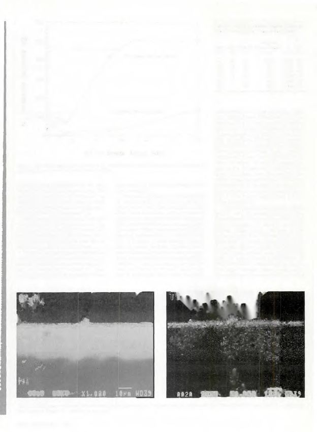
First Announcement and
                                Call for Papers

              1992 NORTH AMERICAN
           WELDING RESEARCH CONFERENCE
            RECENT DEVELOPMENTS IN THE JOINING OF
               STAINLESS STEELS AND HIGH ALLOYS

                        Columbus, Ohio, October 19-21, 1992
                              Hyatt on Capitol Square

      The Eighth Annual North American Conference on Welding Research
      w i l l provide a state-of-the-art review of recent developments and
      advances in the joining technology for stainless steels, including
      austenitic and "super" austenitic, duplex and "super" duplex, ferritic,
      martensitic and specialty grades, and high alloy Ni-base and Co-base
      alloys used in corrosive and/or high temperature applications.

      Papers are sought in the following areas:

             •   Welding metallurgy
             •   Welding process development (arc and HED processes)
             •   Welding process development (solid state processes)
             •   Weld properties
             •   Design and Fitness-for-Service
             •   Corrosion behavior
             •   Total Quality Joining

      For more information on the technical content of the conference,
      contact:
                               Dr. John Lippold
                               Manager, Research Development
                               EWI
                               1100 Kinnear Road
                               Columbus, Ohio, USA 43212
                               Phone (614) 486-9400, FAX (614)486-9528

34-s I JANUARY 1992
You can also read