LION: Lidar-Inertial Observability-Aware Navigator for Vision-Denied Environments - arXiv
←
→
Page content transcription
If your browser does not render page correctly, please read the page content below
LION: Lidar-Inertial Observability-Aware
Navigator for Vision-Denied Environments
Andrea Tagliabue∗,1 , Jesus Tordesillas* ,1 , Xiaoyi Cai* ,1 , Angel
Santamaria-Navarro2 , Jonathan P. How1 , Luca Carlone1 , and Ali-akbar
Agha-mohammadi2
Abstract State estimation for robots navigating in GPS-denied and perceptually-
degraded environments, such as underground tunnels, mines and planetary sub-
surface voids [1], remains challenging in robotics. Towards this goal, we present
LION (Lidar-Inertial Observability-Aware Navigator), which is part of the state es-
timation framework developed by the team CoSTAR [2] for the DARPA Subter-
ranean Challenge [3], where the team achieved second and first places in the Tunnel
arXiv:2102.03443v1 [cs.RO] 5 Feb 2021
and Urban circuits in August 2019 and February 2020, respectively. LION provides
high-rate odometry estimates by fusing high-frequency inertial data from an IMU
and low-rate relative pose estimates from a lidar via a fixed-lag sliding window
smoother. LION does not require knowledge of relative positioning between lidar
and IMU, as the extrinsic calibration is estimated online. In addition, LION is able
to self-assess its performance using an observability metric that evaluates whether
the pose estimate is geometrically ill-constrained. Odometry and confidence esti-
mates are used by HeRO [4], a supervisory algorithm that provides robust estimates
by switching between different odometry sources. In this paper we benchmark the
performance of LION in perceptually-degraded subterranean environments, demon-
strating its high technology readiness level for deployment in the field.
Video: https://youtu.be/Jd-sqBioarI
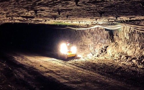
Fig. 1: Ground robots using LION to explore the Arch Coal Mine (West Virginia, USA), at ap-
proximately 275 meters (900 feet) underground.
1
Massachusetts Institute of Technology, Cambridge, MA e-mail: {atagliab,jtorde,xyc,
jhow,lcarlone}@mit.edu
2
Jet Propulsion Laboratory, California Institute of Technology, Pasadena, CA e-mail: {angel.
santamaria.navarro,aliagha}@jpl.nasa.gov This research work was partially car-
ried out at the Jet Propulsion Laboratory, California Institute of Technology, under a contract with
the National Aeronautics and Space Administration. Government sponsorship acknowledged.
∗
These authors contributed equally
1
2                                                  A. Tagliabue, J. Tordesillas, X. Cai et al.

1 INTRODUCTION

Accurate and efficient odometry estimation for motion planning and control of
robots in GPS-denied, perceptually-degraded, unknown underground environments
still remains challenging in robotics. Common visual and visual-inertial solutions
[5–8] are not suitable for this task due to the potential absence of light or the strong
illumination changes caused by mounting a light source on a moving robot. State
estimation strategies for these environments [9, 10] usually rely on proprioceptive
sensing (e.g., IMU, wheel-encoders) and/or active exteroceptive methods (e.g., li-
dar, SoNaR, Time-of-Flight cameras or ultrasonic sensors). To compute odometry
estimates in subterranean environments, the robots of the team CoSTAR relied on
the complementarity of a lidar and an IMU as preferential sources of information.
    Lidar odometry (LO) and Lidar-Inertial odometry (LIO) present multiple chal-
lenges, especially related with the trade-offs between estimation accuracy and com-
putational complexity, and scene observability. Most of the current approaches com-
pute lidar odometry via the Iterative-Closest Point (ICP) algorithm [11–15] or
by extracting and matching features [16–18]. While the first approach is gener-
ally less computationally expensive, the second is more practical for the purpose
of creating a sparse map used for efficient re-localization. In both cases, the odom-
etry estimates can be refined by aligning lidar-scans or lidar-features with a local
map [16, 18]. Fusing the information from an IMU generally improves the estima-
tion accuracy [17, 19–21], since it further constrains the estimate and guarantees a
high-output rate, thanks to techniques such as IMU pre-integration [22]. Regardless
of the scan-alignment technique used, lidar-based methods produce poor estimates
in those scenarios that are not sufficiently geometrically-rich to constrain the mo-
tion estimation [23–25]. This is especially true in tunnel-like environments [9, 10],
where it is not easy to constrain the relative motion along the main shaft of the
tunnel. Techniques employed to mitigate these issues consist of observability-aware
point-cloud sampling [23], degeneracy detection and mitigation [24, 26, 27] and the
fusion of other sources of information, such as inertial data from an IMU.
    This work presents LION, a Lidar-Inertial Observability-Aware algorithm for
Navigation in perceptually-degraded environments, which was adopted by the team
CoSTAR for the first year of the DARPA Subterranean Challenge. Our solution re-
lies on the fusion of pre-integrated IMU measurements [22] with pose estimates
from scan-to-scan ICP alignments, taking advantage of a fixed-lag smoother archi-
tecture [28, 29]. We simultaneously calibrate online the extrinsics (translation and
rotation) between the lidar and IMU sensors. To address potential observability is-
sues, we use a geometric observability score [23] that allows LION to predict poten-
tial degradation in its output given the geometric structure of the observed scene. By
reporting the proposed score, we can switch to a different state estimation algorithm
(e.g., from wheel encoders, visual-inertial or thermal-inertial) via a supervisory al-
gorithm, such as HeRO [4]. This approach guarantees a continuous, reliable and
gravity-aligned state estimate to the cascaded planning and control algorithms [30].
    LION has been extensively tested in two coal mines of Beckley (West Virginia),
two NIOSH experimental mines in Pittsburgh (Pennsylvania), a gold mine in Idaho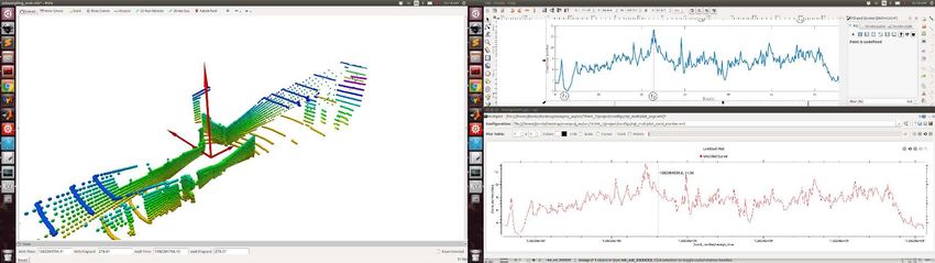
lion-system-diagram.drawio                                                                                                            https://www.draw.io/

         LION: Lidar-Inertial Observability-Aware Navigator                                                                                                       3

                                                         LION
            Sensors                    Front-End

                                                                        observability_check
                                        Observability
                                          Detector

                                                                                                          Switching Logic
                                                                          Back-End

                                           Lidar        relative_pose
            Lidar
                      pointcloud_meas    Odometry
                                                                         Factor-Graph
                                                                                              odometry
                                                                         Optimization
                                                                          (Fixed-Lag
                                                                          Smoothing)
                                          IMU Pre-
             IMU
                       acc_gyro_meas     Integration      pim_meas

         Fig. 2: Front-end and back-end of LION. The                                                                        Fig. 3: Factor graph representing state
         front-end runs ICP and IMU pre-integration,                                                                        and measurements used by LION. In
         whose outputs are used as factors in the back-                                                                     this figure we use the shortcut bj :=
         end pose-graph optimization                                                                                        {ba ,B bg }j for the biases.

         Springs (Colorado), and many office-like environments at the Jet Propulsion Labo-
         ratory (California), showing its high readiness level for deployment in the field.

         2 TECHNICAL APPROACH

         Lidar-Inertial Odometry: LION is a sliding window estimator divided into two
         parts: a front-end consisting of the lidar-odometry and IMU pre-integration, and a
         factor-graph back-end (see Fig. 2). In the following, we use an odometry reference
         frame W , a body reference frame B, attached to the center of the IMU, and the lidar
         frame L, attached to the center of the lidar. The rigid transformation from a point
         expressed in a frame A to a point expressed in frame B is represented as the 4 × 4
         matrix B TA , which contains the rotation matrix B RA and translation vector B tA .
            The front-end of LION consists of three modules: lidar odometry, IMU pre-
         integration and the observability detector (see section 2). The lidar odometry mod-
         ule obtains relative pose measurements Lk−1 TLk by using the Generalized Iterative
1 of 1
         Closest Point algorithm [31] on two lidar point clouds captured         from consecutive
                                                                       6/30/20, 12:23 AM
         lidar frames Lk and Lk−1 at time stamps k and k − 1 respectively. To ease the
         convergence of the ICP algorithm, every incoming point cloud is pre-rotated in a
         gravity aligned-frame (i.e., setting the rotation estimated by the IMU as initial guess
         for ICP). The IMU pre-integration module leverages the state-of-the-art on-manifold
         pre-integration theory to summarize the high-rate IMU measurements into a single
         motion constraint [22, 32]. Alternatively, the scan-to-scan based front-end can be
         replaced by LOCUS [33], which additionally aligns the incoming scan to an incre-
         mentally built local map and performs a refinement step.
            In the back-end, the relative pose measurements produced by the front-end are
         stored in a factor graph in conjunction with the IMU measurements. A representa-
         tion of the states and factors used in the factor graph can be found in Fig. 3. Let us
         define the state vector xj at the j-th time step as
                                                                                                                 a     g
                                                        xj := { W TB ,                                   W v, B b , B b , B TL }j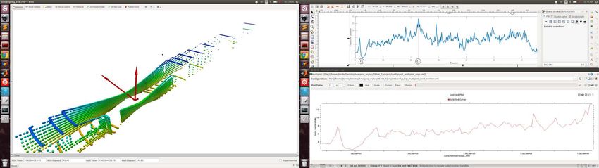
4                                                   A. Tagliabue, J. Tordesillas, X. Cai et al.

where W TB is the IMU-to-world transformation, W v is the linear velocity, B ba
and B bg are the accelerometer and gyroscope biases of the IMU, and B TL is the
lidar-to-IMU transformation. Following the notation from [32], let Kk := {k − m +
1, ..., k} denote the m time steps inside the sliding window, and let Xk := {xj }j∈Kk
and Zk denote respectively the states and measurements in this sliding window. The
factor graph optimization aims to solve therefore the following program [32]: Xk? :=
arg minXk (− loge p (Xk |Zk )), where p (Xk |Zk ) is the posterior distribution. We
model the optimization problem using GTSAM [29] and solve this optimization
problem using iSAM2 [28].
    Observability Metric: In subterranean environments, it is crucial for a state es-
timation algorithm to determine how well the geometry of the scene is able to con-
strain the estimation in all the translational directions. Following [23, 34], and as-
suming that the rotation is small, the Hessian
                                                of thePoint-To-Plane ICP cost is given
                       PM       >           Arr Art
by 2A, where A := i=1 Hi H i :=                          , Hi := [−(pi × ni )> , −n>  i ],
                                            A> rt A  tt
and ni is the surface unit normal vector based at a point pi . The eigenvector asso-
ciated with the smallest eigenvalue of A is the least observable direction for pose
estimation. The translational part is usually the most challenging part of the pose to
estimate, mainly because of the presence of long shafts and corridors. We propose
therefore to use the condition number κ(Att ) := |λ        max (Att )|
                                                        |λmin (Att )| as the observability
metric. The larger the condition number κ(Att ) is, the more poorly constrained
the optimization problem is in the translational part. When this condition number
is above a user-defined threshold, LION issues a warning to the switching logic
HeRO [4], so that other more reliable odometry sources can be used.

3 EXPERIMENTAL RESULTS

3.1 LION estimation performance in the 2019 Tunnel competition

We first evaluate the performance of LION (translation and rotation errors, and re-
peatability of the results) in the two runs of the two different tracks of the Tun-
nel Competition, held in the NIOSH experimental mines in Pittsburgh, USA. Lidar
odometry was computed at 10 Hz, while IMU and LION output could be provided
at up to 200 Hz. The sliding window of LION used is 3 seconds and LION back-end
was tuned to use approximately 30% of one CPU core of an i7 Intel NUC. For refer-
ence, we compare its performance with Wheel-Inertial odometry (wheel odometry
fused with an IMU via an Extended Kalman Filter) and Scan-To-Scan odometry
(the relative pose input of LION), with LAMP [35] as ground truth.
    The results are summarized in Table 1. We can see that fusing inertial data with
the odometry from the front-end (LION) significantly reduces the drift of the pure
lidar-odometry method (Scan-To-Scan). This is especially evident from the estima-
tion error along the z-axis shown in Fig. 4. Additionally, LION reliably estimates
the attitude of the robot (Fig. 5), achieving small roll and pitch errors (since they are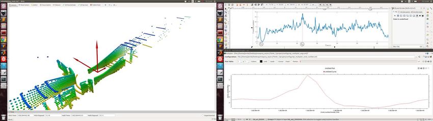
LION: Lidar-Inertial Observability-Aware Navigator                                              5

Fig. 4: Position estimation RMSE. (Track A,      Fig. 5: Attitude estimation RMSE. (Track A,
Run 2)                                           Run 2)

              START

Fig. 6: x, y position estimates. (Track A, Run   Fig. 7: Estimation of the translation of the ex-
2, first 1000 s)                                 trinsics.

observable in the IMU via the gravity vector) and yaw. Fig. 6 shows that LION out-
performs the baseline approach (Wheel-Inertial) especially in terms of drift in yaw
and horizontal translation. To showcase LION’s auto-calibration capabilities, we
generate in simulation a dataset where the lidar is translated of 0.1 m with respect
to the IMU, along the IMU’s y-axis. In Fig. 7 we observe that after approximately
20 s, LION (continuous lines) estimates the correct extrinsics (dotted lines). Last,
we compare LION with the state-of-the-art method LOAM [18]. The comparison,
shown in Fig. 4, 5 and 6 and Table 1, highlights that LION performs comparably
to LOAM for short trajectories (t < 600 s in Fig 4, and Table 1, Track B, Run
2), while LOAM (thanks to the presence of a map which compensates for drifts)
achieves lower position and yaw drift for longer trajectories. LION obtains compa-
rable or slightly lower roll and pitch errors thanks to the fusion of IMU data (Fig.
5), which guarantees a gravity-aligned output provided at IMU rate. The output rate
of LOAM is instead limited to the rate of the lidar.

3.2 Observability module

We first show how the condition number can detect geometrically-unconstrained
scenes. To test this and to build intuition, we first use the dataset JPL-Corridor,
recorded in an office at JPL, whose main challenge is the lack of geometric features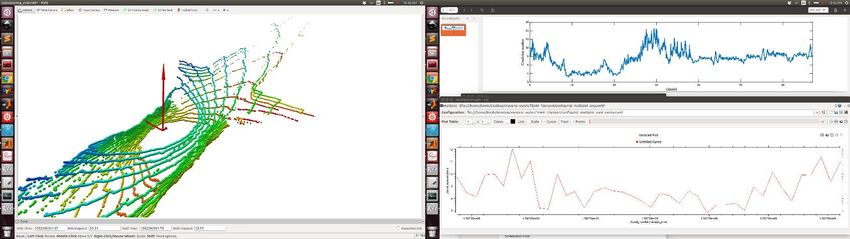
6                                                            A. Tagliabue, J. Tordesillas, X. Cai et al.

                                Track A                                      Track B
               Run 1 (685 m, 1520 s) Run 2 (456 m, 1190 s)   Run 1 (467 m, 1452 s) Run 2 (71 m, 246 s)
 Algorithm      t(m) t(%) R(rad) t(m) t(%) R(rad)            t(m) t(%) R(rad) t(m) t(%) R(rad)
Wheel-Inertial 130.50 19.05 1.60 114.00 25.00 1.28           78.21 16.75 0.99      6.91 9.79 0.12
Scan-To-Scan 105.47 15.40 0.90 18.72 4.11 0.18               56.6 12.14 0.79       4.55 6.45 0.27
   LION        56.92 8.31 0.36        7.00 1.53 0.10         17.59 3.77    0.27    3.78 5.36 0.05
   LOAM        10.99 1.60 0.14        7.22 1.58 0.08         13.21 2.83    0.21    5.55 7.87 0.03

Table 1: Estimation error of Wheel-Inertial Odometry, Scan-To-Scan Matching, LION, and LOAM
for two runs of the two tracks of the Tunnel competition, computed for one of the robots deployed.
The second row shows the total distance and time traveled in each run. Note t(m) and R(rad)
indicate the RMSE for position and attitude estimation, and t(%) indicates the percentage drift in
position.

Fig. 8: Plot of the condition number κ(Att ) in the JPL-Corridor dataset (bottom), together
with three snapshots of the eigenvectors of Att scaled with their corresponding eigenvalues (top).

Fig. 9: Plot of the condition number κ(Att ) in the Arch-Coal-Mine dataset (bottom), together
with three snapshots of the eigenvectors of Att scaled with their corresponding eigenvalues (top)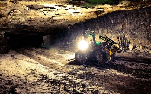
LION: Lidar-Inertial Observability-Aware Navigator                                                7

Fig. 10: Comparison of the translation error with and without the observability module in an office-
like environment. On the left, the observability module is not used, which creates a lidar slip in
the first part of the corridor, producing an error of ≈ 9 m. On the right, the observability module
is used, and the switching-logic HERO switches to WIO instead of LION for the section of the
corridor without lidar features. The total error is ≈ 1 m (“Before loop closure”). Improved state
estimation (reduced drift in the output of HeRO) benefits the global mapping solution [35], which
can now correctly detect a loop closure (Fig. 10 “After loop closure”), further reducing the drift.

along the direction of the corridor. We also use the dataset Arch-Coal-Mine,
recorded in the Arch Coal Mine (see Fig. 8), which consists of a straight tunnel fol-
lowed by an intersection. The plots of the condition number and the eigenvectors
scaled with the eigenvalues for the JPL-Corridor dataset are shown in Fig. 8.
At the beginning and the end of the corridor, there are enough features in all the
directions, and the condition number is κ(Att ) ≈ 2. However, in the middle of the
corridor, the condition number reaches values κ(Att ) > 13, which happens when
the eigenvalue associated with the eigenvector along the direction of the tunnel be-
comes really small. This big condition number makes it hard to determine if the
robot is moving based on changes in the geometry of the incoming point clouds.
A similar situation happens in the Arch-Coal-Mine dataset (see Fig. 9). Before
and after the intersection, κ(Att ) > 10 indicates the low observability along the
main shaft. The observability is improved when the robot reaches the intersection,
in which the condition number is κ(Att ) ≈ 4. Note also the symmetry in the inter-
section of the two scaled eigenvectors that point to the two different corridors.
   Using this condition number as the observability metric, HeRO can decide to
switch to other odometry sources different from LION (like WIO) when there are
not enough lidar features. This behavior is shown in Fig. 10 for a real experiment
carried out in an office-like environment where a section of the first corridor does
not have enough lidar features. If the observability module is not used, this lack of
features in the corridor creates a lidar slip, where the movement of the robot is not
well observed by LION. This produces a total error of ≈ 9 m when the robot goes
back to the original position. However, when the observability module is used, the
lack of observability in the direction of the corridor is detected, and WIO is used for
that section of the corridor, instead of LION. This produces a total error of ≈ 1 m,
8                                                   A. Tagliabue, J. Tordesillas, X. Cai et al.

which is small enough to trigger a successful loop-closure in the employed global
mapping solution [35].
4 EXPERIMENTAL INSIGHTS AND CONCLUSIONS

This work presented LION, a Lidar-Inertial Observability-Aware algorithm for Nav-
igation of robots in vision-denied environments. LION has been extensively tested
in different subterranean environments, including the Tunnel Competition of the
DARPA Subterrranean Challenge in August 2019. In the following we review the
insights and reasons behind some of the choices made, as well as the main outstand-
ing technical challenges.
    • Local state estimator: The main goal of LION is to provide a high-rate, con-
      tinuous and smooth output to the downstream algorithms. As such, LION does
      not build any map and does not perform any loop closures, and thus its iner-
      tial reference frame will slowly drift over time. The slow drifts in the output of
      LION are compensated by the mapping strategy LAMP [35], which is running
      within the localization framework.
    • Loosely-coupled architecture: In contrast to other state-of-the-art works [16–
      18], the lidar front-end and back-end of LION are loosely-coupled (i.e., we
      do not explicitly add features point or scans in the state of the estimator). The
      main reason behind this was the desire of sharing the computational resources
      required by the lidar front-end with the mapping solution [35]. In addition, such
      architecture was dictated by the need of modularity in choosing front-end/back-
      end algorithms, and distributing the risk between several estimation engines to
      remove the one-point failure in case of a single estimation engine.
    • Not feature-based: In LION, and contrary to [18], no features are extracted to
      match two point clouds because of two reasons. On one hand, feature extrac-
      tion is usually computationally expensive, which would lead to a reduction of
      the performance of other modules of LION due to the limited computational
      resources onboard. Moreover, LION is meant for exploration of completely un-
      known environments, where there could be human-made structures (full of cor-
      ners, planes and lines) or completely unstructured terrains. The use of feature
      extraction for such uncertain environments poses a prior on the environment the
      robot is going to navigate through, leading therefore to its own risks or failures.
    • Automatic extrinsic calibration: lidar to IMU calibration is critical, especially
      in the relative orientation of the two sensors, since small errors can quickly in-
      tegrate and cause a large drift. Offline calibration methods require a calibration
      target [36] and/or specific motion sequences [37], and can be impractical in a
      field setup where the sensor can be re-positioned at the last minute. This is the
      reason why we choose to estimate the extrinsics directly with LION.
    • Supervisory Algorithm: LION has been designed to be one of the many odom-
      etry sources used by HeRO [4], a switching logic that multiplexes different
      odometry sources such as wheel encoders, visual-inertial or thermal-inertial
      odometry. The selection of one of these odometry sources is done according
      to the reliability of their output as state estimate. The confidence metrics for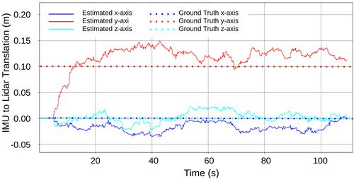
LION: Lidar-Inertial Observability-Aware Navigator                                              9

     LION include its output rate, the detection of the potential failures in its inputs
     (lidar and IMU), and the observability score detailed in Section 2.

ACKNOWLEDGMENTS

The authors would like to thank Kasra Khosoussi (ACL-MIT), Benjamin Morrell
(JPL) and Kamak Ebadi (JPL) for helpful insights and discussions. Part of this re-
search was carried out at the Jet Propulsion Laboratory, California Institute of Tech-
nology, under a contract with the National Aeronautics and Space Administration.

References

 1. A. Agha, K. L. Mitchell, and P. Boston, “Robotic exploration of planetary subsurface voids in
    search for life,” in AGU Fall Meeting Abstracts, vol. 2019, 2019, pp. P41C–3463.
 2. “Team costar,” https://costar.jpl.nasa.gov/, (Accessed on 06/29/2020).
 3. “Darpa subterranean challenge,” https://subtchallenge.com/, (Accessed on 06/29/2020).
 4. A. Santamaria-Navarro, R. Thakker, D. D. Fan, B. Morrell, and A.-a. Agha-mohammadi,
    “Towards resilient autonomous navigation of drones,” in The International Symposium on
    Robotics Research, 2019.
 5. M. Bloesch, S. Omari, M. Hutter, and R. Siegwart, “Robust visual inertial odometry using a
    direct EKF-based approach,” in IROS 2015 IEEE/RSJ international conference on intelligent
    robots and systems (IROS). IEEE, 2015, pp. 298–304.
 6. T. Qin, P. Li, and S. Shen, “Vins-mono: A robust and versatile monocular visual-inertial state
    estimator,” IEEE Transactions on Robotics, vol. 34, no. 4, pp. 1004–1020, 2018.
 7. R. Mur-Artal, J. M. M. Montiel, and J. D. Tardos, “ORB-SLAM: a versatile and accurate
    monocular SLAM system,” IEEE transactions on robotics, vol. 31, no. 5, pp. 1147–1163,
    2015.
 8. C. Forster, Z. Zhang, M. Gassner, M. Werlberger, and D. Scaramuzza, “svo: Semidirect visual
    odometry for monocular and multicamera systems,” IEEE Transactions on Robotics, vol. 33,
    no. 2, pp. 249–265, 2016.
 9. T. Neumann, A. Ferrein, S. Kallweit, and I. Scholl, “Towards a mobile mapping robot for
    underground mines,” in Proceedings of the 2014 PRASA, RobMech and AfLaT International
    Joint Symposium, Cape Town, South Africa, 2014, pp. 27–28.
10. C. Papachristos, S. Khattak, F. Mascarich, and K. Alexis, “Autonomous navigation and map-
    ping in underground mines using aerial robots,” in 2019 IEEE Aerospace Conference. IEEE,
    2019, pp. 1–8.
11. P. J. Besl and N. D. McKay, “Method for registration of 3D shapes,” in Sensor fusion IV: con-
    trol paradigms and data structures, vol. 1611. International Society for Optics and Photonics,
    1992, pp. 586–606.
12. Y. Chen and G. Medioni, “Object modelling by registration of multiple range images,” Image
    and vision computing, vol. 10, no. 3, pp. 145–155, 1992.
13. Z. Zhang, “Iterative point matching for registration of free-form curves and surfaces,” Inter-
    national journal of computer vision, vol. 13, no. 2, pp. 119–152, 1994.
14. M. Magnusson, A. Lilienthal, and T. Duckett, “Scan registration for autonomous mining ve-
    hicles using 3d-ndt,” Journal of Field Robotics, vol. 24, no. 10, pp. 803–827, 2007.
15. F. Pomerleau, F. Colas, R. Siegwart, and S. Magnenat, “Comparing icp variants on real-world
    data sets,” Autonomous Robots, vol. 34, no. 3, pp. 133–148, 2013.
16. T. Shan and B. Englot, “LeGO-LOAM: Lightweight and ground-optimized lidar odometry and
    mapping on variable terrain,” in IROS 2018 International Conference on Intelligent Robots
    and Systems (IROS). IEEE, 2018, pp. 4758–4765.
10 A. Tagliabue, J. Tordesillas, X. Cai et al.
17. H. Ye, Y. Chen, and M. Liu, “Tightly coupled 3D lidar inertial odometry and mapping,” arXiv
preprint arXiv:1904.06993, 2019.
18. J. Zhang and S. Singh, “LOAM: Lidar odometry and mapping in real-time.” in Robotics:
Science and Systems, vol. 2, 2014, p. 9.
19. C. Qin, H. Ye, C. E. Pranata, J. Han, S. Zhang, and M. Liu, “LINS: A lidar-inertial state
estimator for robust and efficient navigation,” arXiv preprint arXiv:1907.02233, 2019.
20. G. Hemann, S. Singh, and M. Kaess, “Long-range GPS-denied aerial inertial navigation with
lidar localization,” in IROS 2016 International Conference on Intelligent Robots and Systems
(IROS). IEEE, 2016, pp. 1659–1666.
21. J. Lin and F. Zhang, “Loam_livox: A fast, robust, high-precision lidar odometry and mapping
package for lidars of small fov,” arXiv preprint arXiv:1909.06700, 2019.
22. C. Forster, L. Carlone, F. Dellaert, and D. Scaramuzza, “IMU preintegration on manifold for
efficient visual-inertial maximum-a-posteriori estimation.” Georgia Institute of Technology,
2015.
23. N. Gelfand, L. Ikemoto, S. Rusinkiewicz, and M. Levoy, “Geometrically stable sampling for
the ICP algorithm,” in Fourth International Conference on 3-D Digital Imaging and Modeling,
2003. 3DIM 2003. Proceedings. IEEE, 2003, pp. 260–267.
24. J. Zhang, M. Kaess, and S. Singh, “On degeneracy of optimization-based state estimation
problems,” in ICRA 2016 on Robotics and Automation (ICRA). IEEE, 2016, pp. 809–816.
25. A. Censi, “An accurate closed-form estimate of ICP’s covariance,” in Proceedings 2007 IEEE
international conference on robotics and automation. IEEE, 2007, pp. 3167–3172.
26. J. Zhang and S. Singh, “Enabling aggressive motion estimation at low-drift and accurate map-
ping in real-time,” in ICRA 2017 Conference on Robotics and Automation (ICRA). IEEE,
2017, pp. 5051–5058.
27. A. Hinduja, B.-J. Ho, and M. Kaess, “Degeneracy-aware factors with applications to under-
water slam.” in IROS, 2019, pp. 1293–1299.
28. M. Kaess, H. Johannsson, R. Roberts, V. Ila, J. J. Leonard, and F. Dellaert, “iSAM2: Incre-
mental smoothing and mapping using the bayes tree,” The International Journal of Robotics
Research, vol. 31, no. 2, pp. 216–235, 2012.
29. F. Dellaert, “Factor graphs and gtsam: A hands-on introduction,” Georgia Institute of Tech-
nology, Tech. Rep., 2012.
30. R. Thakker, N. Alatur, D. D. Fan, J. Tordesillas, M. Paton, K. Otsu, and A.-a. Agha-
mohammadi, “Autonomous traverse of off-road extreme terrains in dark and dust: An ex-
perimental perspective on physical mobile robots.” in ISER, 2020.
31. A. Segal, D. Haehnel, and S. Thrun, “Generalized-icp.” in Robotics: science and systems,
vol. 2, no. 4. Seattle, WA, 2009, p. 435.
32. C. Forster, L. Carlone, F. Dellaert, and D. Scaramuzza, “On-manifold preintegration theory for
fast and accurate visual-inertial navigation,” IEEE Transactions on Robotics, pp. 1–18, 2015.
33. M. Palieri, B. Morrell, A. Thakur, K. Ebadi, J. Nash, L. Carlone, C. Guaragnella, and A. Agha-
mohammadi, “Locus-a multi-sensor lidar-centric solution for high-precision odometry and 3d
mapping in real-time,” Under Review, 2020.
34. S. Bonnabel, M. Barczyk, and F. Goulette, “On the covariance of ICP-based scan-matching
techniques,” in 2016 American Control Conference (ACC). IEEE, 2016, pp. 5498–5503.
35. K. Ebadi, Y. Chang, M. Palieri, A. Stephens, A. Hatteland, E. Heiden, A. Thakur, B. Morrell,
L. Carlone, and A. Aghamohammadi, “LAMP: large-scale autonomous mapping and posi-
tioning for exploration of perceptually-degraded subterranean environments,” in ICRA 2020
International Conference on Robotics and Automation (ICRA), 2020.
36. C. Le Gentil, T. Vidal-Calleja, and S. Huang, “3d lidar-imu calibration based on upsam-
pled preintegrated measurements for motion distortion correction,” in ICRA 2018 Automation
(ICRA). IEEE, 2018, pp. 2149–2155.
37. B. Della Corte, H. Andreasson, T. Stoyanov, and G. Grisetti, “Unified motion-based calibra-
tion of mobile multi-sensor platforms with time delay estimation,” IEEE Robotics and Au-
tomation Letters, vol. 4, no. 2, pp. 902–909, 2019.You can also read