Sub-6 GHz mMIMO Base Stations Meet 5G's Size and Weight Challenges - Macom
←
→
Page content transcription
If your browser does not render page correctly, please read the page content below
Cover   Feature
                                                                                             Invited Paper

Sub-6 GHz mMIMO Base
Stations Meet 5G’s Size and
Weight Challenges
Walter Honcharenko
MACOM, Lowell, Mass.

Base station deployment and site acquisition constraints require smaller, lighter 5G massive
MIMO (mMIMO) radios and antennas. Improved signal processing, high efficiency devices and
integration from discrete lineups to front-end modules (FEM) make it possible.

T
          he RF and microwave in-        ever-increasing demand for data—            tem where interference is managed.
          dustry has made consid-        requires a fundamental change in            Here is where mMIMO systems
          erable progress toward         cellular communication RF system            come into the picture. mMIMO,
          enabling commercial sub-       architecture and design. With so            with many more transceivers and
6 GHz 5G wireless infrastructure,        many users, devices, automobiles,           antenna elements than are used
with mmWave fixed wireless trials        smart meters, low-power wide-area           in 4G systems, uses beamforming
progressing in parallel. The early       devices and other machine-to-ma-            signal processing to direct RF en-
excitement surrounding 5G has            chine communication, the capacity           ergy to users and reduce interfer-
given way to a defined set of indus-     of 4G cellular systems employing            ence by dynamically steering an-
try standards, and component and         fixed sector antenna systems will fall      tenna beams away from interfering
system manufacturers have vari-          short. At the highest level of com-         sources, in both azimuth and eleva-
ously aligned on practical, scalable     munication theory, it is well known         tion. By steering RF energy to users
5G base station architectures that       that maximizing throughput over a           and away from interference, SINR,
deliver the promise of faster data       wireless channel requires maximiz-          throughput and overall system ca-
throughput and expansive capacity        ing signal-to-noise ratios (SNR) or         pacity improve.
to serve subscriber, IoT and other       signal-to-interference+noise ratios
applications.                            (SINR). High density cellular net-          mMIMO CHALLENGES
   The evolution from 4G to 5G—          works are typically interference lim-          With 5G antenna array and mMI-
and the anticipated 100× capac-          ited, not noise limited, forcing the        MO technology coming to fruition,
ity improvement required by our          RF architecture to evolve into a sys-       wireless network operators will face
                       Reprinted with permission of MICROWAVE JOURNAL® from the February 2019 issue.
                                               ©2019 Horizon House Publications, Inc.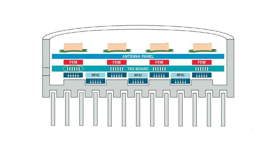
CoverFeature
deployment challenges as they make These challenges must be met rable indoor coverage. Diffraction
the transition from 4G LTE to 5G with smaller, denser sub-6 GHz 5G losses, aperture efficiencies and
base stations, an incremental evolu- base station designs. In parallel, path loss all suffer as a function of
tion that will see both technologies base station weight and volume re- frequency (i.e., 6 to 12 dB/octave),
comingled for what is likely to be an main critical considerations for sys- while penetration losses increase
extended period. Occupying similar tem designers, given the nontrivial dramatically at higher frequencies
physical footprints, 4G LTE and 5G labor and equipment costs imposed due to the skin depth and conduc-
base stations will, wherever possible, on wireless operators for installa- tivity of coated glass, conductive
populate existing co-located cell tion and subsequent maintenance. (moist) masonry, brick faces and
towers and rooftop installations, con- Where operating costs were cal- other materials.
figured as they are today to minimize culated based on just the aperture Health and safety requirements
interference and coverage gaps. size of the antenna, tower opera- dictate that EIRP emission limits (1
As 5G base stations proliferate tors have largely moved to a pricing mW/cm2) and exclusion zones re-
across existing sites, available instal- model where charges are calculated main within acceptable levels in
lation space will shrink dramatically, using base station weight, aperture the transition from 4G LTE to 5G,
space that is already at a premium area and volume. Initial installation so raising EIRP levels will naturally
from continued 4G LTE base station costs are also determined by the introduce some placement chal-
deployments in some regions. In- location, weight and type of instal- lenges. These will be compounded
deed, many cell towers have already lation: tower or rooftop, one or two with the implementation of mMIMO
been pushed to the brink of their people, crane, etc. The initial 4G beamforming techniques if theoreti-
hosting capacities, evidenced by systems were split into a radio head cal maximum power is used. Where
the increasingly and chaotically-clut- and an antenna, where the radio was conventional antennas point hori-
tered towers dotting today’s metro often on the ground and the passive zontally, beam steered antenna ar-
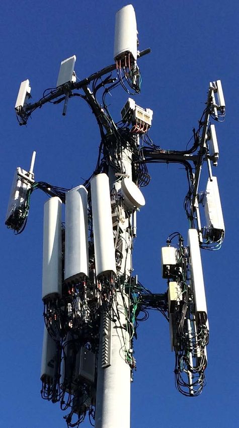
environments. Figure 1 shows a antenna mounted on the tower. In rays will radiate in many directions,
typical tower installation with two other installations, both radio and even down into pedestrian walk-
tiers of antennas, radios, RF cables antenna were located on the tower, ways. This health and safety con-
and power feed lines, which repre- with commensurate costs. 5G mMI- cern will introduce additional con-
sent approximately 250 kg weight MO antennas, by definition, will straints for acquiring urban 5G base
on each sector. Wind loading, ice position the active electronics on station sites, intensifying the pres-
loading and moment arms are key the tower, immediately behind the sure to design smaller, lower power
factors as base stations multiply on antenna, in a single integrated unit. base stations that can be flexibly
a tower, with concern for base sta- Of course, base station size and deployed while preserving safety.
tion resilience and service continuity weight have always and will always
in poor weather conditions. be central concerns for RF com- REDUCING SIZE AND WEIGHT
ponent providers, base station de- When it comes to optimizing sub-
signers and operators. A looming 6 GHz base station size and weight,
shortage of tower and rooftop real several design considerations must
estate will only exacerbate these be considered, from the component
problems. On the path to realiz- to the system, with power consump-
ing commercial-scale mmWave 5G tion, efficiency and thermal dissipa-
connectivity, site acquisition will be- tion the most important.
come infinitely more difficult, given Antenna aperture size is wholly
the 100 m spacing between base dependent on the number of on-
stations that frequency and phys- board antenna elements, which
ics require for uniform coverage. depends on the desired network
mmWave base station equipment capacity and expected interference.
installed on lamp posts, street signs, Whether the array has 64, 128 or
bus stop shelters and other struc- 192 elements, the physical dimen-
tures will need to be far lighter and sion is determined by the physics
less obtrusive than anything that has of the array, scanning angle require-
come before. ments, grating lobe performance
Site acquisition challenges will be and beam widths. The volume and
compounded by concerns over the depth of the base station, deter-
effective isotropic radiated power mined by the underlying electronics
(EIRP). While 4G LTE and sub-6 GHz and heat sinking, can absolutely be
5G base stations may exhibit com- optimized; here, we see plenty of
parable EIRP levels when account- room for improvement.
ing for beamforming gain, increas- A key system size consideration
ingly higher frequencies will require frequently overlooked with 5G mMI-
higher RF power to compensate MO is the dramatic increase in sig-
Fig. 1 Typical cell tower installation, for building penetration losses and nal processing hardware required,
with two tiers of radios and antennas. boost the EIRP to achieve compa- compared to typical LTE systems.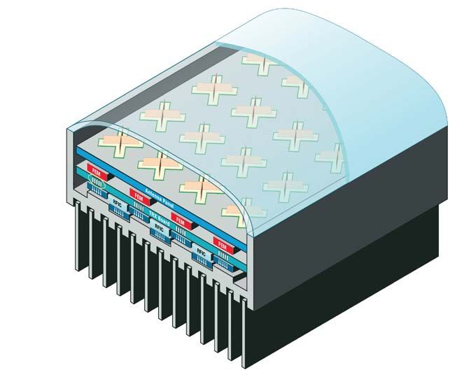
CoverFeature
The mMIMO system may have 192 antenna elements
connected to 64 transmit/receive (TRx) FEMs with 16
transceiver RFICs and four digital front-ends (DFE), a
16× increase in digital signal processing compared to
the four transceivers in a typical LTE 4T MIMO system
(see Figure 2). Add a 5× increase in bandwidth when
moving from 20 to 100 MHz, for example, and the sig-
nal processing multiplier is staggering. The stackup in
4T Antenna Figure 3 illustrates the functions in a typical mMIMO in-
mMIMO Antenna
tegrated antenna and radio. The top panel contains the
Integrated Assembly
antenna elements, and the layers below the antenna
contain the RF and digital circuitry. While the TRx FEM,
RFIC and DFE layers are shown as separate boards, in
practice the three functions will be combined into one
or two densely packed boards to minimize interconnec-
tions.
Perhaps even more jarring than the additional hard-
ware in a mMIMO system is the attendant impact on
A/D
A/D
A/D
A/D
D/A
D/A
D/A
D/A
power consumption and heat dissipation. Previously,
DFE
Signal Conditioning
CFR/DPD/Tx/Rx
FEM
RFIC
4T LTE RRH mMIMO Radio
CPRI CPRI
Baseband Baseband
(a) (b)
Baseband
Fig. 2 Architecture of a conventional 4T LTE remote radio
head (a) vs. a mMIMO radio containing 192 antenna elements
and 64 TRx FEMs (b). Fig. 3 Notional mMIMO radio stackup.
FEM 4 Channel RFIC/Transceiver 16 Channel DFE Function
Pulse
D/A P Q DPD CFR Shaping IFFT
Q P Pulse
A/D Shaping FFT
FEM
Pulse
D/A P Q DPD CFR Shaping IFFT
Pulse
A/D Q P Shaping FFT
FEM 4 Channel RFIC/Transceiver Beamforming/
Channel
Pulse
D/A P Q DPD CFR Shaping IFFT Estimation/ to Baseband
Coefficient
Q P Pulse Management
A/D Shaping FFT
FEM
Pulse
D/A P Q DPD CFR Shaping IFFT
Q P Pulse
A/D Shaping FFT
64 Total FEMs 16 x of 4 4 x of 16
in 64 TRx Architecture Channel RFIC Channel DFE
Fig. 4 Typical mMIMO radio functional block diagram.CoverFeature
power amplifier (PA) power con- functional block diagram is shown in mance and superior power density
sumption was the most important Figure 4. This architecture is typical and efficiency compared to LDMOS
factor when designing base sta- of all mMIMO designs, with some devices, meeting the exacting ther-
tion heat sinks and power supplies. differences in the partitioning of mal specifications while preserving
Now, the power consumption of logic (e.g., 8- or 16-channel DFEs) valuable PCB space for the tightly-
the signal processing electronics is or discrete component instead of clustered mMIMO antenna arrays.
approaching, and in some cases, integrated FEMs. This example Space-saving multifunction MMICs
eclipsing that of the onboard PAs. shows, from left to right, 64 RF and and multi-chip modules (MCM) are
The significant increase in signal transceiver paths divided among supplanting discrete ICs and single-
processing hardware can be offset 16 transceiver RFICs driving four function devices, enabling inte-
to an extent by optimizing the sig- DFEs. The DFEs process the digi- grated RFICs for 5G base stations.
nal and waveform conditioning al- tal data from the 64 channels and FEMs are benefiting from a similarly
gorithms applied to the transmitted are connected to the beamforming streamlined design approach us-
signals. Legacy signal conditioning processor and baseband interface ing integrated assemblies incorpo-
algorithms such as crest factor re- processor. The emergence of RF rating PAs, T/R switches, matching
duction and digital predistortion SOCs with direct sampling analog- circuits, low noise amplifiers, digital
(DPD) were primarily developed for to-digital converters (ADC) and step attenuators, controllers and
macro base stations with very high- digital-to-analog converters (DAC) DPD couplers packaged in compact
power PAs, a more complicated and capable of ~60 GSPS help to shrink packages (see Figure 5). With drain
taxing processing workload than is the size and weight of 5G antennas efficiencies approaching 60 percent
required for the smaller, lower pow- by reducing the steps required for and optimized integration of the
er PAs populating mMIMO anten- analog up- and down-conversion Tx and Rx components, as well as
nas. These algorithms easily con- in conventional transceiver archi- DPD feedback paths, using FEMs in
sumed 75 percent of the available tectures. This reduces the overall mMIMO radios and TRx boards has
signal processing resources in the component count and cost by elimi- many benefits:
DFE processors, whether custom nating mixers, converters and local • Reuse portions of the transceiver
ASIC/SOCs or FPGAs. By stream- oscillators. board layout.
lining these algorithms for 5G • Optimize device-to-heat sink
mMIMO architectures and redistrib- FEM BENEFITS thermal management.
uting the functionality across several The emergence of GaN on Si • Optimize power levels, feedback
logic blocks, a minimal set of opti- PAs provides wideband perfor- loops, VSWR and control circuitry.
mized algorithms will improve sig- • Manage isolation and noise with-
nal processing efficiency, reducing Radome in the FEM.
overall power consumption. AI or Mg • Enable dynamic power saving
To illustrate the 16× multiplier Housing modes.
of the digital signal processing and • Improve final yields compared to
transceivers in a mMIMO system, a discrete designs, since the inte-
grated FEM is fully tested.
Using the FEM design approach,
To Filter redesigning a mMIMO radio for a dif-
and TX In ferent number of antenna elements,
Antenna PA Control frequency band or power level is sim-
Thermal
RX Out
Vias plified, as FEMs are “plug and play”
50 Ω Thermal modules, with standardized interfac-
Pads
Bonded
es, control logic and RF levels part of
Fins the design methodology.
Fig. 5 Simplified FEM block diagram. Fig. 6 Integrated mMIMO radio.
THERMAL DESIGN
In all mMIMO designs, where the
Radome antenna and electronics are con-
AI or Mg
tained in one enclosure (see Figure
Housing 6), the majority of the product engi-
neering focus is managing thermal
Thermal Dissipation
Thermal
Vias performance. The engineering ef-
Thermal forts for signal processing, RF de-
Pads
sign, digital design, board layout,
power design are indeed complex,
but ultimately the mechanical/ther-
Bonded mal/design and product environ-
Fins
mental requirements will determine
the volume and weight. Conven-
Fig. 7 Integrated mMIMO radio cross section showing layers and heat conduction paths. tional 4G radio heads are built withCoverFeature the radio inside the heat sink, fins the heat from the RFICs conducts options for the foreseeable future. surrounding the entire package. out through the lid. This allows heat By alleviating the signal processing With a mMIMO design, the antenna to be dissipated in multiple direc- and conversion workload and ex- and its radome are very poor con- tions, rather than unidirectionally ploiting higher levels of integration, ductors of heat, limiting thermal dis- from the FEMs and RFICs. Heat can from discrete components to FEMs, sipation to the rear of the mMIMO be removed through the top lid and significant reductions in base station radio. the bottom of the package through size and weight can be achieved. By leveraging advanced packag- the ground vias and baseplate, dis- The expected roadmap for FEMs, ing techniques for the MMICs and tributing heat more efficiently and SOCs and full single module solu- MCMs within the FEM, additional enabling a cooler device in a smaller tions, from optical in to RF out, is a cooling and space-saving benefits footprint. Alternatively, the FEM can natural progression of technology. can be achieved. Figure 7 illustrates channel heat through both the ther- Integration of the optical interfaces, a simplified mMIMO design, not mal vias and the lid, to dissipate as with direct sampling RF Tx and Rx including the power supplies and much heat as possible. and the required signal condition- fiber interfaces. The case housing ing, will define a true SOC. These has extruded fins bonded into the SUMMARY evolving capabilities will enable 5G housing to save casting weight and The impending proliferation of 5G mMIMO base stations to become increase thermal efficiency. The TRx base stations operating sub-6 GHz, ubiquitous, fitting comfortably in board integrates the FEMs and RF- later at mmWave, will undoubtedly the contours of our metro and sub- ICs, with the FEMs conducting heat strain tower and rooftop deploy- urban landscapes.n down through thermal vias, while ment flexibility and site acquisition
You can also read