Characteristics of parametric spin waves in rectangular magnonic blocks - IOPscience
←
→
Page content transcription
If your browser does not render page correctly, please read the page content below
Journal of Physics D: Applied Physics

PAPER • OPEN ACCESS

Characteristics of parametric spin waves in rectangular magnonic blocks
To cite this article: S Hwang et al 2021 J. Phys. D: Appl. Phys. 54 365001

View the article online for updates and enhancements.

                               This content was downloaded from IP address 46.4.80.155 on 03/08/2021 at 09:37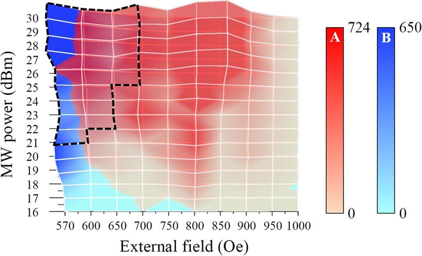
Journal of Physics D: Applied Physics
J. Phys. D: Appl. Phys. 54 (2021) 365001 (8pp) https://doi.org/10.1088/1361-6463/ac0ad2
Characteristics of parametric spin
waves in rectangular magnonic blocks
S Hwang1,2, Seungha Yoon2, B R Kim1, S H Han3 and B K Cho1,∗
1
School of Materials Science and Engineering, Gwangju Institute of Science and Technology (GIST),
Gwangju 61005, Republic of Korea
2
Smart Energy & Nano Photonics Group, Korea Institute of Industrial Technology, Gwangju 61012,
Republic of Korea
3
Division of Navigation Science, Mokpo National Maritime University, Mokpo 58628, Republic of Korea
E-mail: chobk@gist.ac.kr
Received 20 January 2021, revised 17 May 2021
Accepted for publication 11 June 2021
Published 24 June 2021
Abstract
The characteristics of parametric spin-wave pumping are investigated in three rectangular
permalloy blocks with in-plane aspect ratios of 12, 6, and 4. Micro-Brillouin light scattering
(BLS) spectroscopy is utilized to detect the intrinsic properties of excited spin waves under
various excitation conditions of an external magnetic field and microwave power. Based on the
theoretical dispersion relation and BLS intensity and its spatial profile, the parametric spin wave
with a frequency of fsw = 5.6 GHz is found to be excited in fundamental mode in a block of
largest aspect ratio while the other block have higher-order or edge-localized modes along the
width direction. The data shows that the nature of spin waves is quite sensitive on the conditions
of sample geometry, applied field and microwave power. Thus, with the appropriate
combination of the three parameters, it would be possible to control the nature of spin wave in
each block simultaneously, which increase the blocks’ potential in magnonic applications, such
as spin-logic and interferometer.
Supplementary material for this article is available online
Keywords: parallel parametric pumping, spin wave, magnonics, rectangular block,
threshold characteristics
(Some figures may appear in colour only in the online journal)
1. Introduction is spin-wave excitation for efficient signal transmission. For
data processing, spin waves must be transmitted to the manipu-
Over the last few decades, the field of so-called magnon- lation area, while overcoming the signal loss due to spin-wave
ics [1–4], where spin waves are utilized as information car- damping. To achieve low-loss transmission, the study of excit-
riers, has been studied intensively. One attractive application ation techniques suitable for magnetic systems is essential.
of magnonics is its use in low-loss and ultra-fast non-volatile The coupling of magnetization m with a microwave field
logic devices. To improve the feasibility of magnonic logic H mw , induced by a microwave current, is the most com-
systems, there are several issues to be addressed, one of which mon spin-wave excitation method. There are two represent-
ative excitation mechanisms, depending on the angle between
∗
H mw and the external field H ex . In linear excitation, i.e. force
Author to whom any correspondence should be addressed.
excitation, the orientation of H mw is perpendicular to H ex ,
and the spin-wave frequency is identical to that of H mw [5].
Original content from this work may be used under the terms
In force excitation, an antenna that guides the microwave
of the Creative Commons Attribution 4.0 licence. Any fur-
ther distribution of this work must maintain attribution to the author(s) and the current should be situated across a magnetic element. Both
title of the work, journal citation and DOI. the antenna width and the microwave-field uniformity limit
1361-6463/21/365001+8$33.00 1 © 2021 The Author(s). Published by IOP Publishing Ltd Printed in the UK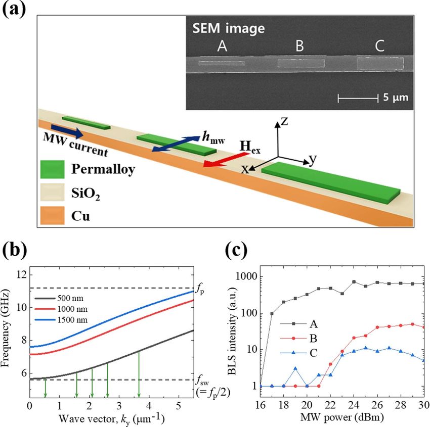
J. Phys. D: Appl. Phys. 54 (2021) 365001                                                                                    S Hwang et al

the characteristics of the excited spin wave [6, 7]. With this          Analysis of the data in terms of the calculated dispersion rela-
structural restriction, only a spatially symmetric spin wave            tion reveals that the pumping efficiency and nature of spin
with a long wavelength, in principle, can be excited. To achieve        waves are sensitive to size variation in magnetic blocks.
short wavelength (≈50 nm), additional hetero-structure, rather
than a simple waveguide, should be introduced in the forced
excitation [8]. In contrast, parallel parametric pumping [9],           2. Experimental details
where H mw is applied parallel to H ex , induces nonlinear excit-
                                                                        Spectroscopic measurement is carried out using a µ-BLS
ation, in which the microwave photon with frequency f p splits
                                                                        system, interfaced with a programmable computer [29]. The
into two spin waves with opposite wave vectors, both with fre-
                                                                        µ-BLS system possesses a microscope objective with a high
quency f p /2.
                                                                        magnification (100×) and large numerical aperture (0.75) to
    In a parametric process, pumped spin wave has a much lar-
                                                                        obtain a beam spot size of approximately 250 nm in diameter,
ger amplitude than the spin wave created by force excitation,
                                                                        which significantly enhances the lateral resolution limit. The
and a wide range of wave vectors from dipolar- to exchange-
                                                                        incident beam, generated by a 532 nm-wavelength, diode-
dominant can be excited when the microwave power P exceeds
                                                                        pumped solid laser, is focused on a specific position in the
a certain threshold value Pth [10]. The threshold is determined
                                                                        magnonic block through the objective lens. The sample is loc-
by the damping parameter of the magnetic material and the
                                                                        ated on an x–y–z piezoelectric stage for spatial scanning at
ellipticity of magnetic precession-i.e. the ratio of the in-plane
                                                                        the nanometer scale to plot an intensity map of the spin-wave
magnetization components. That is, low damping and high
                                                                        mode. Light scattered from spin waves in the permalloy (Py)
ellipticity enhance the parametric pumping efficiency [11].
                                                                        blocks passes through a (3 + 3) pass tandem Fabry–Perot
Another pumping condition is that the half of f p should be lar-
                                                                        interferometer to obtain a frequency-domain spectrum. The
ger than the minimum frequency f min of the spin-wave band in
                                                                        laser intensity in our experiment is reduced to less than 1 mW
the corresponding magnetic structure [12]. On the other hand,
                                                                        to minimize possible thermal effects.
it should be mentioned that there can be also the exceptional
                                                                            Figure 1(a) shows the schematic geometry of the system
case, such as threshold process involved off-resonant driven
                                                                        setup. Rectangular Py blocks of 30 nm thickness, 6 µm length
spin wave mode with wave vectors near k = 0 in a nano-
                                                                        (l), and various widths (w) are fabricated using e-beam litho-
structure [13]. In this case, the spin waves with the slightly
                                                                        graphy and magnetron sputtering on a Cu antenna of 200 nm
lower frequency than f min can be excited. The conversion of
                                                                        thickness. The clear SEM image is shown in the inset. Each
input microwaves of frequency f p in a parametric process can
                                                                        block is named, depending on its width: A, B, and C: 500,
be controlled by adjusting the dispersion relation of the excited
                                                                        1000, and 1500 nm width, respectively. A 30 nm thick SiO2
wave vectors, which depends on the magnitude of H ex . Thus,
                                                                        layer is deposited between the blocks and antenna for insu-
microwave power and frequency, and the magnitude of the
                                                                        lation. The external field is applied along the width direc-
external field are the key parameters in modulating the para-
                                                                        tion. The microwave current for parametric pumping has a
metric process to produce various wave modes.
                                                                        11.2 GHz pulse over a duration of 500 ns, with a repetition
    Another issue is the manipulation of spin waves for logical
                                                                        time of 1 µs to prevent thermal degradation due to Joule heat-
operation. For example, various types of magnonic crystals
                                                                        ing. The dynamic field, induced by the microwave current,
(MCs), as components in logic devices, have been studied
                                                                        should be parallel to the external field direction. In addition,
[14–17]. MCs, comprising periodically patterned magnetic
                                                                        the micromagnetic simulation, OOMMF [30], was performed
media, allow the construction of artificially tailored band
                                                                        to ensure the existence of the magnetization component par-
structures and, consequently, the modulated magnetic proper-
                                                                        allel to the microwave field. The structural geometry for the
ties required by spin-wave waveguides [18, 19], filters [20, 21],
                                                                        simulation is same as the thickness and in-plane aspect ratio
and multiplexers [22, 23]. In particular, a width-modulated
                                                                        of block A. It shows that the magnetization, parallel to the
structure [24–26] is representative of MC structure, and util-
                                                                        excitation field, is aligned even with the lowest applied field,
izes wave-reflection properties in conjunction with the differ-
                                                                        570 Oe, in our experiment (see the supplementary information,
ence of the dispersion relation due to variation in the width
                                                                        figure S-1 (available online at stacks.iop.org/JPD/54/365001/
w of a unit block. Thus, it is necessary to better under-
                                                                        mmedia)). Accordingly, our experimental geometry satisfies
stand the dispersion relations of MC blocks for the compre-
                                                                        the condition for parallel parametric pumping. It should be
hensive interpretation of signal processing. The size effect,
                                                                        mentioned that we expect energy loss in this system because
as well as difference of dispersion relation, also affects the
                                                                        the Cu micro-stripe antenna serves as a kind of waveguide. So,
threshold property of parametric excitation as the concentra-
                                                                        it would be possible to excite the spin waves with less power
tion of pumping energy is more efficient in a smaller volume
                                                                        than that in this study once elegant wave guides are adopted in
[27, 28].
                                                                        system. The measurements for the individual block show the
    In this paper, parametric pumping characteristics are invest-
                                                                        same features, presented in this manuscript.
igated in three rectangular blocks with identical length and
thickness, but various widths, i.e. the in-plane aspect ratios
(length/width) of 12, 6, and 4. The pumping threshold and               3. Results and discussion
spin wave properties are studied using a micro-Brillouin light
scattering (µ-BLS) spectrum and its spatial profiles, with              It is well known that parametric excitation is closely related
a combination of three control parameters: w, H ex , and P.             to the dispersion relation of the corresponding spin-wave

                                                                    2
J. Phys. D: Appl. Phys. 54 (2021) 365001                                                                                               S Hwang et al

Figure 1. (a) Schematic geometry of experimental setup for parametric pumping. The permalloy blocks are deposited on a Cu antenna,
and SiO2 is used for insulation. The microwave current flows along the y-axis in the Cu antenna and generates a dynamic field (hmw ). The
external field (H ex ) is applied along the z-axis. The inset is an SEM image of the top surface of the setup. (b) The dispersion curves with
H ex = 800 Oe correspond to the blocks: A (500 nm width), B (1000 nm width), and C (1500 nm width). (c) BLS spectrum intensity with
H ex = 800 Oe as a function of microwave power for the three blocks.

system. A direct comparison between the experimental data                           width of the block [36, 37]. The width-quantized mode Stand-
and the calculated dispersion relation was carried out to bet-                      ard parameter values for permalloy [38, 39] are the fol-
ter understand the parametric spin-wave transition [31–33].                         lowing: the gyromagnetic ratio γ/2π = 28 GHz/T, satura-
In this study, we performed an analytical approximation                             tion magnetization M s = 860 emu cm−3 , and the exchange
to obtain the dispersion relation using the well-established                        constant A = 1.3 × 10⁻⁶ erg cm−1 . F (kL) can be calcu-
equation for a wire with the same dimension as each block                           lated from the following equation using the above defined
[34, 35]                                                                            quantities [40].
        [(                     )(                                   )]1/2
 ωn =        ωHn + λex ωM k2        ωHn + λex 2 ωM k2 + ωM F (kL)           ,                                            (                    )
                                                                        (1)                                                     ωM
                                                                                         F (kL) = 1 + P (kL) [1 − P (kL)]
                                                                                                                          ωHn + λex 2 ωM k2
where ωHn = ωH + ωM Nxx (x) , ωH = γHex , ωM =√
                                              4πγMs , k2 =                                          ( )              ( 2 )
                                                                                                      k2y              k
k2y + k2nx with knx =      nπ
                                (n = 1, 2, 3 · · ·), λex =     A
                                                             2π M2s ,   and                       ×        − P (kL) nx     ,                      (2)
                            w                                                                         k2               k2
F (kL) is a quantized matrix element of the dipole-dipole
interaction. The n denotes the antinode number across the
width in the width-quantized mode, which has the charac-
teristics of the quasi-uniform mode resonating through the                          with P (kL) = 1 − 1−exp
                                                                                                         kL
                                                                                                           (kL)
                                                                                                                .

                                                                                3
J. Phys. D: Appl. Phys. 54 (2021) 365001                                                                                          S Hwang et al

Figure 2. (a)–(c) µ-BLS spectrum intensity plot, which shows the threshold characteristics of blocks A, B, and C. The spectrum intensity is
taken at the center of the blocks. The external field and microwave power are applied in steps of ∆Hex = 50 Oe and ∆P = 1 dBm,
respectively. (d) Analytical calculation of the field dependence of the longitudinal wave vector ky in the unit of 1/ µm for a fixed frequency
of f sw = 5.6 GHz in the 500, 1000, and 1500 nm blocks.

   The effective demagnetization factor, Nxx (x) , of a width-                  In order to study the field effect on parametric excitation
quantized mode in a transversely magnetized wire is calcu-                  at f p = 11.2 GHz, the µ-BLS spectrum are measured and the
lated analytically using the following equation [36, 41]:                   spectrum intensity map is plotted in terms of microwave power
                 [        (        )          (        )]                   and field for the three blocks in figure 2. The applied external
               1               t                   t                        field is in the range 570 Oe ≤ H ≤ 1000 Oe, with a step of
   Nxx (x) =       arctan            − arctan             ,       (3)
               π            2x + w              2x − w                      50 Oe, and the microwave power ranges from 16 to 30 dBm,
                                                                            with a 1 dBm step. The field of 570 Oe is the measurement
for a thickness of t = 30 µm. The demagnetization factor value              system limit. For block A in figure 2(a), the lowest threshold
at the center of the wire is used in our calculation. The dis-              power, where the BLS signal increases exponentially [31],
persion curves for blocks of various widths, 500, 1000, and                 occurs at a field of H ex = 800 Oe, as expected in the disper-
1500 nm, are plotted in figure 1(b). The dispersion curves of               sion relation in figure 1(b). When the field varies, the threshold
the n = 1 width-quantized mode under H ex = 800 Oe are found                pumping power increases in either higher or lower fields than
to shift to higher frequencies as width increases. Because the              H ex = 800 Oe, and higher fields induce steeper increases in
parametric pumping process generates the spin wave with fre-                threshold power than lower fields, resulting in an asymmet-
quency f sw , which should be half the pumping frequency f p                ric butterfly curve. In contrast, the threshold characteristics of
(=11.2 GHz), the dispersion curves indicate that parametric                 block B (figure 2(b)) and C (figure 2(c)) show that threshold
pumping occurs only in the 500 nm width block where the                     power is lowest at H ex = 570 Oe and increases with increasing
spin wave mode exists within f sw (=5.6 GHz). The µ-BLS                     field strength.
spectrum at a frequency of f sw = 5.6 GHz is measured at the                    The field dependence of the longitudinal wave vector ky
center of each block, and spectral intensity as a function of               is calculated using the wire approximation and plotted for
microwave power is plotted in figure 1(c). An excitation spec-              the three blocks in figure 2(d)—the curves are for the width-
trum is clearly evident in the 500 nm block, while much less                quantized mode (n = 1) of the spin wave, with a fixed fre-
one in high power is observed in the other blocks; this is con-             quency of fsw = 5.6 GHz. Because the wave vector for block
sistent with the analytical dispersion calculation in figure 1(b).          A increases as the field decreases below H ex = 800 Oe, the

                                                                        4
J. Phys. D: Appl. Phys. 54 (2021) 365001                                                                                           S Hwang et al

Figure 3. Spatial profiles of block A under excitation conditions i–vi in figure 2(a). Real line in the upper panel (and right panel) represents
the integrated spin-wave intensity, and the dotted-line represents the calculated magnetization distribution of the length-quantized mode. m
is the antinode numbers in the length-directions.

butterfly curve in the low-field regime in figure 2(a) is to               intervals of 200 nm and 100 nm along the x-axis and y-axis,
be expected. In high fields of H ex > 800 Oe, a spin wave                  respectively. The six profiles in figure 3 are obtained from
with an n = 1 mode is not excited, but those with higher-                  the top surface of block A, with pumping conditions specified
order, width-quantized modes (n > 1) are. In addition, an                  by roman numerals i–iv in figure 2(a). For the precise obser-
edge-localized spin wave is possible in high fields. The large             vation of a mode transition, which depends on the field, the
wave vector in a spin wave with antinodes (n > 1) reduces                  pumping condition of selected profiles is near the threshold
the ellipticity of excited spin waves, eventually significantly            power Pth . This is because large pumping energies above Pth
decreasing the coupling efficiency of the microwave field H mw             induce competition between various dipole-dominant modes
with the existing spin wave [42]. This is why the threshold                and, eventually, flow into fundamental mode with the low-
characteristics curve in figure 2(a) is asymmetric in the high-            est value of ky [28]. For condition v, where we expect an
field regime. Thus, we surmise that spin waves with higher-                n = 1 mode spin wave, the lowest ky value and the lowest
order, width-quantized modes, as well as the n = 1 mode, with              threshold power, the profile shows the intensity distribution
various ky would be excited by parametric pumping, depend-                 of n = 1 mode along the width-direction. In addition, the
ing on the external field H ex in block A. The field depend-               intensity distribution along the length direction is plotted (real
ence of the wave vectors for blocks B and C shows that the                 line) together with the calculated magnetization distribution
n = 1 mode spin wave is not likely to be excited in fields of              using cos(km y) and sin (km y) (dotted line) for symmetric and
H ex ⩾ 570 Oe. This means that the increase in threshold power             antisymmetric distribution, respectively, in upper panel of the
in figures 2(b) and (c) is due to the excitation of higher-order           spatial profile [43]. It shows the fundamental spin wave with
modes.                                                                     one antinode (m = 1) along the length direction, which is
    Figures 3 and 4 show spatial profiles of the excited spin              consistent with the calculated magnetization. Under condi-
waves. To obtain spatial profiles, space-resolved µ-BLS is per-            tions i–iv, although the spatially resolved µ-BLS intensities
formed on the spots of (x × y) = (35 × 25) with measurement                are of the n = 1 mode along the width direction, the antinode

                                                                       5
J. Phys. D: Appl. Phys. 54 (2021) 365001 S Hwang et al
Figure 4. Spatial profiles of blocks B (left column) and C (right column) under excitation conditions vii–xii in figures 2(b) and (c).
number of spin waves along the length direction increases; this is hard to distinguish the two modes in this study. It is also
means the quantized ky value increases as the field decreases, noted that the spatial profiles in vi condition in figures 3 and
shown in figure 2(d). The variation in intensity is qualitat- 4 show noticeable asymmetry in BLS signal along both the
ively consistent with the calculated magnetization under con- width and length directions. Because the asymmetric distri-
ditions i–iv. The values of the length-quantized wave vector km bution is observed in high power region regardless of sample
(= mlπ , m = 1 − 7), indicated by green arrows in figure 1(b), geometry, it might be from interference between the propagat-
are within the field range of 500 Oe ⩽ H ex ⩽ 800 Oe, in ing waves with different modes. It is interesting to have BLS
which the measurement was performed. Because of the quant- intensity data from the Anti-stokes peak to discuss the inter-
ization effect along both the width and length directions, the ference scenario (BLS intensity in this manuscript is measured
measurement profile represents the standing spin wave. In from the Stokes peak). In addition, in order to have clues on
contrast, under condition vi, where we expect a higher-order the mode transition between the second waveguide mode and
width-quantized mode, the profile shows the spin wave of the edge mode, it is necessary to perform further experiments with
non-fundamental mode along both the width and length direc- the applied field in a finer step (in progress).
tions as depicted with real lines in the upper and right panels. The threshold characteristics of blocks A and B in figure 2
Because the analytic dispersion curve calculated by equation are plotted together in figure 5. The area enclosed by a black
(1) of n = 2 mode with H = 900 Oe indicates that the min- dashed line indicates the H ex versus P space, where paramet-
imum frequency for parametric pumping should be larger than ric pumping occurs simultaneously in both blocks A and B.
f sw = 6.3 GHz, the spin wave under condition vi is likely of Red and blue in the area indicate the excitation conditions in
edge-localized mode, rather than n = 2 mode. which the spin wave in blocks A and B dominates, respect-
Figure 4 shows the spatial profiles of blocks B and C under ively. Moreover, although blocks A and B have dimensions
the various excitation conditions specified in figures 2(b) and conducive to parametric pumping, the intrinsic nature of the
(c): the conditions, vii, viii, and ix, in left (block B) and, x, excited spin wave in one block is different from that in the
xi, and xii, in right (block C). All profiles show the char- other block. That is, the spin wave from block A has the n = 1
acteristics of non-fundamental modes, i.e. spin wave with a mode, while the wave from block B has higher-order modes
higher-order width-quantized mode (likely n = 2) or edge along the width direction. Threshold conditions for paramet-
mode, which is consistent with our expectation from the wave ric pumping that occur only in A or B are also confirmed
vector variation in the blocks, depicted in figure 2(d). Field- in the area outside the black dashed-line. It might be useful
dependence of the longitudinal wave vector ky of n = 2 mode to take advantage of such simultaneous and sole excitation
at f sw = 5.6 GHz for blocks of B and C shows that the mode conditions for magnonic logic devices. For example, assum-
can exist below H = 586 and 512 Oe, respectively (see the ing a width transition structure, combining magnetic blocks
supplementary information, figure S-2). Thus, it is possible A and B, it is possible to make spin waves flow from A (B)
for the profiles in vii and viii conditions to be of n = 2 mode to B (A) to control the spin-wave propagation direction using
and other profiles should be of edge-localized mode. But it appropriate threshold conditions, where parametric pumping
6J. Phys. D: Appl. Phys. 54 (2021) 365001 S Hwang et al
Figure 5. µ-BLS intensity map for blocks A and B. The area enclosed by dashed line indicates the pumping conditions for the simultaneous
excitation of spin waves in blocks A and B. The blue and red in the area represent the spin waves, which are dominant in blocks B and A,
respectively.
occurs only in A (B). Another example is a structure consist- of magnetic blocks, can be developed for a new concept of
ing of three blocks. By adjusting H ex and P conditions, para- spin-based electronics.
metric spin-wave pumping can be made to occur only in two
blocks on either side of the center block. In this case, the cen-
ter block would act as a new-concept of interferometer, which Author contributions
could replace the conventional Mach–Zender-type interfero-
meter [44, 45]. To realize the prototypes of magnonic logic B K C and S H conceived the project idea and planned
and interferometer, further study on the structure of magnetic the experiment. S H fabricated samples and performed the
blocks, design of system, and, most importantly, inductive analytical calculation. S H and B R K performed the meas-
detection of propagating wave, etc should be done. urement. S H, S H Y, S H H and B K C analyzed the data. B K
C led the work and wrote the manuscript with S H All authors
discussed the results and commented on the manuscript.
4. Summary
We study the characteristics of parametric spin-wave pumping Data availability statement
in wire-type magnetic blocks with a fixed length (6 µm), thick-
ness (30 nm), and various widths. For a block of 500 nm width, The data that support the findings of this study are available
parametric spin waves of both fundamental and higher-order upon reasonable request from the authors.
width-quantized modes are excited at a fixed frequency, fsw =
5.6 GHz, in a field range of 570 Oe ⩽ H ⩽ 1000 Oe. In addi-
tion, the field is found to be an effective parameter in adjusting Acknowledgments
spin-wave modes in length quantization, as well as in width
quantization. As block width increases (1000 and 1500 nm), This work was supported by GIST Research Institute (GRI)
the excitation power is found to increase in a small field win- grant funded by the GIST in 2021, by the Korea Institute of
dow near H = 570 Oe. The spatial profile of the µ-BLS spec- Industrial Technology (KITECH), and by National Research
trum shows that no fundamental mode is excited, but only Foundation of Korea (NRF) grant funded by the Ministry of
higher-order or edge modes along the width. These features Science and ICT (No. NRF-2017R1A2B2008538 and NRF-
in parametric pumping are consistent with an analytical calcu- 2018R1A2B6005183).
lation of wave vector variation using the parameters of size and
field. This means that the parametric excitation can be manip-
ulated depending on the parameters of not only microwave ORCID iDs
power and applied field, but also of block geometry, e.g. in-
plane aspect ratio, in the magnetic blocks. Thus, the results S Hwang https://orcid.org/0000-0002-1983-7615
open possibility that magnonic devices, which contain series B R Kim https://orcid.org/0000-0001-7420-969X
7J. Phys. D: Appl. Phys. 54 (2021) 365001 S Hwang et al
References [23] Frey P et al 2020 Commun. Phys. 3 17
[24] Chumak A V et al 2009 Appl. Phys. Lett.
[1] Kruglyak V and Hicken R 2006 J. Magn. Magn. Mater. 95 262508
306 191–4 [25] Lee K S, Han D S and Kim S K 2009 Phys. Rev. Lett.
[2] Neusser S and Grundler D 2009 Adv. Mater. 21 2927–32 102 127202
[3] Kruglyak V, Demokritov S and Grundler D 2010 J. Phys. D: [26] Nikitin A A, Ustinov A B, Semenov A A, Chumak A V,
Appl. Phys. 43 264001 Serga A A, Vasyuchka V I, Lähderanta E, Kalinikos B A
[4] Serga A, Chumak A and Hillebrands B 2010 J. Phys. D: Appl. and Hillebrands B 2015 Appl. Phys. Lett. 106 102405
Phys. 43 264002 [27] Demidov V E, Ulrichs H, Demokritov S O and Urazhdin S
[5] Kittel C 1948 Phys. Rev. 73 155–61 2011 Phys. Rev. B 83 020404(R)
[6] Ganguly A K and Webb D C 1975 IEEE Trans. Microwave [28] Ulrichs H, Demidov V E, Demokritov S O and Urazhdin S
Theory Tech. 23 998–1006 2011 Phys. Rev. B 84 094401
[7] Demidov V E, Demokritov S O, Rott K, Krzysteczko P and [29] Demokritov S O and Demidov V E 2008 IEEE Trans. Magn.
Reiss G 2008 Phys. Rev. B 77 064406 44 6–12
[8] Liu C P et al 2018 Nat. Commun. 9 738 [30] Donahue M J and Porter D G 1999 OOMMF user‘s guide,
[9] Schlömann E, Green J and Milano U 1960 J. Appl. Phys. version 1.0 (Gaithersburg, MD: NIST)
31 S386–95 [31] Bracher T, Pirro P, Obry B, Leven B, Serga A A and
[10] Sandweg C W, Kajiwara Y, Chumak A V, Serga A A, Hillebrands B 2011 Appl. Phys. Lett. 99 162501
Vasyuchka V I, Jungfleisch M B, Saitoh E and [32] Bracher T, Pirro P, Serga A A and Hillebrands B 2013 Appl.
Hillebrands B 2011 Phys. Rev. Lett. 106 216601 Phys. Lett. 103 142415
[11] Bracher T, Pirro P and Hillebrands B 2017 Phys. Rep. [33] Bracher T, Pirro P, Heussner F, Serga A A and Hillebrands B
699 1–34 2014 Appl. Phys. Lett. 104 092418
[12] Okano G and Nozaki Y 2019 Phys. Rev. B 100 104424 [34] Kalinikos B A and Slavin A N 1986 J. Phys. C: Solid State
[13] Yarbrough P M and Livesey K L 2018 J. Appl. Phys. Phys. 19 7013
123 043904 [35] Demokritov S O, Hillebrands B and Slavin A N 2001 Phys.
[14] Al-Wahsh H, Akjouj A, Djafari-Rouhani B and Dobrzynski L Rep. 348 441–89
2011 Surf. Sci. Rep. 66 29–75 [36] Bayer C et al 2005 Phys. Rev. B 72 064427
[15] Lenk B, Ulrichs H, Garbs F and Münzenberg M 2011 Phys. [37] Wang Q et al 2019 Phys. Rev. Lett. 122 247202
Rep. 507 107–36 [38] Ulrichs H, Demidov V E and Demokritov S O 2014 Appl.
[16] Chumak A V, Serga A A and Hillebrands B 2017 J. Phys. D: Phys. Lett. 104 042407
Appl. Phys. 50 244001 [39] Kwak W Y, Yoon S, Kwon J H, Grunberg P and Cho B K 2016
[17] Zakeri K 2020 J. Phys.-Condens Matter 32 363001 J. Appl. Phys. 119 023904
[18] Kłos J W, Kumar D, Krawczyk M and Barman A 2013 Sci. [40] Guslienko K Y, Chantrell R W and Slavin A N 2003 Phys. Rev.
Rep. 3 2444 B 68 024422
[19] Schwarze T and Grundler D 2013 Appl. Phys. Lett. 102 222412 [41] Joseph R I and Schlömann E 1965 J. Appl. Phys.
[20] Chumak A V, Serga A A, Hillebrands B and Kostylev M P 36 1579–93
2008 Appl. Phys. Lett. 93 022508 [42] Gurevich A G and Melkov G A 1996 Magnetization
[21] Sadovnikov A V, Gubanov V A, Sheshukova S E, Oscillations and Waves (New York: CRC)
Sharaevskii Y P and Nikitov S A 2018 Phys. Rev. Appl. 9 [43] Guslienko K Y, Demokritov S O, Hillebrands B and
051002 Slavin A N 2002 Phys. Rev. B 66 132402
[22] Morozova M A, Grishin S V, Sadovnikov A V, [44] Lee K S and Kim S K 2008 J. Appl. Phys. 104 053909
Romanenko D V, Sharaevskii Y P and Nikitov S A 2015 [45] Schneider T, Serga A A, Leven B, Hillebrands B, Stamps R L
Appl. Phys. Lett. 107 242402 and Kostylev M P 2008 Appl. Phys. Lett. 92 022505
8You can also read