SuperSix EVO Neo Owner's Manual Supplement - English - Cannondale
←
→
Page content transcription
If your browser does not render page correctly, please read the page content below
English

SuperSix EVO Neo
Owner’s Manual Supplement

READ THIS SUPPLEMENT AND YOUR
CANNONDALE BICYCLE OWNER’S MANUAL.
Both contain important safety information. Keep
both for future reference.
Safety Messages
                          In this supplement, particularly important information
                                     is presented in the following ways:

                                Indicates a hazardous situation which, if
                                not avoided, may result in death or serious
                                injury.

                                NOTICE
                                Indicates special precautions that must
                                be taken to avoid damage.

                              The following symbols are used in this manual:

Symbol          Name                                   Description
  NG
       LI
           -2   NGLI-2 synthetic grease                Apply NGLI-2 synthetic grease.

  AN
      TI
         -S     Anti-Sieze Lubricant                   Apply Permetex® Anti-Sieze Lubricant

 CR
   B-
        GE
            L   Carbon gel                             Apply carbon gel (friction paste) KF115/

                Medium-strength
      2                                                Apply Loctite® 242 (blue) or equivalent.
                removable thread lock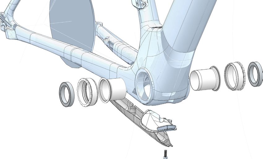
English

 Cannondale Supplements                                                  CONTENTS
 This manual is a “supplement” to your Cannondale
 Bicycle Owner’s Manual .                                Identification........................................... 2
 This supplement provides additional and important
 model specific safety, maintenance, and technical       Safety Information.............................. 3-9
 information. It may be one of several important
 manuals/supplements for your bike; obtain and
                                                         Technical Information.................... 10-28
 read all of them.
                                                         Replacement Parts...............................29
 Please contact your Authorized Cannondale Dealer
 immediately if you need a manual or supplement,         Ebike Pre-Ride Checklist.....................30
 or have a question about your bike. You may also
 contact us using the appropriate country/region/        Ebike Maintenance................................31
 location information.
                                                         Cleaning.................................................. 32
 You can download Adobe Acrobat PDF versions of
 any manual/supplement from our website: http://
 www.cannondale.com.

 Contacting Cannondale
 Cannondale USA
 Cycling Sports Group, Inc.
 1 Cannondale Way, Wilton CT, 06897, USA
 1-800-726-BIKE (2453)
 Cycling Sports Group Europe B.V
 Mail: Postbus 5100
 Visits: Hanzepoort 27
 7570 GC, OLDENZAAL, Netherlands
 service@cyclingsportsgroup.com
 International Distributors
 Consult our websIte to identify the                     Drive System
 appropriate Cannondale Dealer for your
 region.
                                                         MANUFACTURER’S INSTRUCTIONS - In
 Your Cannondale Dealer                                  addition to this supplement, you must read and
                                                         follow the manufacturer’s instructions for all
 To make sure your bike is serviced and maintained       components of the drive-assist system:
 correctly, and that you protect applicable
 warranties, please coordinate all service and            Drive Unit                   Battery
 maintenance through your Authorized Cannondale
 Dealer.                                                  Display/Control Unit         Charger

  NOTICE                                                 Manufacturers’ instructions contain important
                                                         operations, service and maintenance
  Unauthorized service, maintenance, or repair           information.
  parts can result in serious damage and void your
  warranty.

137377 Rev 1.                                        1
SuperSix EVO Neo - Owner’s Manual Supplement
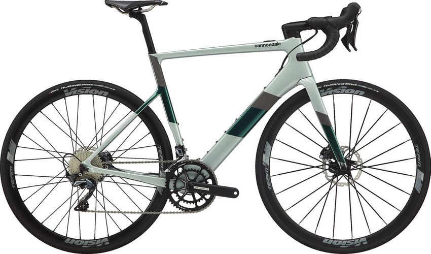
IDENTIFICATION
Parts of Your Ebike
2
1 5
3b
3a
9
7
10
8
4
6
Identification Actual bike appearance will differ.
1. X35 Rear Hub Drive Unit ** 4. Bottom Bracket Cover 9. Rear Cassette
2. iWoc® ONE 5. Charger/Battery Port 10. Bike Serial Number Location
(drive interface) 6. PAS Wheel Sensor **
3a. Battery (internal)** 7. Drive Unit Cable Guard
3b. Battery (external)** 8. Front Chain Rings
Serial Number Record YOUR Serial Number here:
The serial number is located on downtube.
It is a 7-character code. Use this serial
number to register your bike.
________________________________________
To register your bike: go to the
Product Registration section of our
website at www.cannondale.com
137377 Rev 1. 2
SAFETY INFORMATION

 Intended Use                                       In all modes/levels, the drive-assist system
                                                    power reduces progressively and cuts off as
                                                    the bike reaches a the maximum allowable
                     The intended use of all
                                                    speed. The drive-assist re-engages when
                     models is
                                                    speed drops below the maximum allowable
                     ASTM CONDITION 1,
                                                    speed as long as the pedals are turning.
                     High-Performance
                     Road.                          Whenever the drive-assist system is turned
                                                    OFF, you can pedal the bike normally. The
                                                    drive system will not engage.

 What is an Ebike?
 Electric bikes, also known as “E-Bikes”
 are bicycles equipped with an electric              Understand your bike, its drive-assist
 pedal assist drive system. An E-Bike IS             system and the intended use of both.
 NOT a moped or motorcycle. Ebike share              Using your bike the wrong way is
 components common with pedal-only bikes.            dangerous.
 What is a Drive System?                             Please read your Cannondale Bicycle
 The drive-assist system consists of a drive         Owner’s Manual for more information
 unit, a battery, a computer control, and            about Intended Use and Conditions 1-5.
 various electronic components (harness
 wires, sensors, and switches). There are
 many different drive-assist systems for
 differing uses and bike types. Likewise
 there are various drive-assist system              Servicing
 manufacturers (Shimano, BOSCH, Bafeng,
 Yamaha, etc.)
 How does the Drive System work?
                                                     This supplement may include procedures
 It is important to know that when the drive-        beyond the scope of general mechanical
 assist system is turned ON, the drive unit          aptitude.
 engages to provide power only while you are
 pedaling.                                           Special tools, skills, and knowledge may
                                                     be required. Improper mechanical work
 The amount of power provided by the drive           increases the risk of an accident. Any
 unit depends on your pedaling force and             bicycle accident has risk of serious injury,
 the assistance mode/level you set with the          paralysis or death.
 handlebar control unit. At anytime, if you
 stop pedaling, the drive-assist will dis-           To minimize risk we strongly recommend
 engage.                                             that owners always have mechanical
                                                     work done by an Authorized Cannondale
                                                     Dealer.

137377 Rev 1.                                   3
SuperSix EVO Neo - Owner’s Manual Supplement

 Important Composites                                Inspection & Crash Damage
 Message                                             Of Carbon Frames/Forks

   Your bike (frame and components) is                After A Crash Or Impact:
   made from composite materials also
   known as “carbon fiber.”                           Inspect frame carefully for damage. See
                                                      PART II, Section D. Inspect For Safety in
   All riders must understand a fundamental           your Cannondale Bicycle Owner’s Manual.
   reality of composites. Composite
   materials constructed of carbon fibers             Do not ride your bike if you see any sign
   are strong and light, but when crashed or          of damage, such as broken, splintered, or
   overloaded, carbon fibers do not bend,             delaminated carbon fiber.
   they break.                                        Any of the following may indicate a
   For your safety, as you own and use the            delamination or damage:
   bike, you must follow proper service,              •     An unusual or strange feel to the
   maintenance, and inspection of all the                   frame
   composites (frame, stem, fork, handlebar,
   seat post, etc.) Ask your Cannondale               •     Carbon which has a soft feel or
   Dealer for help.                                         altered shape
   We urge you to read PART II, Section D.            •     Creaking or other unexplained
   “Inspect For Safety” in your Cannondale                  noises,
   Bicycle Owner’s Manual BEFORE you
                                                      •     Visible cracks, a white or milky color
   ride.
                                                            present in carbon fiber section
   You can be severely injured, paralyzed
                                                      Continuing to ride a damaged frame
   or killed in an accident if you ignore this
                                                      increases the chances of frame failure,
   warning.
                                                      with the possibility of injury or death of
                                                      the rider.

                                                     No Child Seats or Trailers

                                                     Child seats and trailers or racks can not be used and
                                                     are not allowed to be used with your Cannondale
                                                     E-Bike.

137377 Rev 1.                                    4
Compliance/Regulation                                     Operation

  YOU MUST OBEY ALL LOCAL LAWS &                           ALWAYS WEAR AN APPROVED BICYCLE
  REGULATORY REQUIREMENTS - It is your                     HELMET AND ALL OTHER PROTECTIVE
  responsibility to identify and follow all local          GEAR (e.g. GLOVES, PADS, AND CYCLING
  laws and regulations necessary for legal                 SHOES).
  compliance. Compliance with local regulation
  is critical to the safety of a rider and others          IMPORTANCE OF PRACTICE & RIDER
  where the bike is used.                                  TRAINING - Before you ride this bike, practice
                                                           riding in a safe area free from hazards.
  Here are some important specifications                   Take time to learn to bike’s controls and
  related to compliance with local laws:                   performance. Practice the controls and gain
                                                           the experience necessary to avoid the many
  VEHICLE CLASS - A definition (California, USA)           hazards you will encounter while riding.
  of the different types of E-Bikes, E-Bike labeling
  and legal use areas, including any required              DO NOT RIDE “HANDS-OFF - Keep you hands
  additional equipment, registration, and                  on the handlebars when riding the bike. If
  applicable rider age restrictions.                       you remove your hands from the handlebar
                                                           while riding, you can lose control of the
  VEHICLE CATEGORY - A definition of the                   bicycle and crash.
  European Union of the different types of
  E-Bikes, who and where they may be used,                 CHANGING THE ASSISTANCE LEVEL WHILE
  necessary additional equipment such as                   RIDING - Changing the drive-assistance
  lighting and signaling devices as well as any            level while riding will increase or decrease
  necessary insurance and licensing.                       the acceleration of the bike. You should
                                                           anticipate this change in speed and react
  MINIMUM OPERATOR AGE - A minimum age                     appropriately depending on the riding
  require-ment for a rider of the E-Bike. This             conditions. (such as on slippery trails, tight
  restriction as well as speed and additional              turns, or unstable or uneven surfaces). Set
  equipment requirements (light, helmets,                  assistance level to “ECO” (lowest assist) or
  license plates, signal lamps, etc.)                      “OFF” before descending technical trails, (e.g.
  Follow any state or local laws for any minimum           tight downhill switchbacks).”
  age restrictions for E-Bikes.                            WHEN NOT RIDING - TURN THE DRIVE
  Ask your local Authorized Cannondale Dealer              SYSTEM OFF TO PREVENT UNAUTHORIZED
  for more information about operating an                  USE.
  electrically assisted pedal bicycle in your area.        DO NOT RIDE THE E-BIKE WITHOUT THE
                                                           BATTERY. MAKE SURE THE BATTERY IS
                                                           FULLY CHARGED BEFORE EVERY RIDE. This
                                                           will help ensure adequate battery power for
                                                           necessary lighting and the drive system.
                                                           DO NOT REMOVE ANY LIGHTING OR
                                                           REFLECTORS AND DO NOT RIDE IF THEY DO
                                                           NOT WORK.
                                                           DO NOT ALLOW CHILDREN TO OPERATE OR
                                                           COME INTO CONTACT WITH E-BIKE OR ITS
                                                           PARTS.
                                                           ONLY TURN THE DRIVE SYSTEM ON WHEN
                                                           YOU ARE SEATED READY TO RIDE.
                                                           (continued)

137377 Rev 1.                                          5
SuperSix EVO Neo - Owner’s Manual Supplement

   (Operation continued.....)                             (Operation continued.....)
   ACCIDENTAL ACTIVATION - Always                         YOUR INSURANCE POLICIES - Your
   disconnect battery from the bike before                insurance policies (e.g. liability, property
   working on the bicycle. If you transport               and injury) may not provide coverage for
   the bike by car or plane follow/obey local             accidents involving the use of this bicycle. To
   regulations regarding transportation a                 determine if coverage is provided you should
   bicycle with drive system battery. Accidental          contact your insurance company or agent.
   activation of the bicycle drive system can             Also, make sure your speed e-bike is insured
   result in serious injury.                              and registered according to the local laws.
   Wired System Control: If the drive system              RIDE SENSIBLY, RIDE SAFELY AROUND
   control device is detached from the mount              OTHERS - The application of power by means
   or the cables are disconnected to damaged,             of the electric motor assist means that riders
   the drive system will automatically shut off. If       can reach high speed. Riding faster increases
   this happens you will have to stop the bike,           the risks of serious accidents.
   turn the system off , re-attach the computer
   to the base, and then turn the system back on          Watch out for other vehicles, cyclists,
   to resume.                                             pedestrians, and animals where you ride.
                                                          Always operate under control and at a safe
   Wireless System Control: In wireless control           speed. Others may not be aware of you. It is
   systems, the operation of the drive system             your responsibility to anticipate and react to
   is controlled using radio frequencies,                 avoid accidents.
   without physical attachment. Therefore,
   activation ON/OFF is determined by                     E-BIKES ARE HEAVIER THAN ORDINARY
   software programming. Please consult the               BIKES - Always park the bike in a suitable safe
   manufacturer’s instructions for information on         area away from children, cars or animals that
   preventing accidental activation or re-starting        may come into contact with it. Park the bike
   the drive system in the event of a recovering          so that it cannot fall over possibly resulting in
   from a drive system fault.                             injuries.

   DO NOT RIDE THE E-BIKE WITHOUT THE                     DO NOT RIDE INTO OR ATTEMPT TO RIDE
   BATTERY. MAKE SURE THE BATTERY IS                      THROUGH WATER OR SUB-MERGE ANY
   FULLY CHARGED BEFORE EVERY RIDE. This                  PART OF THE BIKE. If you ride through
   will help ensure adequate battery power for            water you can lose control of the bike or the
   necessary lighting and the drive system.               drive-assist system can become disabled or
                                                          damage.
   DO NOT REMOVE ANY LIGHTING OR
   REFLECTORS AND DO NOT RIDE IF THEY DO
   NOT WORK.                                              You can be severely injured, paralyzed
   DO NOT ALLOW CHILDREN TO OPERATE OR                    or killed in an accident if you ignore this
   COME INTO CONTACT WITH E-BIKE OR ITS                   message.
   PARTS.
   ONLY TURN THE DRIVE SYSTEM ON WHEN
   YOU ARE SEATED READY TO RIDE.
   (continued)

137377 Rev 1.                                         6
Batterys & Chargers
                                                                 CHARGING - Bring indoors and allow to reach room
                                                                 temperature before charging. Make sure charger and
         DANGER                                                  A/C outlet are the same voltage.

                                                                 Locate both charger and battery indoors, in a clean,
  The battery pack voltage must match the battery
                                                                 dry area with good ventilation to charge. Make sure
  pack charging voltage of the charger. Otherwise,
                                                                 the area is free from combustibles to avoid fire from
  there is risk of fire and explosion.
                                                                 sparks or overheating. Keep charger ventilation
                                                                 openings unobstructed. Do not cover the charger
                                                                 or the battery.

                                                                 Disconnect the battery from the charger unit when
                                                                 fully charged. Do not leave a fully charged battery
  REPLACEMENT - Only use the battery pack
                                                                 connected to the charger. Unplug the charger from
  and charger indicated in the Secifications of this
                                                                 the wall outlet when not in use.
  supplement. Do not use other batteries or chargers.
  Do not use the charger to charge other batteries.              Maintain the battery and the charger as directed by
                                                                 the manufacturer’s instructions.
  PREVENT DAMAGE - Do not drop the battery or
  charger. Do not open, disassemble, or modify the               DISPOSAL- Battery pack/charger contain regulated
  battery or charger. No user serviceable parts inside.          materials and must be disposed/discarded in
                                                                 accordance with national and/or local laws. Do
  Keep the battery out of intense sunlight. Keep away
                                                                 not discard the battery/charger into fire, water or
  from heat. Heat will damage the battery.
                                                                 ordinary household waste/garbage. Take to a waste
  Keep battery away from paper clips, coins, keys, nails,        facility/recycler.
  screws or other small metal items, to prevent shorting
  exposed battery contacts. Shorting battery contacts
                                                                                    +

                                                                                                 +
  can cause severe burns, fire, or explosion.

  STORAGE & TRANSPORTATION - When the battery is
  not in use in the bicycle, its transportation is subject
  to hazardous materials regulation. Special packaging
                                                                 FAILURE TO OBSERVE THESE WARNINGS CAN
  and labeling requirements may exist. Contact local
                                                                 RESULT IN ELECTRICAL FIRES, EXPLOSION, OR
  authorities for specific requirements. Never transport
                                                                 SEVERE BURNS OR ELECTROCUTION.
  a damaged battery. Insulate battery contacts before
  packaging. Package battery inside a shipping
  container to prevent damage.

  The battery must be removed before flying and may
  be subject to special handling by the air carrier.

137377 Rev 1.                                                7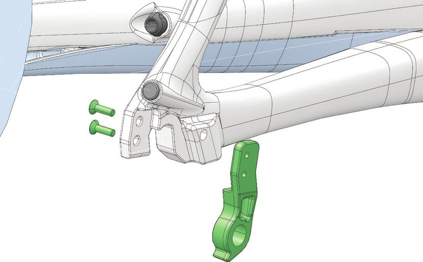
SuperSix EVO Neo - Owner’s Manual Supplement

 Mounting an External Battery                      Commuting

                                                   EQUIPMENT - Any bicycle Including
   Do not attach any external battery to the
                                                   an drive-assisted bike (ebike) must
   down tube water bottle location.                be properly equipped for commuting
   The water bolt bosses are not intended          including any legally required lights, signals,
   to carry the weight of a battery.               and registrations. Ask your Authorized
                                                   Cannondale Retailer if commuting is within
   If you ignore this warning, attaching an        the scope of your bike’s intended use
   external battery to this location could         and if your bike is properly equipped for
   damage the frame and/or detach from             commuting.
   the frame while riding, resulting in an         DANGERS - Operating an E-bike as a
   accident serious injury, paralysis or           commuting vehicle is no less dangerous than
   death.                                          an ordinary pedal bike or automobile. E-Bikes
                                                   are certainly not designed to protect you in
                                                   a crash. Do not assume the bike or its drive
                                                   capability will protect you or keep you from
                                                   being involved in a serious accident.
                                                   NIGHT RIDING- Riding at night on a E-Bike or
                                                   pedal-only bikes is very hazardous.
                                                   Read the topic “Riding at Night” in your
                                                   Cannondale Bicycle Owner’s Manual now
                                                   for more information on the many hazards of
                                                   riding at night.
                                                   You must operate with a very high degree
                                                   of awareness and precaution to only
                                                   reduce the risk of death or serious injury.

137377 Rev 1.                                  8
Disc Brakes on Road Bikes Water Bottle & External
Batteries
Side impacts to a water bottle or external
Relative to conventional rim brakes, disc battery can result in damage to threaded
brakes are less affected by water, do not inserts due to the leverage on a very small
wear or heat the rims and therefore are area. In a crash, certainly the last thing
more consistent. Disc brakes also may be you should be worried about is saving the
more powerful. threaded inserts in your frame. However,
when you are storing or transporting your
To minimize risk of injury or accidents:
bike, take steps to prevent situations where
• Understand that road bikes have a a water bottle may be hit or bumped by
relatively small tire contact patch a strong force that would cause damage.
(part of the tire that touches the Remove bottle and cage when you are
road). In order to apply the brakes packing your bike for travel.
safely and effectively, you may
Periodically check the attachment of the
need more or less braking force in
bottle cage and any external battery; tighten
different situations. You need to
the cage bolts if necessary. Don’t ride with
take into account various road and
a loose bottle cage. Riding with loose cage
weather conditions that can affect
bolts can produce a rocking motion or
traction.
vibration of the attached cage. A loose cage
• Disc brakes are excellent, but not will damage the insert and possibly lead to
some kind of magic. Take some time the inserts to pull out.
riding your new disc brake road bike It may be possible to repair a loose insert,
in lower risk circumstances to get or install another insert only if the frame is
used to the feel and performance of undamaged. Replacement requires the use
the disc brakes and tires. of a special tool. If you notice damage to the
threaded insert, please ask your Cannondale
You can be severely injured, paralyzed Dealer for help.
or killed in an accident if you ignore this
message.
137377 Rev 1. 9SuperSix EVO Neo - Owner’s Manual Supplement
TECHNICAL INFORMATION
Frame Specifications
Item Specification
Drive System Ebikemotion® X35 M1-C
Battery (internal) Ebikemotion® X35 B1-C
Battery (external), Range Extender (optional), Mount Seat Tube Only
Drive-Assist Owner's Manual https://www.ebikemotion.com/web/
Head Tube SM, MD: 1-1/8 in - 1-1/4 in, LG: 1-1/8 in - 1-3/8 in
Headset SM, MD: Integrated, 1-1/8 in - 1-1/4 in
LG: Integrated, 1-1/8 in - 1-3/8 in
Bottom Bracket: Type/Width T47/73 mm
Front Derailleur Braze-On
Seat Post: Dia./Binder 27 KNØT/Internal Wedge
Min. Seat Post Insert 65 mm
Max. Seat Post Insert Measure, See page 18.
Tire Size x Max. Tire Width 700c x 26mm
Brakes: Mount Type / Min./Max. Rotor Dia. RR: Flat Mount/160 mm/160 mm
FR: Flat Mount/140 mm/160 mm
Brake Rotor Compatibility Flat 6-Bolt rotors only (i.e., non-recessed mounting)
(e.g., Shimano SMRT-86 is not compatible)
Axles: Type/Length RR: EBM X35 Axle
FR: Speed Release TA Double Lead/100x12mm/119 mm
Length
DT Port Di2 junction box: HBar-end 3-port or stem mount 3-50-
5 port only, not in DT.
Water Bottle Mounting Bolts Maximum Length: 10 mm
Intended Use 1 ASTM CONDITION 1: High Performance Road
Max. Weight Limit: Total (Rider+All Equipment) 285 lbs/129kg
No Modification
DO NOT MODIFY THIS BICYCLE/DRIVE SYSTEM/ IN ANY WAY FOR ANY REASON. Doing so
can result in severe damage, faulty or dangerous operating conditions, or violation of local laws.
Dealers and Owners MUST NOT change, alter, or modify in any way the original components of
the bicycle or drive-assist system (e.g. the specified sizing of the attached gear ratios (front/rear
chain rings) ).
Attempts to “hot-rod” or “improve” the speed of the bike are dangerous to the rider. Use only
specified Cannondale and/or manufacturer drive-assist service and replacement parts.
137377 Rev 1. 10Drive System Specifications
Platform / Region
Supersix EVO NEO / EU US
Specification
Model Code C66150M C66250M C66350M C66150M C66250M C66350M
SuperSix SuperSix SuperSix SuperSix SuperSix SuperSix
Model Name EVO EVO Neo EVO Neo EVO EVO Neo EVO Neo
Neo 1 2 3 Neo 1 2 3
EPAC Type2 / E-Bike Class3 N/A Class 1
EPAC according to EN 15194 N/A
Range Extender Ebikemotion® X35 250Wh Ebikemotion® X35 250Wh
Display N/A N/A
Max. Power, Continuous 250 W 250 W
Max. Speed 25 km/h 20 mph
Max. Weight, Rack N/A N/A
EPAC Max. Weight 11.3 kg 12.4 kg 12.4 kg 25.0 lbs. 27.4 lbs. 27.3 lbs.
1
ASTM F2043
2
2006/42/EC (EU)
3
AB 1096 (USA)
Ebikemotion® Drive System Manuals
The following internet links will direct you to the drive manufacturer’s website and a specific user
manual or quick guide you will need to read and consult:
URL LINK TO
https://www.ebikemotion.com Drive manufacturer, home web page.
Manual for the drive system interface device
http://iWocONE-Quick-User-Guide
located on the top tube.
Manual for the rear hub drive unit, and the rear
http://User-Guide-X35-Connection+Mount
wheel and electrical connection.
Maintainance and Care manual for the X35 Drive
http://User-Guide-X35-Care+Maintenance
System
Periodically, check back with the manufacturers’ webite for revisions and/or additions to drive
system manuals.
137377 Rev 1. 11SuperSix EVO Neo - Owner’s Manual Supplement
Geometry
B
P
A
G
75 mm
F O
E D
K
J
L M
I
H N
Dimensions = centimeter/inches
Item Size S M L
A Seat Tube Length 47.7/18.8 51.5/20.3 53.6/21.1
B Top Tube Horizontal 53.4/21.0 54.6/21.5 55.7/21.9
D Head Tube Angle 71.2° * 73.0°
E Seat Tube Angle Effective 73.7° * *
F Standover 75.8/29.8 78.8/31.0 80.8/31.8
G Head Tube Length 13.2/5.2 15.4/6.0 16.4/6.5
H Wheelbase 100.6/39.6 101.8/40.1 100.2/39.4
I Front Center 59.8/23.5 61.1/24.0 59.4/23.4
J Chain Stay Length 41.8/16.5 * *
K Bottom Bracket Drop 7.2/2.8 * *
L Bottom Bracket Height 27.1/10.6 * *
M Fork Rake 5.5/2.2 * 4.5/1.8
N Trail 5.8/2.3 * 5.8/2.3
O Stack 53.4/21.0 55.4/21.8 57.4/22.6
P Reach 37.8/14.9 38.4/15.1 38.9/15.3
Head Tube Height 37.5/14.8 * *
* Indicates same.
All Specifications subject to change without notice.
137377 Rev 1. 12Bottom Bracket - T47 / 73 mm
2
3
3
NON-DRIVE SIDE
40-50 N·m 73 mm
DRIVE SIDE 5 1
Identification
4
1. Frame BB Shell Park Tool BB-T47
2. T47 BB System
3. Bearing
4. BB Cover
6
5. Chainstay Cable Cover
6. Cover Screw
Servicing
Prior to replacement of any parts in the BB shell system, thoroughly clean the inside surface of
the bottom bracket shell with a clean dry shop towel.
NOTICE
To avoid serious damage to the frame, follow the manufacturer’s instruction for assembly and
installation of the bearing system. Use the specified bottom bracket tools when servicing.
Consult with your Cannondale Dealer on the quality and compatibilty of any proposed
replacement component. Do not use chemical solvents to clean. Do not remove frame
material or use surfacing tools on bottom bracket shell. Frame damage, caused by improper
components, component installation or removal is not covered by your warranty.
137377 Rev 1. 13SuperSix EVO Neo - Owner’s Manual Supplement
Routing
5 CC
VERY IMPORTANT: 2 N·m
Route housings shown under the 8 mm Max.
installed BB shell with large curva-
ture, thus preventing binding and RB
cable drag.
6
See WARNING, page 8.
4
2
NGL
I-2
1 2 N·m
RB 9
RD
M5 X 10 Max.
3
FD
NOTICE
CP Do not use water bottle mounting
DU
bolts longer than the maximum
specifed. Longer bolts will protrude
into the down tube and damage the
Sen internal battery.
7 8
8
Identification
1. Battery, External (optional) 7. Chainstay Cable Guard RB - Rear Brake Line
2. Battery, Internal 8. Bottom Bracket Cover RD - Rear Derailleur Housing
3. Charge Port 9. Water Bottle Mounting Bolts DU - Drive Unit Cable
4. Water Bottle FD - Front Derailleur Housing
5. iWoc® ONE CP Charge Ports Cable
(drive interface) CC - iWoc® ONE Cable
6. DT Cable Guide
Please Note: Do not attempt to work on the cable routing yourself. Due to the complex nature of
the parts and the level of disassembly required to gain access, have any repairs or replacements
of the battery, cables or hoses parts identified performed by an authorized Cannondale e-bike
service center.
137377 Rev 1. 14Internal Battery
• To prevent damage to the battery
it is very important to observe the
specified maximum tightening torques 7
2 M5
of the clamp and mounting bolts. 5
2 N·m
Max.
The three clamps are positioned on
RB the battery for alignment with the
frame holes before installation, and 6
the clamp spacing vary between
3
differing frame sizes.
• Clamps are not to be positioned at the 4
water bolt DT frame holes. 2 M4
2 N·m
• See Replacement parts for service Max.
kits .
2
Cross-Section View
(installed)
1
NO PINCH
8
NOTICE
Take care to prevent pinching or crushing
of the brake hose, derailleur housings
between upper portion of the clamp and
inner DT frame wall.
Identification
1. Battery, Internal 4. Clamp Bolt 7. Upper Battery Cables
2. Clamp 5. Mounting Bolt 8. Lower Battery Cables
3. 3M™ Tape 6. T-Washer
137377 Rev 1. 15SuperSix EVO Neo - Owner’s Manual Supplement
Rear Wheel
The drive unit manufacture’s instructions
To install:
contain important details about handling
parts of the drive system. Read those
instructions now. 1. Turn OFF the drive system. See
manufacturers‘ instructions.
2. Secure the bicycle in a bicycle work
stand with the rear wheel off the ground.
To prevent serious injury in the event of
3. Position the rear wheel into the dropouts.
accidental activation, turn the drive system
OFF before performing any work. 4. Align the axle washers protrusions with
the dropout slots, as shown in the figure
and install it onto each side of the axle.
NOTICE
5. Finger tighten both axle nuts.
Take measures to protect the cables and
connectors from damage while the wheel is On the power cable side of the rear hub,
removed. make sure the cable is aligned in the slot
as shown. Make sure the cable will not
To remove: be pinched or crushed when tightening
the axle nut.
If the rear wheel must be removed in case
of a tire or tube replacement, the following 6. Tighten both axle nuts to the specified
must be observed in the order presented: torque. See hub instructions.
7. Re-connect the battery and hub cable
1. Turn OFF the drive system. See
ends.
manufacturers‘ instructions.
8. Install the chainstay power cable cover
2. Secure the bicycle in a bicycle work
with cables and tighten the screws to the
stand with the rear wheel off the ground.
specified torque.
3. Loosen the guard screws and shift the
chainstay cable guard back and removed
over the screws and remove it.
4. Disconnect the battery cable and drive
unit cable connectors.
5. Loosen the drive unit axle nuts. An open
end wrench or and 8mm allen wrench
can also be used.
Dropouts are designed so that the nuts
and washers do not need to be comple-
tely removed to assemble/disassemble
rear wheel.
6. Carefully remove the wheel from the
dropouts.
137377 Rev 1. 164
5
6 3
M4 x 12 mm
2
2 M4
1 N·m
M4 x 8 mm 1
2 M4
1 N·m
NOTICE
Ensure that the chainstay
cable cover (1) is capturing
the power cable at the
dropout end and is not
oriented towards brake
rotor.
Do not ride the bike without
the chainstay cable guard.
Replace it if missing or
damaged.
Identification
1. x35 Drive Unit (rear hub) 4. Axl;e Nut
2. Chainstay Cable Cover 5. Battery Connector
3. Axle Washer 6. Drive Unit Connector
137377 Rev 1. 17SuperSix EVO Neo - Owner’s Manual Supplement
Removing the internal battery
Front Derailleur Mount
4 3
The internal battery must only be service by a
professional bike mechanic. 1
1. Disassemble the headset cap so that
the fork may be lowered slightly within
1
the headtube. This is required to enable
adequate cable slack.
2. Remove the two screws and open the (Mechanical shift shown)
down tube cable housing guide on the
downtube, to enable cable slack.
3. Remove the screws that retain the top
tube mounted iWoc® ONE.
The front derailleur mount is bonded to the frame.
4. Remove the bottom bracket cover and It is a “braze-on type.”
chainstay cable guard.
Do not attempt to remove the mount.
5. Remove the four screws and open the
When using a mechanical FD system or SRAM
charge port from the frame opening.
Etap, make sure the frame plug is installed to
6. Pull the upper cables wire thru the cable prevent the intrusion of water or debris into the
frame.
guide hole in the DT and unplug the
connections. When using Di2 Systems, use the Di2 Cable Plug.
7. Remove the crankset and remove the BB
shell.
8. Remove the rear wheel
9. Unplug the drive unit.
10. Open the charger plug
11. Pull the derailleur housing up thru the
charger plug hole to free the space for
the battery
12. Pull the battery down and out of the
downtube.
137377 Rev 1. 18Rear Derailleur Mount Headtube Steering Angle
Underside of headtube.
2
2
2
2 N·m 1
1
LI-2
NG
0°
55° 55°
1. RD Mount 2. M3 X 10 Screws
3
To replace:
Remove the rear wheel.
Remove the mounting screw(s) and remove the old
hanger from the dropout.
Clean the area around the dropout and inspect the 1. Fork Stop Pin 2. Limits
frame carefully for any cracks or damage. If you Head Tube Stop 3. Steering Angle
find damage have the frame inspected by your
Cannondale Dealer .
If the dropout is un-damaged, apply a light film
of grease between the frame and mount. This NOTICE
will help minimize any noise or “creaking” that
might result from very slight movement between Do not force the steering past the stop
the dropout and mount during movement of the points.
derailleur.
If the front end steering of the bikes is
Slide the new hanger onto the dropout. over-loaded (due to e.g. a handlebar
Clean and apply Loctite® 242 (or medium strength strike, a crash, etc.) damage to the frame,
thread lock) to the screw threads and tighten to the fork or pin may result.
specified torque.
This type of damage is not covered by the
limited warranty.
137377 Rev 1. 19SuperSix EVO Neo - Owner’s Manual Supplement
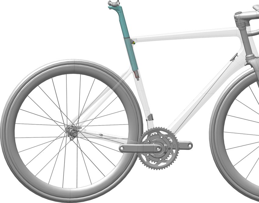
Seat Post
Installation & Adjustment Minimum Insert
Before installing: The minimum insert depth the seat post must be
inserted into the frame is 65mm.
• Use a clean shop towel to wipe out any
residual carbon gel paste from the inside the
seat tube.
Maximum Insert
The total length of seat post that may be inserted
• Apply fresh carbon friction gel to the seat will vary with the frame size and should be checked
post and place a little bit inside the seat tube. in each frame.
• Make sure the seal is in good condition and in To check, carefully slide a seat post into the frame
place on the seat post. until it stops; then lift it up 5mm.
To adjust:
NOTICE
1. Insert the prepared seat post into the frame.
Maintain the specified minimum insert. A seat post should not be bottomed out inside
the frame at any time. Have your Cannondale
2. Set the saddle height. Dealer size the seat post appropriately.
3. Insert 4 mm hex through the underside seat
tube opening as shown.
4. Tighten the binder screw to the specified
torque.
THE SEAT POST MUST ONLY BE CUT BY A
5. Slide the seal against the frame.
PROFESSIONAL BIKE MECHANIC. Incorrectly
5. If saddle angle adjustment is required, loosen cutting the seat post can result in damage
the saddle clamp bolts, adjust the saddle, and leading to an accident.
tighten to the specified torque.
For more information about carbon fiber seat
NOTICE posts, see also “Care and Maintenance of Carbon
Fiber Seat Posts” in your Cannondale Bicycle
• Do not use any spray cleaners or solvents
Owner’s Manual.
to clean. Use only a clen dry shop towel.
• Do not exceed the specified torque. If
you over-tighten the binder bolt, you will
damage the binder, seat post or the frame.
Maintenance
Periodically, remove the seat post and the clamp
assembly to clean, inspect for damage and renew
the application of grease and carbon gel.
See also, “Seat Binder Inspection.”
137377 Rev 1. 20Apply heavy grease between
sliding wedge and frame interface
Identification 1 to prevent creaking.
1. Saddle Clamp
2. Seat Post NG
LI-
3. Sliding Clamp 3 2
4. Seal
5. Di2 Battery
6. Battery Bracket CRB-GEL
7. Di2 Cable
6 N·m
2
3
4
CRB-
GEL
Apply
carbon paste to
65mm
entire length of the 6 N·m
inserted seat post CRB-GEL
Minimum Insert
CRB-GEL
5
6
Maximum Insert
5mm
Maximum Depth
7
137377 Rev 1. 21SuperSix EVO Neo - Owner’s Manual Supplement
Seat Binder Inspection
The internal seat binder system consists of a sliding clamp assembly and a nut base with a
double-side adhesive holding it to a special mating surface inside the seat tube. The sliding
clamp parts can be removed when the seat post is out.
Always clean the surfaces of the sliding clamp by wiping them with a clean dry lint-free shop
towel only. Do not soak the parts, as the internal washer is lubricated with grease. Solvents
will wash out the lubricant and the assembly will have to be regreased by disassembling it
completely.
NOTICE
If the nut base has become rotated, it should be removed and re-affixed to the frame. The process is
described in the Service Instruction for the parts kit. These instructions are not provided in this manual.
We reccommend that you have a Cannondale Dealer perform the replacement.
Please Note: During first assembly of the nut base, it is important to not push on the 4mm allen
when tightening onto the seatpost. This can disengage the adhesive tape before proper bonding.
A poor bond can lead to misalignment. The 3M™ VHB™ Tape 5980 is pressure sensitive.
To inspect 6. Check the condition of the clamp. The
seat post face and frame contact surfa-
1. To remove the seat post. See previous ces should be smooth. If they are not, the
page. clamp assembly should be replaced with
a new one.
2. To remove the sliding clamp, use a 4
mm hex key and turn grub screw slowly 7. Clean the parts and inside the seat tube
clockwise until the clamp is disengaged with a dry shop towel and re-apply grease
from the nut base. and carbon paste as indicated.
3. Use the 4 mm hex to push the clamp out 8. Returning the sliding clamp to the frame,
through the seat tube opening. using the 4 mm hex to guide it to the nut
base.
4. Look into the frame opening. Use a pen
flashlight. Check the position of the nut 9 Turn the grub screw counter-clockwise
base. See CORRECT next page. to engage the nut base. Make sure it is
enaged sufficiently to easily insert the
5. If the nut base is missing, or rotated or seat post into the seat tube.
damaged, a replacement is required.
This service should be performed by a
Cannondale Dealer.
137377 Rev 1. 222
LI-
(shown disassembled)
NG
Correct application
1 of carbon paste
2 and grease.
EL
4 B- G
CR
3
NGLI-2
5
The pressure sensitive adhesive
double-sided tape secures the
6 aligned nut base in the frame.
When applied the nut base and
frame should be very clean for a
good bond.
Ready to accept seat post.
This is CORRECT.
Identification
1. Sliding Clamp
2. Roll Pins (2X)
3. Washer
4. Grub Screw
5. Nut Base
6. Pressure Sensitive Adhesive Tape
This is INCORRECT. (Double-sided)
The nut plate is rotated.
137377 Rev 1. 23SuperSix EVO Neo - Owner’s Manual Supplement KNØT Stem Spacers Spacers can be flexed open to allow spacer assembly / disassembly without disconnecting cables. Bend spacer inwards to route cables through first slot, then route cables through the second slot. Assemble spacer on steerer tube. Spacers and stem have interlocking feature to ensure alignment. 137377 Rev 1. 24
English

  Hinge covers together and slide them over
  the stem body. Stem body and covers have
  interlocking features.

  Close right stem cover first, then rotate left
  stem cover in place and close around the
  stem body

  Assemble the stem covers with the M3 bolt
  (1Nm)

137377 Rev 1.                                      25
SuperSix EVO Neo - Owner’s Manual Supplement

                                                    KNØT / SAVE SystemBar

                                                                                                                     STEM     REACH
                                                                  G                                                 LENGTH
                                             A

                                                                                                                           DROP

                                                                                          E

                                   B1                                                                      F

                                                              L
                                                           -GE
          2                                          CRB
         5 N·m                                                                                                 C
                                                                                                                                           L
                                                                                                                                        -GE
                                                                                               2                                  CRB
                                                                                              5 N·m

                                                 1 N·m

                       B2
P                                        6
                                        2 N·m

                            (1X)                                                                       D
                                                                                                               2
                            (4X)                                                                            5 N·m
              H                                   7.5mm

                            (2X)
                                                  12.5mm

                                                                                                                       2
                                                                                                                     5 N·m

    KNØT & SAVE Shared Parts

                  ID                    Description                   Part Number
                  D                     K28018                        SystemBar Mounting Hardware
                  E                     K12018                        SystemBar Computer and Light Mount
                  F                     K12008                        SystemBar Computer and Light Insert
                  G                     K28039                        HGRM KNØT/SAVE Handlebar Plug
                  H                     K28000                        SuperSix Stem Spacers

    137377 Rev 1.                                                          26
Handlebar
Width
ID Description Part Number
(cm)
CP2650U1038 38
CP2650U1040 40
KNØT
CP2650U1042 42
CP2650U1044 44
A CP2600U1036 36
CP2600U1038 38
SAVE CP2600U1040 40
CP2600U1042 42
CP2600U1044 44
Stems
Stem Length Stem Rise
ID Description Part Number
(mm) (degrees)
CP2300U1080 80
CP2300U1090 90
CP2300U1010 100 - 17
CP2300U1011 110
CP2300U1012 120
B1 KNØT Stems
CP2250U1080 80
CP2250U1090 90
CP2250U1010 100 -6
CP2250U1011 110
CP2250U1012 120
K2804080 80
K2804090 90
K2804000 100 - 17
K2804010 110
SuperSix EVO K2804020 120
B2
KNØT Stem Covers K2803080 80
K2803090 90
K2803000 100 -6
K2803010 110
K2803020 120
CP2000U1080 80
CP2000U1090 90
CP2000U1010 100
-6
CP2000U1011 110
CP2000U1012 120
C SAVE Stems
CP2000U1030 130
CP2100U1080 80
CP2100U1090 90
+6
CP2100U1010 100
CP2100U1011 110
137377 Rev 1. 27SuperSix EVO Neo - Owner’s Manual Supplement
KNØT SystemStem
4 N·m
K35009
3mm
2
MAX.
5 N·m
55mm
7.5mm
12.5mm
• The KNØT stem supports internal brake hose and Di2 wire routing.
• Assembly of spacers is explained on the previous pages.
• Stem height may be set using combination of the 12.5mm and/or 7.5mm spacers.
• The maximum spacer stack height is 55mm. The example above depict 2x 12.5mm spacers and 4x
7.5mm spacers, resulting in 55mm.
• The KNØT stem is to be used only with a Cannondale SystemBar handlebar such as SAVE or KNØT
SystemBar.
• Use only the Cannondale SI Compression plug K35009.
Additional instruction at:
https://p.widencdn.net/w5njzq/134947-REV-1-CD-OMS-SAVE-KNOT-SystemBar
137377 Rev 1. 28REPLACEMENT PARTS
O
G LI-
2
NG
A
6 N·m
M6 V
H
I
CRB-GEL 2 M8
4-6 N·m K
2X 2 M3
2 N·m P M
J B
M5
2
M3 1 N·m 2 N·m R
Di2
eTap
S
water bottle bolts
J M5 10 mm
2 (max. length)
N
2 N·m
1 N·m
E
Y
P
2 M47
40-50 N·m C
F
D
QTY 3
T
FT
ID Part Number Description ID Part Number Description
A K26030 S6 EVO Internal Seat Binder M K32160 S6 EVO/CAAD13 DT Cable Guide
B K33009 Derailleur Hanger TA ST SS 070 N K32180 KNØT 27 Di2 Battery Mount
C K34100 S6 EVO Neo Battery Door O K26070 Seatpost Silicone Grommet
D K34120 NDS CS Power Cable Protector P KP449/ Rubber Brake Housing Grommets
-- KF115/ Carbon Seatpost Gel R K35028 1 1/4 Crb Headset No Crown Race
S K35038 1 3/8 Crb Headset No Crown Race
E K33080 Dropout Bolts M4x10mm Qty 2
Speed Release TA 100x12 2Lead
F K76050 X35 Battery Straps/Mounting Hrdw T K83019
P1.0 119mm
G K26050 KNØT 27 Rail Clamps and Hardware Speed Release TA 142x12 2Lead
-- K83029
HG 27 KNØT Crb Seatpost 330mm P1.0 165mm
K2601000
0 O/Set V K35058 SL Compression Plug with Top Cap
H
HG 27 KNØT Crb Seatpost 330mm
K2601015 -- KP197/SRM PF30 BB Cups & Bearings
15 O/Set
C1 27 KNØT Alloy Seatpost 330mm -- KB6180/ BB30 Bearing Blue (QTY 2)
I K2602015
15 O/Set -- K22037 BB30 Bearing Blue (QTY 24)
J K32170 S6 EVO Frame Grommets
Y K34130 Chainstay Protection Film
K K32030 S6 EVO Rim Di2 Headtube Wire Guide
137377 Rev 1. 29SuperSix EVO Neo - Owner’s Manual Supplement
EBIKE PRE-RIDE CHECKLIST
Before and After Each Ride:
• Clean and visually inspect the entire bike for cracks or damage. See “Inspect for
Safety” in your Cannondale Bicycle Owner’s Manual.”
• Make sure the battery is fully charged and mounted securely. Follow the drive system
charging instructions. Battery charge discharge capacity will decline with usage.
Have older battery replaced when is fails to charge within the time indicated, and/or to
provide power reliably.
• Test the drive-assist system, make sure the drive system functions normally.
• If your E-Bike model was equipped a lighting system, brake lights, headlights, tailights
and number plate illumination, make sure these lights are each functioning normally.
Make sure the number plate is clean and readable.
• Check the front and rear brake conditions, make sure they function normally.
• Check tire pressure and wheel conditions. Check tire pressure and the condition of
the wheels. Ensure the tires are not damaged and do not have excessive wear. Ensure
there are no broken or missing wheel parts and that the wheels are firmly attached via
secured skewers/axles.
• Confirm the drive chain condition is in good condition, is clean and well-lubricated.
Chain wear is greater compared with pedal only bikes. This requires frequent inspection
and replacement. Ensure the gears operate normally through the entire range.
• Check the bicycle brakes. Make sure they are working well. Brake system pad and disc
wear is greater compared with pedal only bikes. This requires frequent inspection and
replacement.
• Inspect condition of electrical cables (i.e. Kinks free, no signs of abrasive wear). Check
cable at dropout end when assembled properly will prevent cable from contacting brake
rotor.
Perform a pre-ride-check before and after each ride. Frequent checks are necessary to identify
and correct problems that can lead to an accident. Do not ride your bike if it does not operate
normally or has broken, damaged, or missing parts. Have any damage inspected and repaired by
your Cannondale Dealer before riding again.
You can be severely injured, paralyzed or killed in an accident if you ignore this warning.
137377 Rev 1. 30EBIKE MAINTAINANCE
Maintaining Your Bike Maintaining Your Bike’s
Drive System
1. Read your Cannondale Bicycle Owner’s
Manual for information on an owner’s
reposnsibility for the routine/ basic
inspection and maintenance of your bike. NOTICE
Drive-assist system components must
Consult with your Authorized Cannonda- only be serviced at an authorized service
le Dealer to create a complete main- center. This will ensure the quality and
tenance program for your riding style, safety of the drive-assist system.
components, and conditions of use.
Never attempt to open, remove drive
Follow the maintenance recommenda- system parts from the frame, or work
tions given by the component manufac- on them yourself. Other components
turer’s for the various parts of your bike. of the electric bicycle drive (e.g. drive
chain, front chain ring, rear cassette, rear
2. Recommended after the first 150 km, derailleur, crank arm) must be serviced by
bring your bike to your Authorized Can- an Authorized Cannondale Dealer.
nondale Dealer for an initial check-up. It
should include checks of the drive-assist Replacement parts must be identical to
system, drive chain condition, proper the original Cannondale specification for
shifting, accessories, wheels and tire the bike. Failure to replace components
condition, brakes, etc. This visit will help with original specification can result in
you establish a schedule for repeated serious overload or other damage to the
visits appropriate for how and where you drive unit.
ride.
Unauthorized opening or service of the
3. Every 1000 km, bring your bike in to drive unit will void the warranty.
your Authorized Cannondale Dealer for a
regular detailed inspection, adjustment,
and replacement of wear items across
the entire bike. Electrically powered-as-
sist cycle (electric bikes) can wear out
wheels, tires, drive chain, brakes, more
quickly.
137377 Rev 1. 31SuperSix EVO Neo - Owner’s Manual Supplement Cleaning When cleaning your bike, use a damp sponge or a soft brush with only a mild soap and water solution. Rinse the sponge often. Do not spray water directly on controls or drive system components. NOTICE Do not use a pressure washer or dry with compressed air. This will force contaminants into sealed areas, electrical connections/components promoting corrosion, immediately damaging, or result in accelerated wear. Keep water away from the electrical components. Make sure the bike is secured upright and can not fall over accidentally while you are cleaning it. Don’t rely on the kickstand. Use a sturdy portable bicycle wheel stand to hold the bike upright. 137377 Rev 1. 32
WWW.CANNONDALE.COM
© 2019 Cycling Sports Group
SuperSix EVO Neo Owner’s Manual Supplement
137377 Rev. 1

 CANNONDALE USA               CANNONDALE EUROPE                 CANNONDALE UK
 Cycling Sports Group, Inc.   Mail: Postbus 5100                Cycling Sports Group
 1 Cannondale Way,            Visits: Hanzepoort 27             Vantage Way, The Fulcrum,
 Wilton CT, 06897, USA        7570 GC, OLDENZAAL, Netherlands   Poole, Dorset, BH12 4NU
                              service@cyclingsportsgroup.com
 1-800-726-BIKE (2453)                                          +44 (0)1202732288
 www.cannondale.com                                             sales@cyclingsportsgroup.
                                                                co.uk
You can also read