E-SERIES OWNER'S MANUAL SUPPLEMENT - Cannondale Bicycles
←
→
Page content transcription
If your browser does not render page correctly, please read the page content below
130374

E-SERIES     L SUPPLEMEN
                        T
        MANUA
OWNER’S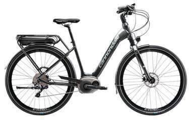
E-Series Owner’s Manual Supplement - 130374

              Contents                                                        About This Supplement
                                                                              Cannondale Owner’s Manual Supplements provide important model
                                                                              specific safety, maintenance, and technical information. They are
                                                                              not replacements for your Cannondale Bicycle Owner’s Manual.
Safety Information.........................................2                  This supplement may be one of several for your bike. Be sure to
                                                                              obtain and read all of them.
Parts of the E-Series Bike............................... 4

                                                                                                                                                       ENGLISH
                                                                              If you need a manual or supplement, or have a question about your
                                                                              bike, please contact your Cannondale Dealer immediately, or call
Operation........................................................... 5        us at one of the telephone numbers listed on the back cover of this
                                                                              manual.
Lithiumion battery pack................................12                     You can download Adobe Acrobat PDF versions of any Cannondale
                                                                              Owner’s Manuals or Supplements from our website: http://www.
BATTERY CHARGER..............................................16               cannondale.com/.

                                                                                                                                                       DEUTSCH
Maintenance....................................................18             Please note that the specifications and information in this manual
                                                                              are subject to change for product improvement. For the latest
HEADSHOK SUSPENSION FORK.......................... 20                         product information, go to http://www.cannondale.com

TECHNICAL INFORMATION..................................22                     Online E-Series Product Support
Keys	 .................................................................. 24   You may download a copy of this supplement and other manuals

                                                                                                                                                       FRANÇAIS
                                                                              and instructions available for your bike at: http://www.cannondale.
                                                                              com/manual_ebikes/
             This bike complies with EN 15194. EN14764 -
             Electrically Power Assisted Cycles (EPAC).                       Your Cannondale Dealer
                                                                              To make sure your bike is serviced and maintained correctly, and
                                                                              that you protect applicable warranties, please coordinate all service

                                                                                                                                                       NEDERLANDS
                                                                              and maintenance through your authorized Cannondale Dealer.

                                                                                NOTICE
                                                                                Unauthorized service, maintenance, or repair parts can result in
                                                                                serious damage and void your warranty.

 MODEL CODE            MODEL DESCRIPTION
 CM2038                MAVARO MENS HEADSHOK                                                                                                            ITALIANO
 CM2290                MAVARO MENS HEADSHOK ALFINE 8
 CF2293                MAVARO CITY HEADSHOK
 CF2294                MAVARO CITY HEADSHOK ALFINE 8
 CF2390                MAVARO WOMENS HEADSHOK
 CM2389                MAVARO MENS RIGID
                                                                                                                                                       Español

 CF2393                MAVARO WOMENS RIGID
 CM2394                TRAMOUNT 1
 CM2396                TRAMOUNT 2

                                                                                                                                                   1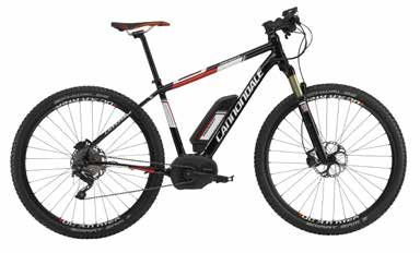
Safety Information
             Intended Use                                                                        WARNING
ENGLISH

             Your E-Series bike has an electric pedal assist drive system. It is not a
             moped or motorcycle. In EU countries, it is known legally as an “EPAC”       **INTENDED USE: This bicycle is intended to be used as a
             cycle or Electrically Powered Assisted Cycle.                                commuter bicycle. This bike complies with the requirements of
             The drive assist system consists of a drive unit, a battery, a computer      European Standard EN 15194, Electrically Power Assisted Cycles.
             control, and various electronic components (harness wires, sensors, and
                                                                                          The drive assist system is limited to a maximum continuous
             switches). Your E-Series bike does share components common with
                                                                                          power rating of 0,25 kW (250 W) and a maximum speed of
             pedal only bikes.
             It is important to know that when the assist system is turned ON, the        25Km/h, (15.5 mph).
                                                                                          NOT INTENDED: You must not ride this bike in automobile
DEUTSCH

             drive unit engages to provide power only while you are pedaling. The
             amount of power provided by the drive unit depends on your pedaling          traffic lanes. This vehicle must only be operated on paved
             force and the assistance mode/level you set with the handlebar control       surfaces that are legally open to commuter pedal bicycles. This
             unit. At anytime, if you stop pedaling, the drive assist will disengage.     bike is not for mountain biking use, jumping, or racing.
             In all modes/levels, the drive assist system power reduces progressively     YOU MUST FOLLOW ALL LOCAL LAWS: It is your responsibility
             and cuts off as the bike reaches a speed of 25 km/h, (15.5 mph), or          to identify and follow all local laws and regulations (including
             sooner if you stop pedaling. The drive assist re-engages when speed          fitting your bike with additional equipment) necessary to
             drops below 25 km/h, (15.5 mph) as long as the pedals are turning.           comply with local laws. Ask your Cannondale Dealer for more
FRANÇAIS

             Whenever the drive assist system is turned OFF, You can pedal the bike       information about operating an electrically assisted pedal
             normally. The drive system will not engage.                                  bicycle in your area.
                                                                                          DO NOT MODIFY THIS BICYCLE/FORK IN ANY WAY FOR ANY
              MAVARO                    INTENDED:For paved roads, gravel or dirt          REASON. Doing so can result in severe damage, faulty or
              ASTM CONDITION 2,         roads that are in good condition, and bike
                                                                                          dangerous operating conditions, or violation of local laws.
              General Purpose           paths.
                                                                                          IMPORTANCE OF PRACTICE & RIDER TRAINING - Before you
              Riding                    NOT INTENDED: For off-road or mountain
                                                                                          ride this bike, practice riding in a safe area free from hazards.
NEDERLANDS

                                        bike use, or for any kind of jumping.
                                                                                          Take time to learn to bike’s controls and performance. Practice
                                                                                          the controls and gain the experience necessary to avoid the
              TRAMOUNT                  INTENDED: for “limited” mountain bike
                                        use, riding only improved trails and surfaces
                                                                                          many hazards you will encounter while riding.
              ASTM CONDTION 3,
                                        without jumps or obstacles.                       DO NOT RIDE “HANDS-OFF - Keep you hands on and the
              Hardtails
                                        NOT INTENDED: for any jumping, very               handlebars when riding the bike. If you remove your hands
                                        aggressive cross-country/mountain bike            from the handlebar while riding, you can lose control of the
                                        riding, racing or stunts. Jumping or riding       bicycle and crash.
                                        over very technical, rough or unimproved          UNDERSTAND YOUR BIKE AND ITS INTENDED USE. USING
ITALIANO

                                        trails (roots, rocks, embankments) can result     YOUR BIKE THE WRONG WAY IS DANGEROUS.
                                        in serious damage to the frame or drive           Please read your Cannondale Bicycle Owner’s Manual for more
                                        system. Indications of such abuse would           information about Intended Use and Conditions 1-5.
                                        void applicable warranties.                       YOU CAN BE YOU SERIOUSLY INJURED, PARALYZED OR KILLED
                                        **EXCEPTION: This model must not be               IF YOU IGNORE THESE WARNINGS.
                                        used as a commuter bike until the proper/
                                        required accessories (reflectors, lighting, and
                                        locally required safety devices have been
Español

                                        installed by a professional bike mechanic.

             2
E-Series Owner’s Manual Supplement - 130374
Battery & Charger Locate both charger and battery indoors, in a clean, dry area
with good ventilation to charge. Make sure the area is free from
combustibles to avoid fire from sparks or overheating. Keep
WARNING charger ventilation openings unobstructed. Do not cover the
charger.
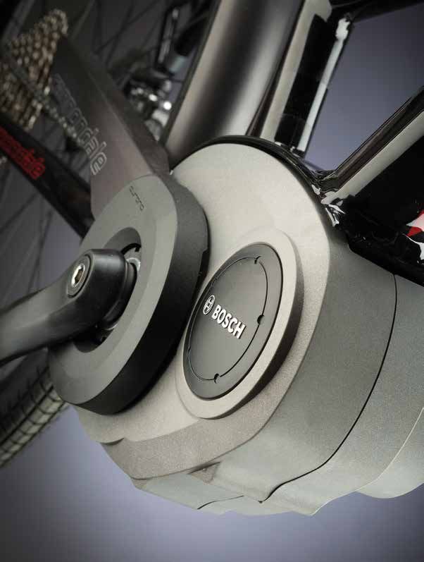
BOSCH INSTRUCTIONS - In addition to this supplement,
Disconnect the battery from the charger unit when fully charged.
you must read and follow the BOSCH battery and charger
Do not leave a fully charged battery connected to the charger.
ENGLISH
instructions. Go to: http://www.cannondale.com/manual_
Unplug the charger from the wall outlet when not in use.
ebikes/
DISPOSAL- Battery pack/charger contain regulated materials
REPLACEMENT - Only use the battery pack and charger
and must be disposed/discarded in accordance with national
indicated in the Specifications section of this supplement. Do
and/or local laws. Do not discard the battery/charger into fire,
not use other batteries or chargers. Do not use the charger to
water or ordinary household waste/garbage. Take to a waste
charge other batteries.
facility/recycler.
PREVENT DAMAGE - Do not drop the battery or charger. Do
DEUTSCH
not open or modify the battery or charger. No user serviceable
+
+
parts inside.
Keep the battery out of intense sunlight. Keep away from heat.
Heat will damage the battery.
TRANSPORTATION & SHIPPING - The battery of this bicycle is
Keep battery away from paper clips, coins, keys, nails, screws or
subject to transportation regulations for handling hazardous
other small metal items, to prevent shorting exposed battery
materials. The battery must be removed before flying and may
contacts. Shorting battery contacts can cause severe burns, fire,
be subject to special handling by the carrier.
or explosion.
FRANÇAIS
Failure to observe these warnings can result in electrical fires,
ACCIDENTAL ACTIVIATION - Always remove battery from bike
explosion, or severe burns or electrocution.
rack before working on the bicycle or if you transport the bike
YOU CAN BE YOU SERIOUSLY INJURED, PARALYZED OR KILLED
by car or plane. Accidental activation of the bicycle drive
IF YOU IGNORE THESE WARNINGS.
system can result in serious injury.
STORAGE & TRANSPORTATION - When the battery is not in
use in the bicycle, its transportation is subject to hazardous
materials regulation. Special packaging and labeling Rear Rack & Kickstand
NEDERLANDS
requirements may exist. Contact local authorities for specific
requirements. Never transport a damaged battery. Insulate
battery contacts before packaging. Package the battery inside WARNING
shipping container to prevent damage.
Do not sit on the bicycle with the kickstand down. Kickstand
CHARGING - Remove battery from bike before charging. Bring
is not designed to support the weight of a person. Make sure
indoors and allow to reach room temperature before charging.
kickstand is up before riding.
Make sure charger and A/C outlet are the same voltage.
ITALIANO
Do not overload the rear rack. Make sure the cargo is secured
properly.
RACK MAXIMUM WEIGHT LIMIT: 25Kg, 55lbs
YOU CAN BE YOU SERIOUSLY INJURED, PARALYZED OR KILLED
IF YOU IGNORE THESE WARNINGS.
Español
3Parts of the E-Series Bike
10 3
ENGLISH
MAVARO A2
L2 L1
CG
RCS 9
DEUTSCH
3 Drive HMI
9 Drive unit
10 Operating unit
17 Speed sensor 17,18
18 Spoke magnet of
the speed sensor CHN CR
FRANÇAIS
A2 Rack-type battery pack KCK
A8 Standard battery pack RD 3
L1 Headlight
10 BELL
L2 Taillight
FB
FB - Front Brake RB
RB - Rear Brake
NEDERLANDS
BELL - Bell
SHFT - Gear Shift
CHN - Drive Chain
CR - Chainring
SHFT
CG - Chain Guard
KCK - Kick Stand
10 3
ITALIANO
A8
TRAMOUNT
Español
17,18
9
4E-Series Owner’s Manual Supplement - 130374
OperatiON
Notes on Riding with the Factors Affecting Assistance Range
eBike System
ENGLISH
1. Battery Charge Level - A fully charged battery will provided
the greatest range. Before every ride, make sure the battery
When does the eBike Drive Operate?
is fully charged.
The eBike drive supports you when riding, as long as you step into 2. Assitance Mode & Support Level - The assistance mode and
the pedals. Without pedaling, there is no assistance. The motor support level you select during the ride will affect the operating
output always depends on the amount of your pedaling power. range.
3. Temperature & Wind Conditions - Extreme cold or hot
DEUTSCH
When applying less pedaling power, the assistance or support will conditions will result in more rapid depletion of the battery’s
be lower than when applying a lot of pedaling power. This applies energy, reducing available range. Overcoming strong winds
independent of the assistance Level. on the cycling route will shorten assistance range since more
The eBike drive automatically switches off at speeds in excess battery energy is required. Conversely, a tailwind (wind behind
of 25 km/h. When the speed falls below 25 km/h, the drive is you) acts to propel the cycle reducing the energy requirement.
automatically available again. An exception applies for the push- 4. Rider Weight & Cargo - Adding weight to the bicycle (rider or
assistance function, in which the eBike can be pushed at low speed cargo) cycle will require the drive unit to work harder, requiring
FRANÇAIS
without pedaling. The eBike can also be ridden as a normal bicycle more battery energy - shorter range. If you carry a backpack
without assistance at any time, by either switching off the eBike or extra luggage on the rack, more energy will be needed, and
system or setting the assistance level to “OFF”. The same applies overall range will be reduced.
when the battery pack is empty. 5. Tire Pressure/Condition- Make sure your tires are in good
shape (e.g. good tread, undamaged) and pressurized properly
according to the tire sidewall markings. Poor tire condition or
Interaction of the eBike System with the Bicycle Gears
Inadequate air pressure will shorten range.
NEDERLANDS
The bicycle gears should be used as with a normal bicycle, even 6. Shifting Gears & Braking - You should shift gears similarly to
with eBike drive (please observe the operating instructions of your a normal pedaling bicycle. Efficient gear changes will result in
eBike). greatest available range. Maintaining a uniform speed and
effective braking will help you maximize the energy stored in
Independent of the type of gearing, it is recommended to briefly the battery.
interrupt the pedaling while changing gears. This makes changing 7. Accelerating From Stopped - The drive system utilizes more
gears easier and reduces the wear of the drive train. battery energy during it initial acceleration. Therefore, a
By selecting the right gear, you can increase the speed and range commute with frequent starting and stopping will consume
ITALIANO
with the same pedaling effort. more energy, shortening range. You can extend your range by
carefully managing your speed throughout the trip to avoid
unnecessary starts and stops.
Gathering First Experience
8. Drive Chain Condition - Be sure to keep the chain clean and
It is recommended to gather first experience with the eBike away well lubricated. Have the chain replaced with a new one.
from roads with heavy traffic. 9. Pedaling - Pedaling steadily with moderate effort with the
drive unit will result in the greatest range. While all that is
Try out the different assistance levels. As soon as you feel safe, you
Español
requirted to engage the assistance is a turning pedal, you’ll
can participate in traffic with the eBike as with any other bicycle. want to contribute especially on uphill or rough terrain. If you
Test the operating range of your eBike under different conditions rely solely on the drive unit, the range will be much shorter.
before planning longer and more challenging rides.
5Inserting and Removing the HMI Checking the Speed Sensor
(see figure A) (seefigureB)
To insert the HMI 3, slide it from the front into the holder 4. The speed sensor 17 and its spoke magnet 18 must be mounted in
such a manner that the spoke magnet, after a turn of the wheel,
To remove the HMI 3, press the lock latch 15 and slide the HMI
moves past the speed sensor with a clearance of at least 5mm, yet
toward the front out of the holder 4.
ENGLISH
no more than 17mm.
■ Remove the HMI when you park the eBike.
Note: If the clearance between speed sensor 17 and spoke magnet
It is possible to secure the HMI against removal in the holder. To do 18 is too small or too large, or if the speed sensor 17 is not properly
so, remove the holder 4 from the handlebars. Put the HMI in the connected, the speed indication f will fail, and the eBike drive will
holder. Screw the locking screw 16 (thread M3, 8mm long) from operate in emergency mode.
below into the thread provided in the holder. Mount the holder back
In this case, loosen the screw of the spoke magnet 18 and fas-ten
onto the handlebars.
the spoke magnet to the spoke in such a manner that it runs past
DEUTSCH
the mark of the speed sensor at the correct clearance. When the
speed is still not being indicated in the speed indication f after this,
please refer to an authorised bicycle dealer.
OO
EC
/H
/H
KM
M /H
KKM
e
eeitiet
Reici
chw 3
B
RESET
15 17
FRANÇAIS
16
4
NEDERLANDS
A
5–
17 m
m 18
ITALIANO
Español
6E-Series Owner’s Manual Supplement - 130374
g TURBO
SPORT a
TOUR
ECO b
OFF
c 14
f MPH
KM/H
ENGLISH
AMM
e PMWH
MIN
MPH
KM/H
7 8
Reichweite d 10
1
OR O
SP BO
TO T T
R
TU
UR
2
DEUTSCH
KM PH
/H
M
MMWWH H
11
AM
AMP MMIN
PM
MPH /H
KM
eeitiet
e 3
chw 12
Rei
6 RESET
5 13
4
FRANÇAIS
1. Display-function button “i”
Switching the eBike System On/Off
NEDERLANDS
2. Illumination button
3. Drive HMI Options for switching on the eBike system:
4. Holder for drive HMI – If the HMI is already switched on when inserted into the holder,
5. Drive HMI On/Off button then the eBike system will be switched on automatically.
6. “RESET” button
7. USB port – When the HMI and the battery pack are inserted, briefly press
8. Protective cap of USB port the On/Off button 5 of the HMI once.
9. Drive unit
– When the HMI is inserted, press the On/Off button of the
ITALIANO
10. Operating unit
battery pack (see battery pack operating instructions).
11. Display-function button “i” on the operating
unit The drive is activated as soon as you step into the pedals (except
12. Reduce value/scroll down button “ –” when in push assistance mode, see “Switching the Push/Start Aid
13. Increase value/scroll up button “+” On/Off” . The motor output depends on the settings of the HMI.
14. Push-assistance button “WALK”
As soon as you stop pedaling when in normal operation, or as soon
Indication Elements, Drive HMI as you have reached a speed of 25/45km/h, the assistance from the
Español
a. Motor-output indicator eBike drive is switched off. The drive is automatically reactivated as
b. Assistance-level indicator soon you start pedaling again and the speed is below 25/45km/h.
c. Text indication
d. Value indication
e. Speed indication
f. Battery charge-control indicator
7Options for switching off the eBike system:
Battery Charge-control Indicator
– Press the On/Off button 5 of the HMI. The battery pack charge-control indicator g indicates the charge
– Switch the battery pack off by its On/Off button (see battery condition of the eBike’s battery pack, and not the charge condition
pack operating instructions.) of the HMI’s internal battery pack. The charge condition of the
eBike’s battery pack can also be read from the battery pack’s LEDs.
– Remove the HMI out of its holder.
On indicator g, each bar of the battery pack symbol is equivalent to
ENGLISH
If no power is drawn from the drive for about 10minutes (e.g. a capacity of approx. 20%:
because the eBike is not moving), the eBike system will shut down
automatically to save energy. The battery is fully charged.
Switching the HMI On/Off The battery should be recharged.
To switch on the HMI, briefly press the On/Off button 5. When the The LEDs of the charge-control indicator
DEUTSCH
internal battery pack is sufficiently charged, the HMI can also be on the battery extinguish.The capacity for
switched on when not inserted in the holder. supporting the drive has been used up,
and support is gently switched off. The
To switch off the HMI, press the On/Off button 5. remaining capacity is made available for
the lighting and the HMI. The indicator
When the HMI is not inserted in the holder and no button is pressed, flashes.
it automatically switches off after 1 minute to save energy.
FRANÇAIS
The capacity of the battery is enough for about 2more hours of
Indications and Settings of the HMI lighting. This does not account for other consumers (e.g. automatic
Power Supply of the HMI gearbox, charging external devices at the USB port).
When the HMI is inserted in holder 4, a sufficiently charged battery When the HMI is removed from holder 4, the last indicated battery
pack is inserted in the eBike and the eBike system is switched on, pack charge condition is stored.
power is supplied to the HMI via the eBike’s battery pack.
NEDERLANDS
When the HMI is removed from holder 4, it is supplied with power Switching the Lighting On/Off
via an internal battery pack. If the internal battery pack is low when In the version in which the driving light is powered via the eBike
switching on the HMI, “Attach to bike” is displayed for 3 seconds in system, you can use the 2 button on the HMI to simultaneously
text indication d. Afterwards, the HMI switches off again. switch the front light and rear light on and off.
To recharge the internal battery pack, insert the HMI into the holder When the lighting is switched on “Lights on” appears and when the
4 (a battery pack must be inserted in the eBike). Switch the eBike lighting is switched off “Lights off” appears for approx 1 second in
battery pack off by its On/Off button (see battery pack operating
ITALIANO
the text indication d. The illumination symbol c is displayed when
instructions). the light is on.
The HMI can also be charged via USB connection. Open protective Switching the driving light on and off has no effect on the back
cap 8 for this. Using a matching USB cable, connect the USB port 7 lighting of the display. The back lighting of the display is active as
of the HMI to a commercially available USB charger or to the USB soon as the system or the display is switched on.
port of a computer; (5V charging voltage; max. 500mA charging
current). “USB connected” is displayed in text indication d of the
Español
HMI.
8E-Series Owner’s Manual Supplement - 130374
Speed and Distance Indication Displaying/Adapting Basic Settings
The speed indication f always displays the current speed.The The basic settings can be displayed and changed no matter if the
following functions are available in the function indication HMI is in the holder 4 or not.
(combination of text indication d and value indication e):
To access the basic settings menu, press and hold the “RESET”
– “Range”: Estimated range of the available battery pack charge button 6 and the “i” button 1 until “Configuration” is displayed in
(for constant conditions such as assistance level, route profile, text indication d.
ENGLISH
etc.)
To switch between the basic settings, press the “i” button 1 on
– “Distance”: Distance covered since the last reset the HMI until the desired basic setting is displayed. When the HMI
is inserted in holder 4, you can also press the “i” button 11 on the
– “Trip time”: Trip time since the last reset–“Avg. Speed”:
operating unit.
Average speed achieved since the last reset
To change the basic settings, press the On/Off button 5 next to
– “Max. Speed”: Maximum speed achieved since the last reset
the “–” indication to decrease the value or scroll down, or the
DEUTSCH
– “Clock”: Current time illumination button 2 next to the “+” indication to increase the
value or scroll up.
– “odometer”: Display of the total distance travelled with the
eBike (not resettable) When the HMI is inserted in holder 4, you can also change the
values with the “–” button 12 or the “+” button 13 on the operating
To switch between the indication functions, press the “i” button unit.
1 on the HMI or the “i” button 11 on the operating unit until the
desired function is displayed. To exit the function and store a changed setting, press the “RESET”
FRANÇAIS
button 6 for 3 seconds.
To reset “Distance”, “Trip time” and “Avg. Speed”, switch to any of
the three functions and then press and hold the “RESET” button 6 The following basic settings are available:
until the indication is set to zero. This also resets the values of the
– “unit km/mi”: The speed and distance can be displayed either
other two functions.
in kilometres or miles.
To reset the “Max. Speed”, switch to this function and then press
– “time format”: The time can be displayed either in the 12hour
and hold the “RESET” button 6 until the indication is set to zero.
NEDERLANDS
or 24hour format.
To reset “Range”, switch to this function and then press the
– “clock”: The current time can be set here. Pressing and holding
“RESET” 6 button until the display is reset to the value of the
the setting buttons fast forwards the setting speed.
factory setting.
– “English”: The language for text indication can be changed.
When the HMI is removed from the holder 4, all function values
The available languages are German, English, French, Spanish,
remain stored and can be viewed.
Italian and Dutch.
ITALIANO
– “power-on hours”: Indicates the total travel duration with the
eBike (not changeable).–“wheel circum.”: You can change this
value preset by the manufacturer by ±5%.
Español
9Setting the Assistance Level Switching the Push/Start Aid On/Off
The level of assistance of the eBike drive when pedaling can be With the speed version, the push aid can also be used as a start aid.
adjusted via the HMI. The assistance level can be changed anytime, The start aid is switched off at 18 km/h.
even during riding.
The push/start aid can make it easier for you to push or start the
Note: For individual versions, it is possible that the the assistance eBike. The speed of this function depends on the selected gear and
level is preset and cannot be changed. It is also possible that less can reach a maximum of 6 km/h or 18 km/h. The lower the selected
ENGLISH
assistance levels are available for selection than listed here. gear, the lower the speed of this function (at full capacity).
The following assistance levels (max.) are available: ■ The push/start aid function may only be used when pushing
or starting the eBike.
– “OFF”: The drive is switched off, the eBike can be operated as
a normal bicycle through pedaling. WARNING
– “ECO”: Effective assistance at maximum efficiency for If the wheels of the eBike have no contact with the
DEUTSCH
maximum cruising range ground when using the push aid, then there is risk of
injury. The wheels MUST be in contact with the ground
– “TOUR”: Uniform assistance, for touring with long cruising
before using the push/start aid function.
range
– “SPORT”: Powerful assistance for sportive riding off road as
well as for urban traffic To switch on the push/start aid, press and hold the “WALK” 14
button on the HMI. The eBike drive is switched on.
– “TURBO”: Maximum assistance, supporting highest cadence
FRANÇAIS
for sportive riding The push/start aid is switched off if one of the following occurs:
To increase the assistance level, press the “+” button 13 on the – you release the “WALK” 14 button,
operating unit until the desired assistance level is displayed in – the wheels of the eBike are blocked (e.g. by actuating the
indicator b; to decrease the assistance level, press the “–” button brakes or impacting against an obstacle),
12.
– the speed exceeds 6 km/h.
The requested motor output is displayed in indicator a. The
NEDERLANDS
maximum motor output depends on the selected assistance level.
Error Code Indication
Assistance Level Assistance Factor* The components of the eBike system are continuously and
“ECO” 40% automatically monitored. When an error is detected, the respective
“TOUR” 100% error code is indicated in text indication d.
“SPORT” 150% To return to the standard indication, press any button on the HMI
“TURBO” 225% 3 or on the operating unit 10. Depending on the type of error, the
ITALIANO
* The motor output can vary for individual versions. drive is automatically shut off if required. Continued travel without
assistance from the drive is possible at any time. However, have the
When the HMI is removed from holder 4, the last indicated eBike checked before attempting new trips.
assistance level is stored; the motor output indicator a remains ■ Have all inspections and repairs carried out only by an
empty. Authorized Cannondale Dealer.
When an error is still displayed despite corrective measures,
please also refer to an authorised bicycle dealer.
Español
10E-Series Owner’s Manual Supplement - 130374
Error Codes
Code Cause Corrective Measure
One or more buttons of the drive HMI are
410 Check if any buttons are blocked, e.g. from dirt or debris. Clean the buttons, if required.
blocked.
414 Connection problem of the operating unit Have connections and contacts checked
ENGLISH
One or more buttons of the operating unit
418 Check if any buttons are blocked, e.g. from dirt or debris. Clean the buttons, if required.
are blocked.
422 Connection problem of the drive unit
423 Connection problem of battery pack
Have connections and contacts checked
Communication error among the
424
components
426 Internal time-out error Restart the system. If the problem persists, contact your Bosch eBike dealer.
430 Internal battery pack of drive HMI empty Charge drive HMI (in holder or via USB port)
DEUTSCH
440 Internal error of the drive unit
Restart the system. If the problem persists, contact your Bosch eBike dealer.
450 Internal software error
490 Internal error of the drive HMI Have the drive HMI checked
500 Internal error of the drive unit Restart the system. If the problem persists, contact your Bosch eBike dealer.
Check the light and the associated wiring. Restart the system. If the problem persists,
502 Illumination error
contact your Bosch eBike dealer.
503 Error of the speed sensor
FRANÇAIS
510 Internal sensor error Restart the system. If the problem persists, contact your Bosch eBike dealer.
511 Internal error of the drive unit
Switch off the e-Bike, remove the battery pack and reinsert the battery pack. Restart the
530 Battery pack error
system. If the problem persists, contact your Bosch eBike dealer.
531 Configuration error Restart the system. If the problem persists, contact your Bosch eBike dealer.
The eBike is outside of the permissible temperature range. Switch off the eBike system
540 Temperature error and allow the drive unit to either cool down or heat up to the permissible temperature.
NEDERLANDS
Restart the system. If the problem persists, contact your Bosch eBike dealer.
Remove load. Restart the system. If the problem persists, contact your Bosch eBike
550 An improper load was detected.
dealer.
Unplug the charger from the battery pack. Restart the eBike system. Plug the charger
602 Internal battery pack error while charging
into the battery pack. If the problem persists, contact your Bosch eBike dealer.
602 Internal battery pack error
Restart the system. If the problem persists, contact your Bosch eBike dealer.
603 Internal battery pack error
The eBike is outside of the permissible temperature range. Switch off the eBike system
605 Battery pack temperature error and allow the drive unit to either cool down or heat up to the permissible temperature. ITALIANO
Restart the system. If the problem persists, contact your Bosch eBike dealer.
Battery pack temperature error while Unplug the charger from the battery pack. Allow the battery pack to cool. If the problem
605
charging persists, contact your Bosch eBike dealer.
Check the wiring. Restart the system. If the problem persists, contact your Bosch eBike
606 External battery pack error
dealer.
610 Batter pack voltage error Restart the system. If the problem persists, contact your Bosch eBike dealer.
Español
620 Charging error Replace the charger. Contact your Bosch eBike dealer.
640 Internal battery pack error Restart the system. If the problem persists, contact your Bosch eBike dealer.
Switch off the eBike system. Remove the battery pack and reinsert it. Restart the
655 Multiple battery pack errors
system. If the problem persists, contact your Bosch eBike dealer.
656 Software version error
Contact your Bosch eBike dealer so that he can perform a software update.
656 Battery pack configuration error
No Display Internal error of the HMI Restart your eBike system by switching it off and back on.
11Lithium ion battery pack
Technical Data
A1
ENGLISH
PowerPack PowerPack
Lithium ion battery pack
300 300
Article number
– Standard battery pack, black
– Standard battery pack, white
0 275 007 500
0 275 007 501
0 275 007 503
0 275 007 504 A6 C7 C6
– Rack-type battery pack 0 275 007 502 0 275 007 505 A5 A2
Rated voltage V= 36 36
Rated capacity Ah 8.2 11
DEUTSCH
Energy Wh 300 400
A3 A4
Operating temperature °C –10...+40 –10...+40
Storage temperature °C –10...+60 –10...+60
Allowable charging
°C 0...+40 0...+40
temperature range
Weight, approx. Kg 2.5 2.5
FRANÇAIS
IP 54 (dust and IP 54 (dust and A7
Degree of protection splash water splash water
protected) protected)
A6
A5
Checking the Battery Pack Before
Using for the First Time A8
NEDERLANDS
Check the battery pack before charging it or using it with your eBike
for the first time. A4 A3
For this, press the On/Off button A4 to switch on the battery pack.
When no LED of the charge-control indicator A3 lights up, the
battery pack may be damaged.
When at least one, but not all LEDs of the charge-control indicator C7 A9
A3 is lit, then fully charge the battery pack before using for the
ITALIANO
first time. C6
■ Do not charge a damaged battery pack and do not use it.
Please refer to an authorised bicycle dealer.
A1 Holder of the rack-type battery pack
A2 Rack-type battery pack
A3 Operation and charge-control indicator
A4 On/Off button
A5
Español
Key of the battery pack lock
A6 Battery pack lock
A7 Upper holder of the standard battery pack
A8 Standard battery pack
A9 Bottom holder of the standard battery pack
C6 Socket for charge connector
C7 Charge socket cover
12E-Series Owner’s Manual Supplement - 130374
F A2
A1
C5
ENGLISH
A6 C6
A5
A2
DEUTSCH
D
FRANÇAIS
C5 A8
NEDERLANDS
F C6
A6
A5
A7 ITALIANO
7°
A8
Español
A9
C
13Charging the Battery Pack Inserting and Removing
■ Use only the charger provided with your eBike or an
identical original Bosch charger. Only this charger is matched
the Battery Pack
to the lithiumion battery pack used in your eBike. ■ Always switch the battery pack off when inserting or
removing it from the holder.
Note: The battery pack is supplied partially charged. To ensure full
battery pack capacity, completely charge the battery pack in the In order for the battery pack to be inserted, the key A5 must be
ENGLISH
charger before using for the first time. For charging the battery pack, inserted into the lock A6 and the lock must be unlocked.
read and observe the operating instructions of the charger. To insert the standard battery pack A8, place it with the contacts
The battery pack can be recharged at any time on its own or on on the lower holder A9 on the eBike (the battery pack can be
the bike without shortening the lifespan. Interrupting the charging inclined up to 7° to the frame). Tilt it into the upper holder A7 until
process does not damage the battery pack. it engages.
The battery pack is equipped with a temperature control indicator, To insert the rack-type battery pack A2, slide it with the contacts
DEUTSCH
which enables charging only within a temperature range between facing ahead until it engages in the holder A1 of the rear rack/carrier.
0°C and 40°C. Check if the battery pack is tightly seated. Always lock the battery
pack with lock A6, as otherwise the lock can open and the battery
pack could fall out of the holder.
After locking, always remove the key A5 from the lock A6. This
prevents the key from falling out and the battery pack from being
FRANÇAIS
When the battery pack is not within the charging temperature removed from unauthorised persons when the eBike is parked.
range, three LEDs of the charge-control indicator A3 flash.
Disconnect the battery pack from the charger until its temperature To remove the standard battery pack A8, switch it off and unlock
has adjusted. the lock with the key A5. Tilt the battery pack out of the upper
holder A7and pull it out of the lower holder A9.
Do not connect the battery pack to the charger until it has reached
the allowable charging temperature. To remove the rack-type battery pack A2, switch it off and unlock
the lock with the key A5. Pull the battery pack out of the holder A1.
NEDERLANDS
Charge-control Indicator
When the battery pack is switched on, the five green LEDs of the
charge-control indicator A3 indicate the charge condition of the
battery pack.
In this, each LED indicates approx. 20% capacity. When the battery
pack is completely charged, all five LEDs light up.
ITALIANO
The charge-control of the switched on battery pack is also indicated
on the display of the HMI. Read and observe the operating
instructions of the drive unit and the HMI.
When the capacity of the battery pack is below 5 %, all LEDs of
charge-control indicator A3 on the battery pack go out; however, the
drive HMI does provide an additional indication function.
Español
14E-Series Owner’s Manual Supplement - 130374
Switching On and Off Recharging the Battery Pack prior to
Switching the battery pack on is one of the possibilities to start the
eBike system. Read and observe the operating instructions of the
and during Storage
drive unit and the drive HMI. When not using the battery pack for a longer period, charge it to
Before switching on the battery pack or the eBike system, check that approx. 60% (3 to 4 LEDs lit on the charge-control indicator A3).
the lock A6 is locked. Check the charge condition after 6 months. When only one LED of
ENGLISH
To switch on the battery pack, press the On/Off button A4. The the charge-control indicator A3 lights up, recharge the battery pack
LEDs of indicator A3 light up and at the same time indicate the again approx. 60%.
charge condition.
Note: When the battery pack capacity is below 5%, none of the Note: When the battery pack is stored discharged (empty) for longer
LEDs of charge-control indicator A3 will light up. Only the drive HMI periods, it can become damaged despite the low self discharging
will indicate if the eBike system is switched on. and the battery pack capacity may be strongly reduced.
To switch off the battery pack, press the On/Off button A4 again.
It is not recommended to have the battery pack connected
The LEDs of indicator A3 go out. This also switches off the eBike
DEUTSCH
permanently to the charger.
system.
When no power output of the eBike drive is requested for approx.
10 minutes (e.g., because the eBike is parked) and no button of
the drive HMI or operating unit is pressed, the eBike system and
Storage Conditions
thus the battery pack automatically switch off to save energy. The Store the battery pack in a dry, well ventilated location. Protect
battery pack is protected against deep discharging, over charging, the battery pack against moisture and water. Under unfavourable
overheating and short circuiting through the “Electronic Cell weather conditions, it is recommended e.g. to remove the battery
FRANÇAIS
Protection (ECP)”. In case of hazardous situations, a protective circuit pack from the eBike and store it in an enclosed location until being
automatically switches off the battery pack. used again.
The battery pack can be stored at temperatures between –10°C and
+60°C. For a long battery pack life, however, storing the battery
pack at a room temperature of approx. 20°C is of advantage.
When a defect of the battery pack is detected, two LEDs of the Take care that the maximal storage temperature is not exceeded. As
NEDERLANDS
charge-control indicator A3 flash. In this case, please refer to an an example, do not leave the battery pack in a vehicle in summer
authorised bicycle dealer. and store it out of direct sunlight.
It is recommended to not store the battery pack on the bike.
Notes for Optimum
Handling of the Battery Pack Maintenance and Cleaning
The battery pack life can be prolonged when being properly Keep the battery pack clean. Clean the battery pack carefully with a
ITALIANO
maintained and especially when being operated and stored at the soft, damp cloth. The battery pack may not be immersed in water or
right temperatures. cleaned with a water jet.
With increasing age, however, the battery pack capacity will When the battery pack is no longer operative, please refer to an
diminish, even when properly maintained. authorised bicycle dealer.
A significantly reduced operating period after charging indicates that
the battery pack is worn out and must be replaced. You can replace
Español
the battery pack yourself.
15BATTERY CHARGER
Technical Data Connecting the charger to
the mains (seefigureA)
ENGLISH
Battery Charger Charger
Article number 0 275 007 907 ■ Observe the mains voltage! The voltage of the power supply
Rated voltage V~ 207–264 must correspond with the data given on the name plate of the
battery charger. Battery chargers marked with 230V can also be
Frequency Hz 47 –63
operated with 220V.
Output voltage V 42
Charging current A 4 Plug the charger plug C3 of the power cord into the charger socket
C2 of the charger.
DEUTSCH
Allowable charging
°C 0...+40
temperature range Connect the mains cable (country-specific) to the mains supply.
Charging time
– PowerPack 300 h 2.5
– PowerPack 400 h 3.5 Charging the removed battery
Number of battery cells 10 –80 (see Figure B)
Operating temperature °C –10...+75
FRANÇAIS
Switch the battery pack off and remove it from the holder of the
Storage temperature °C –20...+70 eBike. For this, read and observe the operating instructions of the
Weight according to battery pack.
kg 0.8
EPTA-Procedure 01/2003
■ Place down the battery pack only on clean surfaces. In
Degree of protection IP 40 particular, avoid soiling the charge socket and the contacts, e.g.
The values given are valid for a nominal voltage [U] of 230 V. For different by means of sand or ground.
voltages and models for specific countries, these values can vary.
NEDERLANDS
Insert the charger plug C5 of the battery charger into the socket C6
E
on the battery pack.
C2
C3
Charging the battery on
C5 C1 the Bike (seefigureC)
Switch the battery off. Clean the cover of the charge socket C7.
ITALIANO
Prevent especially the charge socket and the contacts from getting
dirty, e.g. by sand or soil. Lift the cover of the charge socket C7 and
plug the charge connector C5 into the charge socket C6.
■ Charge the battery only in accordance with all safety
C4
instructions. If this is not possible, remove the battery from the
holder and charge it in a more suitable location. When doing so,
read and observe the operating instructions of the battery.
Español
C1 Battery charger
C2 Charger socket
C3 Plug-in connector
C4 Safety warnings, charger
C5 Charge connector
16E-Series Owner’s Manual Supplement - 130374
Charging Procedure Troubleshooting –
The charging procedure begins as soon as the charger is connected
to the battery or the charge socket on the bike and the mains.
Causes and Corrective Measures
Note: The charging procedure is only possible when the temperature Cause Corrective Measure
of the battery pack is within the allowable charging temperature Two LEDs of the battery pack
range.
ENGLISH
flashing.
Note: The drive unit is deactivated during the charging procedure.
The battery can be charged with and without the HMI. When Battery pack defective Refer to an authorised
charging without the HMI, the charging procedure can only be bicycle dealer
observed on the battery charge-control indicator. When the HMI Three LEDs of the battery
is connected, the back lighting of the display is switched on at low pack flashing.
luminosity and “Charging” appears in the text display.
DEUTSCH
The HMI can be removed during the charging procedure, or it can Battery pack too warm or too Disconnect the battery
also be fitted after the charging procedure has begun. cold from the charger until the
The charging state is displayed by the battery charge-control charging temperature range
indicator A3 on the battery and by the bars on the HMI. has been reached.Do not
connect the battery pack
When charging the main battery on the bike, the battery of the HMI to the charger until it has
FRANÇAIS
can also be charged. reached the allowable charging
temperature.
During the charging procedure, the LEDs of charge-control indicator
No charging procedure possible (no indication on battery pack)
A3 on the battery pack light up. Each continuously lit LED is
equivalent to a charge capacity of approx. 20%. The flashing LED Plug not inserted correctly Check all plug connections
indicates the charging of the next 20%. Contacts of battery pack soiled Carefully clean the contacts of
the battery pack
■ Use caution when touching the charger during the charging Socket outlet, cable or charger Check mains voltage, have
NEDERLANDS
procedure. Wear protective gloves. Especially in high ambient defective charger checked through
temperatures, the charger can heat up considerably. bicycle dealer
Once the battery is fully charged, the LEDs extinguish immediately Battery pack defective Refer to an authorised bicycle
and the HMI is switched off. The charging procedure is terminated. dealer
The charging state can be displayed for 3 seconds by pressing the
on/off button A4.
Disconnect the charger from the mains supply and the battery pack
ITALIANO
from the charger.
When disconnecting the battery pack from the charger, the battery
pack is automatically switched off.
Note: If you have charged the battery on the bike, carefully close
the charge socket C6 with the cover C7 after the charging procedure
so that no dirt or water can get in.
Español
If the charger is not disconnected from the battery after charging,
after a few hours the charger will switch itself back on, check the
charging state of the battery and begin the charging procedure
again if necessary.
17Maintenance
The following table lists only supplemental maintenance items. Please consult your Cannondale Bicycle Owner’s Manual for more
ENGLISH
information on basic bike maintenance. Consult with your Cannondale Dealer to create a complete maintenance program for your
riding style, components, and conditions of use. Follow the maintenance recommendations given by the component manufacturers for
the various non-Cannondale parts of your bike.
CHECK THE FOLLOWING BEFORE EACH RIDE:
Make sure the battery is fully charged and locked in the rear bike rack.
DEUTSCH
Check tire pressure and wheel condition. Make sure wheel quick release are firmly closed.
Check the drive chain condition. Make sure it is clean and well lubricated.
Check the bicycle front and rear lighting to make sure it works properly.
Check the bicycle brakes, make sure they are working well.
Inspect condition of electrical cables (i.e. Kinks free, no signs of abrasive wear)
FRANÇAIS
Test the drive assist system, make sure the HMI functions normally.
Check the fork for damage (fork legs, fork boot, crown, dropouts, accessories/brake mounts, fender attachment) Look for damage
(e.g., loose parts, cracks, deep scratches, dents) Make sure the fork works properly. Things that can indicate a serious problem are
(1) any unusual “klunking” or knocking noises, (2) changes in travel , (3) an over extended or compressed boot, (4) any changes in
the way the fork has been working, or (5) any leaking fluids.
NEDERLANDS
If you find any damage, do not ride the bike, contact your Cannondale Dealer.
TO BE PERFORMED BY CANNONDALE DEALER :
Recommended after the first 150 km, bring your bike to your Cannondale Dealer for an initial check up. It should include checks of
the drive assist system, drive chain condition, proper shifting, accessories, wheels and tire condition, brakes, etc. This visit will help
you establish a schedule for repeated visits appropriate for how and where you ride.
ITALIANO
Every 1000 km, bring your bike in to your Cannondale Dealer for a regular detailed inspection, adjustment, and replacement of wear
items across the entire bike. Electrically powered assist cycle (electric bikes) can wear out wheels, tires, drive chain, brakes, more
quickly.
WARNING
Español
ANY PART OF A POORLY MAINTAINED BIKE CAN BREAK OR MALFUNCTION LEADING TO AN ACCIDENT WHERE YOU CAN BE KILLED,
SEVERELY INJURED OR PARALYZED. Please ask your Cannondale Dealer to help you develop a complete maintenance program, a
program which includes a list of the parts on your bike for YOU to check regularly. Frequent checks are necessary to identify the
problems that can lead to an accident.
18E-Series Owner’s Manual Supplement - 130374
Cleaning
When cleaning your bike, use a damp sponge or a soft brush with only a mild soap and water solution. Rinse the sponge often. Do not
spray water.
NOTICE
Do not use a pressure washer or dry with compressed air. This will force contaminants into sealed areas, electrical connections/
ENGLISH
components promoting corrosion, immediately damaging, or result in accelerated wear.
WARNING
KEEP WATER AWAY FROM THE ELECTRICAL COMPONENTS.
MAKE SURE THE BIKE IS SECURED UPRIGHT AND CAN NOT FALL OVER ACCIDENTALLY WHILE YOU ARE CLEANING IT. Don’t rely on the
DEUTSCH
kickstand. Use a sturdy portable bicycle wheel stand to hold the bike upright.
Tightening Torques
Correct tightening torque for the fasteners (bolts, screws, nuts) on your bicycle is very important to your safety.the durability and performance
of your bicycle. We urge you to have your Dealer correctly torque all fasteners using a torque wrench.
FRANÇAIS
DESCRIPTION Nm In Lbs Loctite™
Kickstand 7.0 62.0
Rear Rack Mounting Bolts 3-4 26.5 - 35.4
Lockout Lever Screw 0.5 4.0
242 (blue)
Stem/Handlebar Clamp Bolts 6.0 53.0
NEDERLANDS
Handlebar Fixing Bolt 17 - 18 150 - 160
Rear Derailleur Hangar Screws 2.5 22.0
If you decide to tighten fasteners yourself always use a good torque wrench!
Drive Unit
NOTICE
Drive unit is maintenance free and must only be serviced at an authorized service center. This will ensure the quality and safety of the ITALIANO
driving unit. Never attempt to open, remove it from the frame, or work on it yourself.
Other components of the eBike drive (e.g. drive chain, front chain ring, rear cassette, rear derailleur, crankarm) must be serviced by your
Cannondale Dealer. Replacement parts must be identical to the original Cannondale specification for the bike. See Specifications.
Failure to replace components with original specification can result in serious overload or other damage to the drive unit. Unauthorized
opening or service of the drive unit will void the warranty.
Español
The drive system will not function without the computer unit attached to the base properly. If the computer disconnects from the
base during operation, the drive system will shut off. If this happens you will have to stop the bike, turn the system off , reattach the
computer to the base, and then turn the system back on to resume. Remove the computer when not operating the bike to prevent
theft or unauthorized use.
Please note: The drive unit utilizes an ISIS standard drive axle. While the ISIS crankarms can be removed a reinstalled following crankarm
manufacturer’s instructions, the ISIS axle itself can not be removed from the BOSCH drive unit. It must be serviced at an authorized service
center.
19Headshok Suspension Fork
Fatty w/DL50
Some models E-Series bicycle are equipped with a Cannondale Headshok Fatty suspension fork. The fork features the DL50 damping
ENGLISH
cartridge. The internal spring size can be changed to accomodate various rider weights to tune performance. This fork is designed for a 700c
wheel. The brake mounts are international standard. The fork features several accessory mounting points as shown in the figure, next page.
To operate fork lockout:
See Figure 12. The lockout lever turns fork travel “on” and “off.” Be sure to rotate the lever completely to either position until
it stops.
DEUTSCH
To change the lever position:
Remove the retaining screw with a 3 mm Allen key andcarefully lift off the lockout lever with your fingers. Reposition the
lever while aligning it with the large nut. Press it onto the large nut. Reinstall the retaining screw and tighten to 0.5 Nm, 4
in Lbs.
ON
FRANÇAIS
OFF
NEDERLANDS
Figure 12.
NOTICE
Do not force lever past the stop. Do not try to unthread the large nut under the lever. It is pressed on!
To change the adjustable stem:
ITALIANO
See Figure 13. The angle of the handlebar can be raised or lowered depending on your preference. To change handlebar
height, loosen the stem angle fixing bolt (23), then raise or lower the handlebar . When the handlebar is in the desired
position, use a torque wrench to tighten the fixing bolt to 17-18Nm.
Español
20E-Series Owner’s Manual Supplement - 130374
22 17-18 Nm 23
6 Nm Loctite 242 6 Nm
KF258/
Loctite 242 Loctite 242 2 KF239/XL
QS*SEAL/
4
ENGLISH
6
3
HD169/ 16
1
9 8
DEUTSCH
49 mm 17
10 6
18
11 HD191/BLK 41 mm
KF241/
KF242/
12 21 KF243/
12
FRANÇAIS
HD170/
19
KP285/ = 110mm 20
99
13
NEDERLANDS
9 CARTRIDGE Kit KF239/XL
HEADTUBE
134mm 160mm
LENGTH
CROWN HEIGHT 478mm 478mm
Item 99. NO YES
ITALIANO
14
15
1. Headtube 10. Fork Boot 19. Spacer
2. Lockout Lever 11. Lower Boot Clamp (33mm) 20. Plug
3. Handlebar Stem 12. Accessories Mounting 21. Ring Clip
4. Bearing Seal 13. Fork Leg 22. Stem Clamp Bolts (2X)
Español
5. Upper Bearing Cup 14. Brake Mount 23. Stem Angle Fixing Bolt
6. Upper Bearing 15. Dropout 24. Handlebar Clamp Bolts (4X)
7. Lower Bearing Cup 16. DL50 Damping Cartridge 99. Spacer
8. Lower Bearing 17. Spring Perch
9. Upper Boot Clamp (49mm) 18. Spring w/ Elastomer
21TECHNICAL INFORMATION
B
ENGLISH
G
P
A
O
Z
E D
K
DEUTSCH
J I
H
L
N
Geometry
FRANÇAIS
Size
Model (cm) A B E D P K M I L J Z G H O
MAVARO WOMEN’S 47 470 570 73.5 70 381.2 58 45 643 286 473 473 160 1109 637
HEADSHOK 53 530 578 73 70 383.2 58 45 645 286 473 473 160 1111 637
58 580 590 72.5 70 389.1 58 45 650 286 473 473 160 1117 637
NEDERLANDS
MAVARO MEN’S HEADSHOK/ 52 520 585 74 71 401.0 58 45 652 286 473 473 160 1119 642
RIGID 57 570 599 73.5 71.5 408.3 58 45 654 286 473 473 160 1121 644
62 620 618 73 72 420.5 58 45 661 286 473 473 160 1128 646
MAVARO CITY 44 440 570 73.5 70 381.2 58 45 643 286 473 473 160 1109 637
HEADSHOK 47 470 570 73.5 70 381.2 58 45 643 286 473 473 160 1109 637
ITALIANO
53 530 578 73 70 383.2 58 45 645 286 473 473 160 1111 637
58 580 590 72.5 70 389.1 58 45 650 286 473 473 160 1117 637
TRAMOUNT S 38 578 73 70.5 379.9 65 45 637 308 482 134 1112 648
M 433 600 73 70.5 401.9 65 45 659 308 482 134 1134 648
L 475 622 73 70.5 423.9 65 45 681 308 482 134 1156 648
XL 525 644 73 70.5 445.9 65 45 703 308 482 134 1178 648
Español
A - Seat Tube Length I - Front Center P - Reach
B - Top Tube Horizontal J - Chain Stay Length Z - Crown Height
D - Head Tube Angle K - Bottom Bracket Drop
E - Seat Tube Angle L - Bottom Bracket Height
G - Head Tube Length M - Fork Rake
H - Wheelbase O - Stack
22E-Series Owner’s Manual Supplement - 130374
Specifications
MODEL MAVARO TRAMOUNT
BOSCH Active Cruise 250W/ BOSCH Active Cruise 250W/
Drive (Motor Unit/Battery)
Powerpack 400 (A2 - rack type) Powerpack 400 (A8-Standard)
Seat Post 27.2 mm
ENGLISH
Chainring / Rear Cassette FSA Metropolis/ 11-36T, 10spd FSA CK-745/10 spd, 11-36T
RD Hanger
KP284/ KP173/
DEUTSCH
Please read your Cannondale Bicycle Owner’s Manual
WARNING for more information on the following specifications:
Intended Use (see also page 2) ASTM CONDTION 2, General Purpose Riding ASTM CONDTION 3, Hardtails
RIDER (lbs/kg) LUGGAGE (lbs/kg) TOTAL (lbs/kg)
Maximum Weight Limit (Lbs/Kg)
300/136 55/25 330/150
FRANÇAIS
Drive Unit | Intuvia Technical Data
Drive HMI (3) Intuvia
Article number 1 270 020 906
NEDERLANDS
Max. charging current,
mA 500
USB connection.
Charging voltage, USB
V 5
connection
Operating temperature °C –5...+40
Storage temperature °C –10...+50
IP 54 (dust and splash
ITALIANO
Degree of protection
water protected)
Drive Unit (9) Drive Unit Weight, approx. kg 0.15
0 275 007 020
Article number
0 275 007 022 Lighting*
Power output W 250 Rated voltage V 6
Output torque, max. Nm 48 Power output
Español
Rated voltage V= 36 – Front light W 6.6
Operating temperature °C –5...+40 – Rear light W 0.6
Storage temperature °C –10...+50 * Not possible via the eBike battery pack in all country-specific
IP 54 (dust and splash water versions, depending on the statutory regulations
Degree of protection
protected)
Weight, approx. kg 4
23KEYS
A2
A1
ENGLISH
A5 SERIAL
DEUTSCH
A7
A8
FRANÇAIS
Your E-Series bike comes with a main key and spare key. The keys are identified by the serial number SERIAL. The keys work in both
the rear wheel frame lock and the BOSCH battery lock. Please record the key serial number for future use and key replacement.
If your keys are ever lost or stolen, or you would like additonal spares, please contact:
NEDERLANDS
Replacement information by key http://www.axa-stenman.com
manufacturer:
www.abus.com
ITALIANO
http://www.trelock.de/web/en/services/
schluesselservice/schluesselservice.php
Key is not removable from the wheel lock when riding (unlocked).
Español
NOTICE
Don’t ride with key in battery lock. Always
remove the key from the lock after using it. Keys
Record SERIAL here.
may be stolen or break off accidentally in the
lock. Keep your spare key in a safe place.
24You can also read