Aviation Helmet Standard - Department of the Interior United States Forest Service and - February 26, 2019 Version 4.0 - DOI.gov
←
→
Page content transcription
If your browser does not render page correctly, please read the page content below
Department of the Interior
            and
United States Forest Service

Aviation Helmet
   Standard

     February 26, 2019
        Version 4.0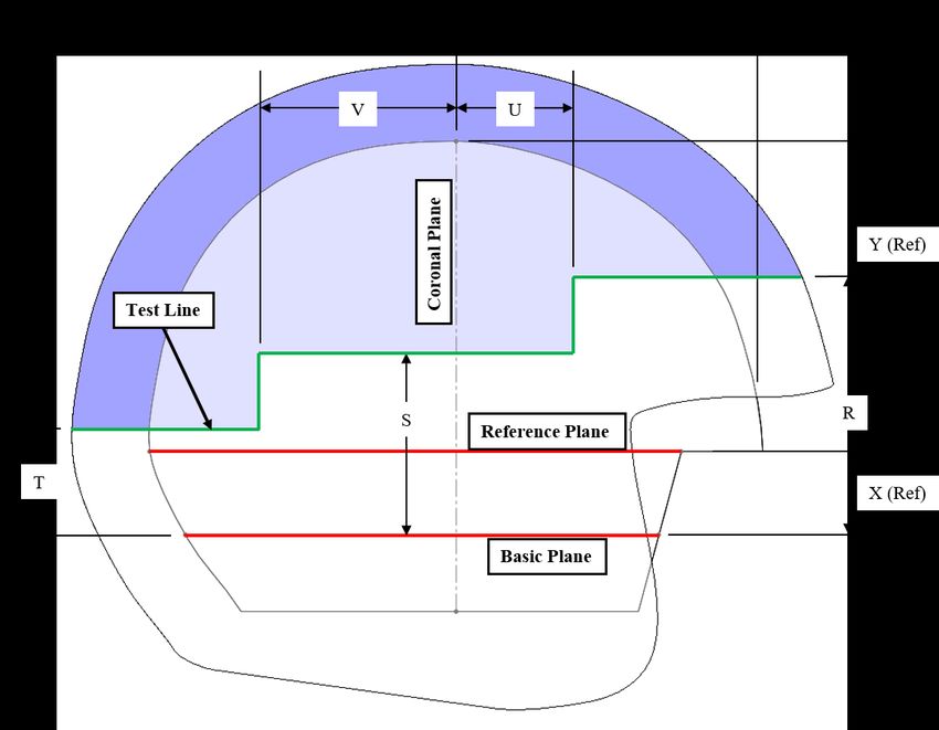
DOI/USFS Aviation Helmet Standard – Ver 4.0

FOREWARD

Developing the Civilian Aviation Helmet Standard
As with so many other aspects of aviation, the Office of Aviation Services (OAS) uses established industry
and government standards to guide our selection for safe and cost effective products that reduces risk to
injury. Occupational Safety and Health Administration (OSHA) and the American National Standards
Institute (ANSI) have established many standards that enable us to select equipment that will protect the
heads, eyes, and ears of employees. Hard hats, Safety Goggles, and hearing protection are easily identified
as a means of meeting an acceptable mitigation to various types of risk to personal injury.
In revising the Aviation Life Support Equipment (ALSE) Handbook (or ALSE Handbook), it was clear that
we needed to identify criteria that will provide an acceptable performance level for aviation helmets.
Adopting the military’s extensive institutional knowledge and expertise was once the only pragmatic option
until now as the marketplace of aviation helmets is much different from what it was a few years ago.
Problem: The civil aviation community is void of any guidance on aviation helmet standards.
Government regulatory agencies (such as OSHA) have not provided any guidance and the helmet
manufacturers have made no effort in establishing industry standards. An alternative that is used widely for
motorcycle helmets is DOT FMVSS 218, but fails to provide the desired parameters and performance
measures required for the aviation environment. Aviation helmets provide multiple levels of protection and
need to be evaluated for many properties including (but not limited to) crown and side impact, sound
attenuation, retention, and weight.
Although military approved helmets will remain authorized, simply adopting military specifications as our
own standard was eliminated as some of those specifications include areas that are not applicable to DOI.
Some of these areas include the Department of Defense (DoD) purchase process, design elements involving
ballistic protection, and packaging/delivery. Additionally, some military helmet models were built to an
American National Standards Institute (ANSI) standard (ANSI Z90.1) which is no longer supported by
ANSI. As such, these obsolete standards are unusable for ISO 9001 certified or ISO 17025 accredited
testing labs.
Solution: Acquire expertise that can develop modern, cost effective, proven performance standards
and testing methodologies.
OAS contracted with the Southwest Research Institute (SwRI), a well-regarded and recognized organization
with expertise in the area of helmet testing, on April 27, 2017 to provide technical, scientific systems
engineering and human factors subject matter expertise to develop modern, cost effective civilian aviation
helmet performance standards and testing methodologies.
Alternate Aviation Helmets
The DOI/USFS Aviation Helmets Standard Specification will provide an avenue to allow non-military
approved helmets to be considered for acquisition within our aviation communities. Both manufacturers
and distributors can test their helmets using an ISO certified laboratory to the DOI/USFS Aviation Helmet
Standards. Those meeting or exceeding these standards can be issued a certificate of compliance by the
laboratory. These helmets will be identified by the manufacturer and model type on the OAS website
(www.doi.gov/aviation/safety/helmet) within 30 days of receiving the certificate.

                                                     2
DOI/USFS Aviation Helmet Standard – Ver 4.0
0 RELEASE CONTROL RECORD
Table 0.1. Revision Table
Date Version Description Author
September 1, 2017 1.0 Initial release OAS
September 24, 2018 2.0 Editorial changes to all pages. Section 5.1, Page SwRI
11 – Modified bullet list to be consistent with
document. Section 5.1.1, Page 11, replaced “test
line” with “extent of coverage line”. Section
5.1.7, Page 15, modified bullet list of items to be
included in certificate to be consistent with
document. Section 6, Page 16, added Helmet E
to Table 6.1. Section 6.6, Pages 17 and 18,
Removed Test Line from Figure 6.1 and changed
text to identify that testing can be done to the
extent of coverage line. Section 6.10.1, Page 21,
Added Section 6.10.1 to require a system check
before and after impact testing. Deleted Section
6.10.2 Offset Distance to remove requirement
from document. Section 7, Page 24, Removed
section numbers TOC for report.
February 14, 2019 3.0 Changed Section 5.0 to clarify helmet sizes and SwRI
combinations to be tested.
Changed Section 6.0 to clarify the number of
helmets to be tested.
Changed Section 6.2 to define the test line and
provided a table with test lines for each ISO
headforms.
Changed 6.10.3 distance between all impact
locations shall not be less than one-seventh the
maximum circumference of the helmet.
February 26, 2019 4.0 Changed Figure 6.1 to reflect previous changes SwRI
to the Test line definition.
3DOI/USFS Aviation Helmet Standard – Ver 4.0
Table of Contents
Foreward ....................................................................................................................................................... 2
0 Release Control Record ........................................................................................................................ 3
1 Purpose.................................................................................................................................................. 6
2 Scope..................................................................................................................................................... 6
3 Referenced Documents ......................................................................................................................... 7
4 Definitions ............................................................................................................................................ 8
5 General Requirements for all Helmets ................................................................................................ 10
5.1 Configuration and Associated Inspections .................................................................................. 11
5.1.1 Helmet System .................................................................................................................... 11
5.1.2 Visor System ....................................................................................................................... 12
5.1.3 Retention System ................................................................................................................ 13
5.1.4 Ear Cup/Sound Attenuation System.................................................................................... 13
5.1.5 Communication Equipment ................................................................................................ 13
5.1.6 Instruction Manual .............................................................................................................. 14
5.1.7 Certifications ....................................................................................................................... 14
5.2 Labeling ...................................................................................................................................... 14
5.3 Vision .......................................................................................................................................... 15
5.4 Weight ......................................................................................................................................... 15
6 Testing ................................................................................................................................................ 16
6.1 Headform Selection .................................................................................................................... 16
6.2 Test Line ..................................................................................................................................... 17
6.3 Conditioning ............................................................................................................................... 18
6.4 Heat Exposure Testing ................................................................................................................ 19
6.5 Adhesion of Shell Edge Covering Testing .................................................................................. 19
6.6 Visor Testing............................................................................................................................... 19
6.7 Sound Attenuation Testing.......................................................................................................... 19
6.8 Communication Equipment Talk-Listen Testing ........................................................................ 20
6.9 Positional Stability Testing, Retention System ........................................................................... 20
6.10 Impact Attenuation Testing......................................................................................................... 21
6.10.1 System Check...................................................................................................................... 21
6.10.2 Anvils .................................................................................................................................. 21
6.10.3 Impact Locations ................................................................................................................. 21
6.10.4 Impacting Schedule ............................................................................................................. 22
6.10.5 Impact Velocities ................................................................................................................ 23
6.10.6 Peak Acceleration Requirements ........................................................................................ 23
6.11 Static Strength Testing, Retention System .................................................................................. 23
7 Report ................................................................................................................................................. 24
8 Keywords ............................................................................................................................................ 24
4DOI/USFS Aviation Helmet Standard – Ver 4.0
Blank Page
5DOI/USFS Aviation Helmet Standard – Ver 4.0
DOI/USFS Aviation Helmet
Standard
1 PURPOSE
The purpose of this document is to identify the minimum requirements and elements that should
be tested or evaluated to demonstrate that a given helmet conforms to the level of performance
required by the Department of the Interior (DOI) and the United States Forest Service (USFS) for
aviation use 1. Helmets are one of the key elements of a personal protective profile that personnel
conducting aviation operations can use to mitigate higher risk mission profiles. The helmet is an
effective means to prevent serious injury and death to pilots and crewmembers that may result
from aircraft mishaps.
2 SCOPE
This document specifies the minimum physical, functional, and performance requirements for both
helicopter and airplane (non-ejection seat) helmets for interagency use by pilots and crewmembers
conducting aviation activities. This specification is applicable for use by the Department of the
Interior and the United States Forest Service for aviation use. The tests and conditions specified
in this document are based on well established procedures within the industry and have a long
history within military helmet development. These currently include helicopter (SPH 2-5,
HGU 3-84 and HGU-56/P) and airplane (SPH-4B and HGU-55/E) helmets.
This specification is a performance standard and is not intended to restrict design. In addition, the
standard includes requirements specifically applicable to aviation helmets and requirements to
prevent helmets from coming off during an accident. The standard contains inspection, testing
and recordkeeping requirements to ensure that helmets meet the standard's requirements. The
standard establishes requirements derived from one or more of the military standards applicable to
helicopter and airplane helmets.
The intended audience for this document is the helmet manufacturers, distributors and third party
ISO 9001 certified or ISO 17025 accredited testing labs. This document provides the specific
inspection and qualification testing criteria. Helmets meeting the standards specified in this
document can be issued a certificate of conformity by a third-party accredited lab. Partial
utilization of this specification is prohibited. Any statement of compliance within this
specification shall be a certification that the product meets all of the requirements of the
specification in its entirety. A product that fails to meet any one of the requirements of this
specification is considered to have failed the standard and should not be sold with any indication
that it meets part(s) of the standard.
1
Acknowledgements: This standard is a commitment provided by a number of stakeholders from a number of
agencies, including Bureaus and Office within the Department of the Interior and the United States Forest Service.
2
Sound Protective Helmet (SPH)
3
Head Gear Unit (HGU)
6DOI/USFS Aviation Helmet Standard – Ver 4.0
3 REFERENCED DOCUMENTS
The following documents are referenced within this standard and are included as part of this
specification:
• ANSI/ASA S12.6–2016, Measurement of the Real-Ear Attenuation of Ear Protectors
at Threshold, American National Standards Institute, Inc.
• ANSI/ASA S12.42–2010, Methods for the Measurement of Insertion Loss of Hearing
Protection Devices in Continuous or Impulsive Noise Using Microphone-in-Real-Ear
or Acoustic Test Fixture Procedures, American National Standards Institute, Inc.
• ANSI/ASQ Z1.4–2008, Sampling Procedures and Tables for Inspection by Attributes.
• ASTM F1446-15b, Test Methods for Equipment and Procedures Used in Evaluating
the Performance Characteristics of Protective Headgear.
• ASTM F2220-15, Specification for Headforms.
• US DOT, Federal Motor Vehicle Safety Standard No. 218 FMVSS No. 218, 49 CFR
571.218, U.S. Department of Transportation, National Highway Traffic Safety
Administration.
• US DOT, TP–218-07, Laboratory, Test Procedure for FMVSS No. 218, Motorcycle
Helmets, U.S. Department of Transportation, National Highway Traffic Safety
Administration.
• MIL–DTL–27467B, Detail Specification, Headset, Electrical H-154A/AIC, 27 March
2015.
• MIL–DTL–43511D, Detail Specification, Visors, Flyer’s Helmet, Polycarbonate, 12
October 2006.
• MIL–DTL–87174A, Detail Specification, Helmet, Flyer’s HGU–55/P, Department of
the Air Force, 30 October 1998.
• MIL–H–27856D, Military Specification, Helmet, Flying HGU–7/P, Department of the
Air Force, 08 May 1981 (Canceled).
• MIL–H–43925D, Military Specification, Helmet, Flyer’s, Protective, SPH-4,
Department of the Army, 27 April 1988 (Inactive).
• MIL–PRF–27542F, Performance Specification, Microphone, and Microphone
Assemblies, Dynamic General Specification for, 18 May 2017.
• MIL–PRF–38169A, Performance Specification, Lens, Goggle and Visor, Helmet,
Optical Characteristics.
• MIL–STD–1916, DoD Preferred Methods for Acceptance of Product.
• USAARL Report No. 2012-14, Williams, Robert, Assessment of the Applicability of
ANSI S12.42-2010 as a General Measure of Protection from impulsive Nosie by
Measurement of Impulsive and Continuous Noise Insertion Loss of the HGU-56/P and
CEP, September 2012.
In the event of a conflict between the text of this specification and referenced standards, the text
of this document shall take precedence.
7DOI/USFS Aviation Helmet Standard – Ver 4.0
4 DEFINITIONS
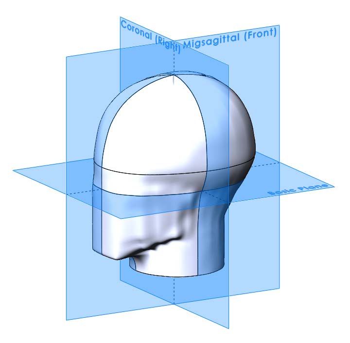
Basic Plane: An anatomical plane (Frankfort Horizontal Plane) that includes the superior rim of
the external auditory meatus (upper edge of the external opening of the ear) and inferior margin of
the orbit (the lowest point of the floor of the eye socket), Figure 4.1.
Chin Strap: The part of the retention system consisting of a strap that passes under the wearer’s
jaw to keep the helmet in position.
Comfort Padding: Material provided for the wearer’s comfort.
Coronal Plane: An anatomical plane perpendicular to both the basic and midsagittal planes and
passing through the superior rims of the right and left auditory meatuses, Figure 4.1.
Discrete Helmet Size: The size of the helmet that corresponds to standard industry convention
for measuring hat size. The American designation gives the diameter of an equivalent circle in
inches. The European designation gives the circumference of an equivalent circle in centimeters.
Ear Cup(s): The cup-like sections of a pair of headphones that enclose the user’s ears.
Easily Read Label: A label is considered easily read if the label is visible to the user without
removing any part and can be exposed, if necessary, so the user can read the required information.
Field of Vision: Peripheral angle and vertical opening of vision as measured on the reference
headform (upward, downward, and peripheral).
Headforms: Reference or test headforms that correspond to the physical dimension defined in
ASTM F2220 4.
Helmet (protective headgear): A protective device worn on the head in an effort to reduce or
minimize injury to that portion of the head that is within the areas of the test line.
Helmet Positioning Index (HPI): The vertical distance from the brow of the helmet to the basic
plane when the helmet is firmly and properly seated on a reference headform. For a given helmet,
the manufacturer shall specify the size of the headform and the HPI.
Liner: Material used to absorb impact energy.
Midsagittal Plane: An anatomical plane perpendicular to the basic plane and containing the
midpoint of the line connecting the notches of the right and left inferior orbital ridges and the
midpoint of the line connecting the superior rims of the right and left external auditory meatus,
Figure 4.1.
Permanent Label: A label is considered permanent if it cannot be removed without the aid of
tools or solvent, is attached by a seam, tears into at least three or more pieces when removed, or
damages the surface to which it was attached when removed.
Reference Plane: A plane marked on the headforms at a specified distance above and parallel to
the basic plane.
4
EN960:2006 Headforms may be used as an alternative. Note that there are differences between ASTM F2220 and
EN960:2006 geometries; these differences are such that the results will be comparable.
8DOI/USFS Aviation Helmet Standard – Ver 4.0
Retention System: The complete assembly that secures the helmet in a stable position on the
wearer’s head.
Shell: The hard part of the helmet which gives it its general shape.
Test Line: A line drawn on the helmet that identifies the area of the helmet subject to impact
testing. The helmet shall provide as uniform impact protection in this area as is practicable.
Visor: A transparent protective screen extending over the eyes and covering all or part of the face.
Figure 4.1. Anatomical Planes
9DOI/USFS Aviation Helmet Standard – Ver 4.0
5 GENERAL REQUIREMENTS FOR ALL HELMETS
These general requirements are associated with the helmets used by Department of the Interior and
the United States Forest Service for aviation, for use in both helicopters and airplanes.
The manufacturer/distributor is responsible for 5:
• Establishing their own manufacturing and process controls to produce helmets in
accordance with requirements.
• Performing or having performed all inspections and testing.
• Generating and maintaining sufficient evidence of conformance.
• Submitting helmets and supporting deliverables that conform to requirements.
• Using recognized corrective action and process improvement practices.
One or more of the following methods shall be used for verification that the helmets meet the
requirements of this standard:
• Inspection Verification without the use of special laboratory appliances or procedures.
May include visual examination, simple physical manipulation, and/or mechanical and
electrical gauging and measurement.
• Analysis Verification that utilizes established technical or mathematical models or
simulations, algorithms, charts, graphs, or other scientific principles and procedures.
• Demonstration Verification that involves actual operation, adjustment, or reconfiguration
of an item under specific scenarios. Items may be instrumented and quantitative limits of
performance measured.
• Test Verification that involves thorough exercising of an item under specified conditions
with instrumentation and data analysis accomplished in accordance with a set of applicable
test procedures.
Sampling for inspection and testing shall be performed in accordance with MIL-STD-1916 or
ANSI/ASQ Z1.4.
Testing is required on the supplied range of sizes for a given model of helmet. Table 5.1 gives the
range of sizes that accommodate 98% of the male and 98% of the female population with 90%
confidence of the remaining population being fitted with minor modifications to the existing sizes.
Testing shall be performed on each model combination of shell size and liner provided by the
manufacturer/distributor. Note that there may be differences in fit based on size for different
models of helmets.
Table 5.1. Typical Helmet Size Designation 6
Size of Helmet S M L XL XXL
Head size (cm) 54 – 55 56 – 57 58 – 59 60 – 61 62 – 63
Hat Size 6 3/4 – 6 7/8 7 – 7 1/8 7 1/4 – 7 3/8 7 1/2 – 7 5/8 7 3/4 – 7 7/8
5
Based on MIL-STD-1916.
6
Note that head and hat size measurement is more of an art than a science.
10DOI/USFS Aviation Helmet Standard – Ver 4.0
The following identifies the sequence for testing:
1. Inspection
a. Configuration and Associated Inspections, §5.1
b. Labeling, §5.2
c. Vision, §5.3
d. Weight, §5.4
2. Headform Selection, §0.
3. Test Line, §6.2
4. Conditioning, §6.3.
5. Testing shall be performed in the following order:
a. Heat Exposure Testing, §6.4
b. Adhesion of Shell Edge Covering Testing as necessary, §6.5
c. Visor Testing as necessary, §6.6
d. Sound Attenuation Testing as necessary, §6.7
e. Communication Equipment Talk-Listen Testing as necessary, §6.8
f. Retention System, Positional Stability Testing, §6.9
g. Impact Attenuation Testing, §6.10
h. Retention System, Static Strength Testing §6.11
5.1 Configuration and Associated Inspections
Helmets shall include the following components:
• Helmet System with Shell, Optional Edge Covering, Liner, and Comfort Padding
• Visor System
• Retention System
• Ear Cup and Sound Attenuation System
• Communication Equipment
Periodic inspection tasks for the helmets by the operator/user shall be sufficient to ensure they are
free from all defects which would affect proper functioning in service as identified in §5.1.1 to
§5.1.5. The periodic inspection intervals shall not be greater than one (1) year. The helmet shall
be examined from a distance of no greater than 0.6 meters.
5.1.1 Helmet System
The helmet shall include a shell, liner, and optional edge covering necessary to provide impact
protection, noise attenuation, and support for the retention system, visor(s), and communication
equipment. The optional edge covering is required if the edge of the shell where it may contact
the user is sharp 7. Each helmet shall have a protective surface (shell) of continuous contour at all
points on or above the test line 8. The helmet shall be inspected in accordance with Table 5.2 to
ensure that all components are present and free from all defects which would affect proper
functioning in service.
7
A sharp edge shall be defined as something likely to cut the skin if contacted.
8
Based on FMVSS No. 218 S5.4
11DOI/USFS Aviation Helmet Standard – Ver 4.0
Table 5.2. Helmet Inspection
Classification
Component Defect
Critical Major Minor
Visibly warped or distorted X
Cracked X
Scratched, scuffed, or abraded X
Shell
Mounting holes are damaged X
Unauthorized patching or repair X
Sharp edges X
Label Missing, illegible, or not of a permanent type X
Edge Covering Not properly secured to shell X
if Present Significant cracks, holes or tears X
Energy Liner not properly aligned in shell X
Absorbing Liner not uniformly bonded to shell X
Liner Gaps between liner and shell greater than 3mm X
Comfort Pads Significant holes, tears, or soiled areas X
5.1.2 Visor System
The helmet shall include one or two polycarbonate visors. The visor assembly shall provide for
the visor lens to remain in position when placed in either the fully deployed or fully stored position.
When deployed, the visor shall provide the wearer an unobstructed view of the aircraft
instrumentation while providing glare protection for the view outside the aircraft. The visor shall
be inspected in accordance with Table 5.3 to ensure that all components are present and it is free
from all defects which would affect proper functioning in service.
Table 5.3. Visor Inspection
Classification
Component Defect
Critical Major Minor
Visibly warped or distorted X
Significant cracks, scratched, scuffed, or abraded X
Visor Identification label missing or illegible X
Pile fastener not securely adhered to visor X
Sharp edges X
Edge Not properly secured to visor X
Covering if
present Significant cracks, holes or tears X
Buckle missing, webbing routed through buckles
X
incorrectly, or ends of webbing not seared
Attachment
Snap fastener and/or rivet components missing
X
or incorrectly set
Significant cracks, holes, or tears X
Lens Stop
Missing components X
12DOI/USFS Aviation Helmet Standard – Ver 4.0
5.1.3 Retention System
The helmet will have a retention system for positioning of the ear cups and securing the helmet to
the wearer. The retention system shall be inspected in accordance with Table 5.4 to ensure that all
components are present and free from all defects which would affect proper functioning in service.
Table 5.4. Retention System Inspection
Componen Classification
Defect
t Critical Major Minor
Grommet/rivet/snap fastener incorrectly installed or
X
damaged
Loose or damaged stitching, skipped stitches, or not
X
Chin Strap back–stitched
and/or Ends of webbing not seared X
Nape Strap Lacing cord not seared properly or improperly laced X
Fastener damaged or not functional X
Adjustment hardware damaged or not functional X
5.1.4 Ear Cup/Sound Attenuation System
The helmet shall have a system to provide sound attenuation to the wearer. The acoustic protection
system is typically made up of ear cups with headphones and soft ear pads for comfort. The ear
cups ensure correct acoustic protection and are fixed inside the helmet shell. The ear cup/sound
attenuation system shall be inspected in accordance with Table 5.5 to ensure that it is free from all
defects which would affect proper functioning in service.
Table 5.5.
Ear Cup/Sound Attenuation Inspection
Classification
Component Defect
Critical Major Minor
Ear Cup Improperly located in ear cup section X
Components Not secured properly to inside of helmet X
5.1.5 Communication Equipment
The communication equipment includes a headset and microphone assemblies. The
communication equipment shall be inspected in accordance with Table 5.6 to ensure that all
components are present and free from all defects which would affect proper functioning in service.
13DOI/USFS Aviation Helmet Standard – Ver 4.0
Table 5.6. Communication Equipment Inspection
Classification
Component Defect
Critical Major Minor
Visible damage that would cause malfunction X
Cable assembly damaged X
Microphone 9
Visible damage to the boom or attachment to
X
helmet
Visible damage that would cause malfunction X
Headset 10
Cable assembly damaged X
5.1.6 Instruction Manual
An instruction manual shall be furnished by the manufacturer/distributor with each helmet. This
manual shall provide operation and maintenance instructions for the helmet.
5.1.7 Certifications
The manufacturer shall furnish a document certifying that the helmet model and size was tested in
accordance with and meets this specification, and that the sample is tested is a true representation
of the helmet model purchased, to include construction, materials and components.
Upon successful completion of the testing in the standard, the test lab shall issue a certificate of
compliance to this standard. The certificate of compliance shall include:
• Applicant Name and Address
• Manufacturer Name and Address
• Product Description
o Helmet Information: Brand, Model, Manufacturer, Size, Type
(Helicopter/Airplane), and Manufacture Date
o Visor Information: Brand, Model, Manufacturer, Manufacture Date
o Ear Cup/Sound Attenuation Information: Brand, Model, Manufacturer,
Manufacture Date
o Communication Equipment Information: Brand, Model, Manufacturer,
Manufacture Date
• Test Information: Date of Test, Test Lab Project ID, Test Standard(s) Version and Date
• Compliance Statement: This document certifies that the item listed above was tested in
accordance with the requirements of DOI/USF Aviation Helmets Standard Specification,
and that the specific helmet model evaluated complied with all of the requirements.
• Test Lab Information: Name, Controlling Quality Program, Address
• Test Lab Certification Number, signature, and/or stamp
5.2 Labeling
Each helmet shall have a permanent type identification label applied to the helmet or liner that
includes: manufacturer, date of manufacture, model type, and discrete size similar to the
9
Reference MIL-PRF-26542F
10
Reference MIL-DTL-27467B
14DOI/USFS Aviation Helmet Standard – Ver 4.0
requirements in FMVSS No. 218 S5.6.1 11. The helmet shall be inspected to determine if the
required label is present, permanent, legible, easily read, and contains the required information.
5.3 Vision
The field of vision of the user shall not be significantly altered when wearing the helmet. With
the visor fully retracted, the helmet shall provide peripheral vision clearance of at least 105° to
each side of the mid-sagittal plane when the helmet is seated on the proper headform according to
the requirements of FMVSS No. 218 S5.4. The brow opening shall be at least 25 mm above all
points in the basic plane that are within the angles of peripheral vision according to the
requirements of FMVSS No. 218 S5.4.
5.4 Weight
The weight of the complete aviation helmet assembly ready for use including visors, sound
attenuation, and communication equipment shall not exceed that given in Table 5.7. Expected
maximum weight of a single visor system is 0.25 kg. Expected maximum weight of a dual visor
system is 0.35 kg. Expected maximum weight of the ear cups and communication equipment is
0.35 kg.
Table 5.7. Target and Maximum Helmet Assembly Weights
Size of Helmet S M L XL XXL
Head size (cm) 54 – 55 56 – 57 58 – 59 60 – 61 62 – 63
Target Weight (kg) 0.90 0.95 1.00 1.06 1.12
Maximum Weight (kg) 1.27 1.35 1.42 1.50 1.58
The weight of each helmet assembly shall be measured prior to the beginning of testing.
11
See also TP–218-07, Laboratory, Test Procedure for FMVSS No. 218, Motorcycle Helmets §12.5.4
15DOI/USFS Aviation Helmet Standard – Ver 4.0
6 TESTING
All helmets, including Type I Helicopter and Type II Airplane, shall be tested under the methods
and testing standards outlined within this Section. Helmet testing is required for each model of
helmet with respect to each combination of shell size and liner provided. Testing is required to be
performed on the smallest shell with corresponding thickest liner (smallest size), a medium or
large size (typically the most popular size), and the largest shell with the thinnest liner (largest
size). Visor, sound attenuation, and communication equipment testing is required only when those
components or their manufacturing process, including materials and/or suppliers, is changed.
A minimum of four (4) helmets in total are required for testing. Three (3) helmets, Helmets A, B
and C, are required for the impact and retention testing. A single (1) helmet, Helmet D, is required
for the heat exposure and adhesion of shell edge beading testing.
When sound attenuation and/or communications equipment talk-listen testing is required, an
additional (1) helmet, Helmet E, is required for each variation of communication system provided
in the helmet model. For example, testing standard speaker and noise cancellation communication
systems would require two helmets for Helmet E and would not require a new set of helmets for
impact, retention, and heat exposure testing.
When visor testing is required, three (3) visor lenses for each variation of optical density (i.e. -
clear, tinted, etc.) in the helmet model are required for the distortion and transmissivity testing.
Table 6.1 provides a break-down of which test items are required for each test sequence.
Table 6.1. Test Sequence
Helmet
Test Visor*
A B C D E*
6.1 Headform Selection X
6.2 Test Line X
6.3 Conditioning Ambient Low High
6.4 Heat Exposure Testing X
6.5 Adhesion of Shell Edge
X
Covering
6.6 Visor X++
+
6.7 Sound Attenuation X
6.8 Communication Equipment
X+
Talk-Listen
6.9 Positional Stability X
6.10 Impact Attenuation X X X
6.11 Static Strength Testing,
X X X
Retention System
* When required.
+
Requires one (1) additional helmet for each variation of communication system offered in the helmet model to be
tested.
++
Requires three (3) visor lenses for each variation of visor optical density offered in the helmet model to be tested.
6.1 Headform Selection
The helmets shall be tested on the appropriate headform size based on the discrete size and fit on
the headform. The headforms used for this testing will be ISO headforms in accordance with the
16DOI/USFS Aviation Helmet Standard – Ver 4.0
requirements of ASTM F2220 and ASTM F1446. Variable mass headforms will be used as
reflected in Table 6.2.
Table 6.2. Test Headform Mass and Size Specifications
Headform Drop Assembly Size Designation Nominal Helmet
Size Mass (cm) Size (cm)
A 3.1 ± 0.10 kg 49.5 50
C 3.6 ± 0.10 kg 51.5 52
E 4.1 ± 0.12 kg 53.5 54
J 4.7 ± 0.14 kg 57.5 57
M 5.6 ± 0.16 kg 60.5 60
O 6.1 ± 0.18 kg 62.5 62
The determination of which headform is appropriate to use with a specific helmet is based on the
specified smallest and largest head circumferences for the helmet, Table 5.1, in relation to the
headform size, Table 6.2. The smallest and largest head circumferences will be taken directly from
the helmet label or obtained from the manufacturer/distributor. The headform to use during testing
is the largest of the headforms whose circumference is no greater than the manufacturer’s specified
largest circumference. If the helmet does not fit the largest headform, the next smaller headform
should be selected. If it is determined that the helmets are too small even for the smallest
appropriate headform as indicated by the manufacturer’s discrete size specification, the samples
shall be rejected for testing.
During testing, helmets will be positioned on the selected test headform according to the
manufacturer’s specified helmet positioning indices. If the manufacturer fails to provide
positioning information with the certification samples, the helmets will be positioned according to
the best judgment of experienced test personnel.
6.2 Test Line
The test line, Figure 6.1, shall be marked on the helmet (Helmet A) in accordance with the
procedures identified in FMVSS No 218. To mark the test line, the helmet shall be placed on the
headform in the position that conforms to the helmet positioning index (HPI) supplied by the
manufacture/distributor. Each helmet shall have a protective surface of continuous contour at all
points on or above the test line. The center of impacts can be positioned such that they are on or
above the test line.
17DOI/USFS Aviation Helmet Standard – Ver 4.0
Headform
X L/2 Y R S T U V
Size
A 24.0 88.0 89.7 78.5 56.5 34.5 32.0 58.5
C 25.0 91.5 93.0 80.5 57.5 34.5 33.5 60.0
E 26.0 94.5 96.0 82.5 58.5 34.5 35.5 62.0
J 27.5 101.0 102.5 85.5 60.0 34.5 38.5 65.0
M 29.0 106.0 107.0 88.0 61.5 34.5 40.0 66.5
O 30.0 108.5 110.0 89.5 62.5 34.5 42.0 68.5
Dimensions in mm
Figure 6.1. Test Line
6.3 Conditioning
Conditioning of the helmets prior to testing shall be in accordance with FMVSS No. 218,
paragraph S6.4 with the following exceptions.
• Ambient Temperature: 21°C ± 5°C (Helmet A)
• Ambient Relative Humidity: 50%RH ± 20%
• Low Temperature: -10°C ± 5°C (Helmet B)
18DOI/USFS Aviation Helmet Standard – Ver 4.0
• High Temperature: 50°C ± 5°C (Helmet C)
Low and high temperature conditioning shall be for a minimum duration of four hours and no more
than twenty-four hours prior to testing. Note that the water immersed conditioning requirements
of FMVSS No. 218 are not included in this specification.
6.4 Heat Exposure Testing
The helmet shall satisfy the performance requirements of §3.4.2 of MIL-DTL-847474A, excluding
the measurement between reference dimples. The helmet assembly (Helmet D) shall be at ambient
test conditions for at least one (1) hour prior to testing. The helmet assembly shall then be weighed
and then shall be placed on its crown in an air–circulating oven at a temperature of 70°C ± 5°C for
a 4–hour (± 15 minutes) period. The helmet assembly shall then be removed from the oven and
conditioned at ambient test conditions for 1 hour (± 15 minutes). The helmet assembly shall then
be weighed, and any change in weight following the exposure shall not exceed 1% of the original
weight. Following the heat exposure test, there shall be no distortion of helmet components,
defects in finish, or separation of adhesive bonds that would impair performance of the helmet.
6.5 Adhesion of Shell Edge Covering Testing
The helmet shall satisfy the performance requirements of §3.5.2 and §3.5.3 of MIL-H-43925D
using acceptance requirements identified below. The helmet assembly (Helmet D) shall be at
ambient test conditions for at least 1 hour prior to the initial check of adhesion. The same helmet
shall then be aged on its crown in an air–circulating oven at 70°C ± 5°C for a period of four to
twenty-four hours. The helmet assembly shall then be removed from the oven and conditioned at
ambient test conditions for 1 hour (± 15 minutes), followed by the final adhesion check shall be
performed.
Prior to and after aging of the helmet, the edge covering shall remain bonded to the shell. The
beading shall be considered un-bonded when the edge can be rolled back on itself and away from
the shell by applying force with the ball of the thumb. Up to a total length of 50mm of un-bonded
length is acceptable if:
• No individual un-bonded length is more than 15mm
• There is at least 10mm between any two un-bonded lengths
The bonding shall be checked at a minimum of three locations on the helmet shell: front, side and
rear.
6.6 Visor Testing
Visors shall be installed on the helmets for all testing where they do not interfere with the
performance of the test. Visor testing for optical characteristics is required only during initial
certification and when the related components or their manufacturing process, including materials
and/or suppliers, are changed. The visors shall be polycarbonate and shall meet the distortion
requirements defined by MIL-PRF-38169 §3.3.4 as well as the clear and neutral density visors
transmissivity requirements defined by MIL-DTL-43511D §3.5.3. Distortion and transmissivity
testing shall be performed on three visors. Any test failure shall be cause for rejection of the lot.
6.7 Sound Attenuation Testing
Sound attenuation components shall be installed on the helmets for all testing where it does not
interfere with the performance of the test. Sound attenuation testing to establish noise attenuation
19DOI/USFS Aviation Helmet Standard – Ver 4.0
values is required only during initial certification and when the related components or their
manufacturing process, including materials and/or suppliers, are changed. Sound attenuation for
the helmet (Helmet E) shall be determined in accordance with ANSI/ASA S12.6 or ANSI/ASA
S12.42. Historically, ANSI/ASA S12.6 testing has been used and includes real-ear attenuation at
threshold (REAT) methods for the measurement of the noise attenuation of hearing protection
devices using test subjects. REAT procedures are considered the best way to measure the amount
of protection that a sound attenuation system provides 12. ANSI/ASA S12.42 includes acoustic test
fixture test procedures for measurement of insertion loss of hearing protection devices. If
ANSI/ASA S12.42 insertion loss is used in lieu of ANSI/ASA S12.6, a correction factor for bone
conduction, occlusion effects, and physiological masking must be included.
The sound attenuation feature shall provide sufficient attenuation such that exposure does not
exceed 100% of the Acoustic Dose. Total daily exposure is defined as 85 dBA for 8 hours. To
accomplish this, the target helmet noise attenuation target values given in Table 6.3 are used. Any
test failure shall be cause for rejection of the lot.
Table 6.3. Helmet Noise Attenuation Targets
Hertz 125 250 500 1000 2000 3150 4000 6300 8000
Decibels 17 14 20 21 26 38 37 46 42
6.8 Communication Equipment Talk-Listen Testing
Communication equipment testing is required during initial certification or only when the
components or their manufacturing process, including materials and/or suppliers, are changed.
The system shall be compatible with or replace current communications devices designed for use
with aircrew helmets. The system shall be compatible with or include a boom microphone.
Communication equipment testing shall be performed in accordance with MIL-DTL-27467B
§3.5.2.1 and §3.5.2.2. Helmet E assembly shall be tested by connecting the headset assembly,
including a microphone, to a suitable test system. The testing will be a simple talk-listen test.
When the microphone is spoken into, there must be side tone in each earphone of the headset.
There shall be no buzzes, rattles, or voice distortion during testing. Any test failure shall be cause
for rejection of the lot.
6.9 Positional Stability Testing, Retention System
The retention system of the ambient helmet (Helmet A) shall be subjected to the positional stability
(roll-off) test in accordance with ASTM F1446 §7.2.2 using a 4 kg drop mass from a height of 0.6
m. The headform shall comply with the dimensions of the full chin reference headforms of ASTM
F2220. The headform size shall be the same as that used for impact attenuation testing. Testing
of the helmet in the face-up and face-down configurations shall be performed. The retention
system shall remain intact, the helmet shall remain on the headform and displacement shall not be
excessive. Excessive displacement is observed when those parts of the coronal plane that were
covered by the helmet before the test become exposed after testing in either orientation. Any test
failure shall be cause for rejection of the lot.
12
USAARL Report No 2012-14
20DOI/USFS Aviation Helmet Standard – Ver 4.0
6.10 Impact Attenuation Testing
The ambient (Helmet A), cold temperature (Helmet B), and high temperature (Helmet C) helmets
shall be impact tested in accordance with FMVSS No. 218, Paragraph S5.1 with the following
deviations and modifications:
• The helmet shall be fitted to the appropriate sized variable mass ISO headform. (See Table
6.2)
• For all impacts, the helmet assembly shall be fully assembled, less mic/boom assembly,
and positioned in the "as worn" condition with the outer visor lowered as far as possible.
• Only single impacts will be conducted at each location.
6.10.1 System Check
Pre-test and post-test system check drops will be performed as part of the impact series for each
set of helmets under test to identify possible faults in the system in accordance with the
requirements of US DOT, TP–218-07. The series of check drops will be made using only the test
headform and drop assembly. The headform shall be bare and the point of impact near the crown
with the accelerometer axis vertically aligned. During the post-test, the headform shall be aligned
in a manner that is consistent with the pre-test check drop.
The drop height and standardized impact media (a 2.54 cm open blue Modular Elastomer
Programmer (MEP) Calibration Pad has proven suitable for this purpose) for these checks shall be
chosen to demonstrate the system's capability to produce and record an acceleration vs. time
history of (nominally) 400 g with a minimum 1 msec duration above 200 g.
A systems check shall consist of 6 drops. The first 3 drops are considered "warm-up" drops.
Permanent recording of data is not required for these impacts. The acceleration time histories for
the second 3 drops shall be recorded and the results of these drops shall become part of the test
data presented in the final report. In addition, immediately prior to the first pre-test system check
drop, an accurate (± 0.1% voltage) calibration signal shall be injected into the system. The output
produced by this signal shall be recorded and retained on file.
If either of the following conditions exists, the impact system check shall be considered invalid.
A system level root cause shall be identified and fixed prior to additional testing:
(1) None of the three pre-test or post-test recorded accelerations are greater than 375 g, or
(2) The average of pre-test and post-test checks (recorded drops only) differs by more than
15 g.
6.10.2 Anvils
Anvils to be used for impact tests in this specification are described as follows:
• Flat Anvil, as described in FMVSS No. 218 S7.1.10.
• Hemispherical Anvil, as described in FMVSS No. 218 S7.1.10.
6.10.3 Impact Locations
As identified in TP-218-07 S12.6.2, the centers of impacts on the shell of the helmet can be
anywhere on or above the test line. The impact locations shall be the same for the three
environmentally conditioned helmets (Helmets A, B and C). The distance between all impact
locations shall not be less than one-seventh the maximum circumference of the helmet at the test
21DOI/USFS Aviation Helmet Standard – Ver 4.0
line. Any impact which hits the visor rail assemblies shall be considered invalid and subject to
retest. Impacts on other parts of the visor assembly are acceptable.
6.10.3.1 Type I Helicopter Helmets
Each helmet tested shall be impacted with a single impact at each of seven impact sites; front, rear,
left and right sides, crown, and left and right ear cups. The headform orientations given in Table
6.4 satisfy these impact location requirements and are consistent with historical military flight
helmet locations.
The impact locations at the "center" of each ear cup are with the coronal plane of the headform
vertically and the basic plane oriented such that the line of impact is perpendicular to the helmet
shell 13. The ear cups shall be fitted with an equal number of fitting pads on each side. The number
of fitting pads shall be such that a uniform and approximately 50 percent compression of the ear
seal results on each side to simulate the as-worn condition.
Table 6.4. Impact Locations for Type I Helicopter Helmets
Location Basic Plane from Vertical Rotation about Z-Axis 14 Anvil
Front 35° ± 10° ± 35° Flat or Hemi
Rear 15° ± 10° ± 35° Flat or Hemi
Sides 20° ± 10° ± 35° Flat or Hemi
Crown 90° ± 35° ± 180° Flat or Hemi
Ear Cups 5° ± 10° ± 10° Flat
6.10.3.2 Type II Airplane Helmets
Each helmet tested shall be impacted with a single impact at each of five impact sites: front, rear,
left and right sides, and crown. The headform orientations given in Table 6.5 satisfy these impact
location requirements.
Table 6.5. Impact Locations for Type II Aircraft Helmets
Location Basic Plane from Vertical Rotation about Z-Axis 15 Anvil
Front 35° ± 10° ± 35° Flat or Hemi
Rear 15° ± 10° ± 35° Flat or Hemi
Sides 20° ± 10° ± 35° Flat or Hemi
Crown 90° ± 35° ± 180° Flat or Hemi
6.10.4 Impacting Schedule
The type of anvil used at each of the impact sites are given in Table 6.4 and Table 6.5. The impact
sites and associated anvils can be performed in any sequence.
For Type I Helicopter Helmets two or three of the shell impact sites shall use the flat anvil, and
the remaining shell impact sites shall use the hemispherical anvil. The ear cup sites will use the
flat anvil.
For Type II Airplane Helmets, two or three of the shell impact sites shall use the flat anvil, and the
remaining shell impact sites shall use the hemispherical anvil.
13
Note that the modified Medium FMVSS No. 218 headform with extended sides is not required for this testing.
14
Z-Axis if the intersection of the coronal and midsagittal planes.
15
Z-Axis if the intersection of the coronal and midsagittal planes.
22DOI/USFS Aviation Helmet Standard – Ver 4.0
6.10.5 Impact Velocities
Impact velocity measurements and requirements are in accordance with FMVSS No. 218 S5.1
with the following exceptions:
• The helmet shall be dropped onto the flat anvil from a height sufficient to produce an
impact velocity (terminal velocity) of 6.0 ± 0.2 meters per second.
• The helmet shall be dropped onto the hemispherical anvil from a height sufficient to
produce an impact velocity (terminal velocity) of 5.2 ± 0.2 meters per second.
• The impact velocity shall be measured during the last 40 mm of free-fall for each test.
6.10.6 Peak Acceleration Requirements
The acceleration time histories and peak acceleration (g max ) during each impact shall be measured
with equipment described in FMVSS No. 218. The peak acceleration of any impact on the shell
of the helmet shall not exceed 300 g. The peak acceleration of any impact on the ear cup of the
helmet shall not exceed 190 g, and the average acceleration of ear cup impacts shall not exceed
175 g.
6.11 Static Strength Testing, Retention System
The retention system of the helmets conditioned at ambient (Helmet A), cold temperature (Helmet
B), and high temperature (Helmet C) conditions shall be subjected to the static strength retention
system requirements of FMVSS No. 218 S7.2 with the following exceptions:
• The headforms shall be the ISO headforms of ASTM F2220.
The headform size shall be the same as that used for impact attenuation testing. The helmet shall
be mounted in a system identified in FMVSS No. 218 that provides an adjustable load mechanism
with simulated chin, a means for holding the test headform and helmet stationary, and a system to
measure chin strap extension. The helmet is placed on the headform in accordance with the HPI
identified by the manufacturer/distributor. The retention system is fastened to the simulated jaw,
and preload of 22.7 kg is applied and held for 30 seconds. The load is then gradually increased to
136 kg and held for not less than 2 minutes. There shall be no separation of components at 136 kg
of applied force. Chinstrap elongation shall be no greater than 32mm between the 22.7 kg preload
and 136 kg load conditions. Any test failure shall be cause for rejection of the lot.
23DOI/USFS Aviation Helmet Standard – Ver 4.0
7 REPORT
The final report and associated documentation are relied upon as the chronicle of the helmet testing
performed and must be capable of standing by itself. The final report shall describe in detail any test events
that deviate from this document. The report and Table of Contents shall include at least the following:
Purpose of Helmet Testing
Helmet Testing Data Summary
Configuration and Associated Inspections
Labeling
Vision
Weight
Headform Selection
Test Line
Conditioning
Heat Exposure Testing
Adhesion of Shell Edge Covering Testing
Visor Testing (if applicable)
Sound Attenuation Testing (if applicable)
Communication Equipment Talk Listen Testing (if applicable)
Positional Stability Testing, Retention System
Impact Attenuation Testing
Static Strength Testing, Retention System
Test Failure Details (if applicable)
Appendix A —Interpretations or Deviations from this Standard
Appendix B —Test Equipment List and Calibration Information
8 KEYWORDS
Helmet, protective headgear, aviation, helicopter, airplane
24You can also read