I.T. Cooling Close Control Computer Room Air Conditioning Systems - les.mitsubishielectric.co.uk - ASP Events
←
→
Page content transcription
If your browser does not render page correctly, please read the page content below

I.T. Cooling
Close Control Computer Room
Air Conditioning Systems

                              les.mitsubishielectric.co.uk
Page 2

A new generation of
I.T. Cooling technology

We are all becoming more and       It is imperative that these vital I.T. servers and equipment are
                                   always kept in optimal conditions, with effective cooling being
more reliant on technology.        paramount. The new range of Computer Room Air Conditioning

Most businesses depend on
                                   (CRAC) systems from Mitsubishi Electric combine the latest in
                                   DX Technology with the RC brand’s expertise in I.T. cooling.
their I.T. systems to provide      These innovative, energy efficient systems can effectively
                                   deliver robust solutions to I.T. environments with ease.
the data they need, 24/7, year     DX Computer Room Air Conditioning solutions from
after year, as even the shortest   Mitsubishi Electric offer a range of high sensible systems,
outages can cause significant       specifically designed to provide close control of temperature
                                   and humidity; perfectly suited for small to medium sized
disruption and loss of revenue.    enterprise data centres.

                                   Mitsubishi Electric purchased the RC Group in 2015,
                                   enhancing our product line up and marking our full scale
                                   entry into the I.T. cooling market.
Page 3

RC is a strong European brand supported by 50 years                 Through our technical expertise, long experience and
of customer trust and high quality production, and its              innovative product range, we enable building operators
range of energy-saving, low-noise and innovative                    everywhere to significantly improve energy efficiency,
I.T. cooling technology further expands our                         reduce running costs and adhere to increasingly tough
application and customisation capabilities.                         legislation. We believe that global climate challenges
                                                                    need local solutions.

Mitsubishi Electric is the first                                     Our aim is to help individuals and businesses reduce
name for comfort and efficiency                                      the energy consumption of their buildings and their
                                                                    running costs.
Founded in 1921, Mitsubishi Electric is now a global, market
leading environmental technologies manufacturer. In the UK,              At Mitsubishi Electric, we offer
the Living Environment Systems Division provides pioneering
solutions that heat, cool, ventilate and control our buildings in        advanced technology that really
some of the most energy efficient ways possible.                         can make a world of difference.
Page 4

The need for
I.T. Cooling

Precise temperature and
humidity control
More and more businesses are opting to store their data          Because of the need for close control 24 hours a day,
on-site in enterprise data centres, and in the past standard     365 days a year, an inverter driven compressor has been
wall mounted split systems may have been an option to            incorporated into many of the outdoor units, maximising
cool this type of application.                                   the energy efficiency of each system. Features include:

However, complex I.T. environments are often characterised          DX or chilled water versions
by variable cooling loads, which require a high cooling
                                                                    Precise temperature and humidity control
capacity at full load in order to allow the I.T. equipment
to operate correctly when it is most needed.                        High Sensible cooling
                                                                    Easily integrates into existing and new control networks
The perfect match between                                           Back-up and rotate functions
efficiency and reliability                                           Inverter driven capacity control
The need for high sensible cooling and close control of             New generation EC PUL (Polymeric Ultralight)
both temperatures and humidity in critical I.T. environments        high efficiency fans
has therefore never been higher, and this is where our new          Free cooling
range of specialist I.T. cooling systems makes it possible
to keep temperature and humidity constant, even with                Dual fluid circuits available for the highest reliability
very wide load variations, ensuring the correct room
conditions all year round.

With our I.T. cooling systems, both efficiency and reliability   Designing the optimum
are paramount throughout all the stages of research,
design and manufacturing. By using this approach, along          I.T. cooling system
with over 50 years of manufacturing experience within            Two factors need to be taken into account when designing
the I.T. cooling sector, we are able to offer tailor made        the perfect system for I.T. cooling: density and capacity.
I.T. cooling solutions that have been designed to fulfil         Mitsubishi Electric's wide range of products allows you
this requirement, reducing operational costs in the              to choose the correct balance of these factors, in order
process through the use of highly efficient technology.          to meet your individual application requirements.

                                                                 Mitsubishi Electric’s range of dedicated I.T. cooling
Mitsubishi Electric close                                        equipment includes DX systems specifically designed
control cooling systems                                          for I.T. applications, and for those who are familiar with
                                                                 the benefits and installation processes of our existing
Mitsubishi Electric’s close control systems are specifically     Mitsubishi Electric HVAC outdoor units. This opens up
designed for rooms with a high sensible cooling load that        new opportunities for the application of DX systems
require precise temperature and humidity control.                in critical I.T. environments.

Page 6

Density - Low / Medium / High

When considering the type of air conditioning required for an I.T. cooling
application, one of the most important factors to consider is density.

What does density mean?
The density of an I.T. cooling application describes how much cooling power is required to remove the heat
produced by the I.T. equipment or machinery in a given space.
For most I.T. cooling applications, the ‘space’ is a computer rack, which
is a physical chassis that can house multiple computers, or servers.
A computer rack is also known as a server rack or computer cabinet.

To characterise the density, the cooling power required to maintain the
temperature in the rack must be calculated.

For I.T. cooling applications where the cooling power required in a single
rack is less than 5kW, this would be described as low density.

Where the cooling power required is between 5-15kW, the density of                  Low Density       Med Density         High Density
                                                                                    15kW/Rack
the rack would be described as being medium, and where greater
than 15kW, described as high.

Selecting the right system
In low density applications it is possible to maintain temperatures in the rack by controlling the room
temperature as a whole, using perimeter air conditioners.
However, as the density of the rack increases, the risk of localised areas of the data room overheating also increases,
and these ‘hot spots’ must be removed to ensure I.T. equipment isn’t damaged through overheating.

To remove the risk of hot spots in higher density
applications, localised cooling is installed
closer to the racks to ensure the cooling
is delivered where it’s needed most.
Page 7

Low Density Applications

Computer room air conditioners, known
as CRAC units, are located around the
perimeter of the data room.

These systems draw warm air in from
the racks, while cooler conditioned air
is then typically blown under a raised
floor and out through grilles to the front
of the server racks, to create hot and
cold aisles within the data room.

Medium Density Applications

Perimeter CRAC units (as described above) are combined with aisle containment
for medium density applications. In this type of system, the cold and hot air streams
are physically separated to ensure they do not mix, and to prevent
hot spots from occurring.

32.2ºC
                                     15.8ºC

26.7ºC
                                    10ºC

21.1ºC

High Density Applications

For the highest density applications, the addition of localised cooling can meet the heavy demands of the system. In-row,
in-rack or rear door coolers are used to bring the conditioned air right up to the server inlet, ensuring the servers within the
rack are maintained at optimum temperature. This is commonly referred to as close coupled air conditioning.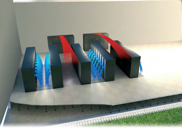
Page 8

Capacity - Small to Large Scale Applications

Another factor that will dictate the
type of equipment required for an                                 The Gap in Capacity
I.T. cooling application is the total                    As system capacity increases, it becomes
capacity of the data centre.                             impractical to install a large number of
                                                         small wall mounted systems. However,
                                                         at the same time the application doesn’t
 Small Capacity Applications                             lend itself to apply highly specialised
                                                         I.T. cooling equipment.
 Smaller capacity applications are commonly              This is where the s-MEXT DX comes in; it uses
 designed with more cost effective and simpler           the same ethos of ‘plug and play’ as our Mr Slim
 direct expansion (DX) technology. DX equipment          split-system technology, and helps fill the gap
 doesn’t require the installation of water pipework      between low and high capacity applications,
 or the need of 3rd party ancillaries, such as           without any upskilling requirement.
 pumps and control valves, making them a
 convenient solution for smaller projects.
 Historically, contractors may have chosen to install
 comfort cooling air conditioning products in these
 types of applications. While these products offer a
 solution, a more targeted approach is often required,
 and as such we have developed the M Series MSY-TP
 wall mounted system, which has been designed
 specifically for high sensible cooling.

                         MSY-TP                                             s-MEXT DX

                   5kW - Small                                         50kW - Medium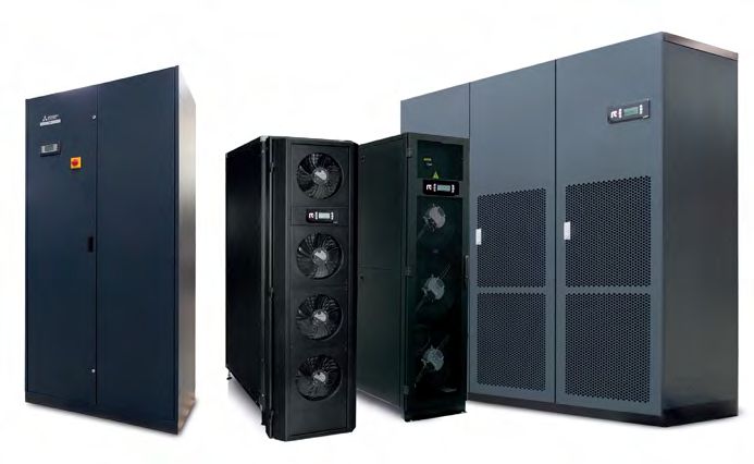
Page 9

Large Capacity Applications
For large capacity applications customers and installation contractors would usually opt for
highly specialised applied products. Applying these products requires a high level of design
and product knowledge.
Usually these products are bespoke and are typically installed by specialist
I.T. cooling contractors.

DX technology is utilised in this arena, however in these larger applications,
technology that uses chilled water becomes more prevalent. These systems,
while being higher in terms of CAPEX, can offer increased efficiency
through the use of free cooling and higher operating
temperatures in the data centre, where running
costs are more important to manage.

                                                   i-NEXT
                                                       s-MEXT
                                                          DX / w-NEXT
                                                               DX

     i-NEXT
         s-MEXT
            DX / w-NEXT
                 DX

   100kW - Medium                                  200kW - Large                 400kW - Large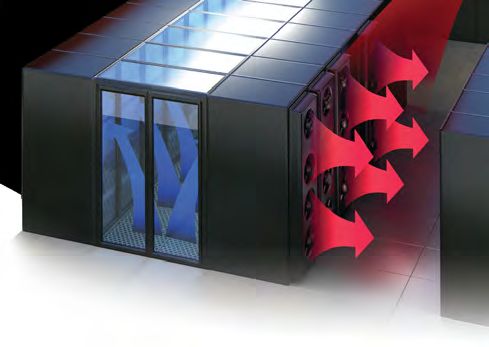
Page 10

Low Density / Low Capacity Applications

The need for high sensible cooling
Dedicated I.T. cooling equipment provides many benefits for small, low density I.T. cooling applications.
Although comfort cooling systems can be convenient solutions, specific I.T Cooling systems are strongly
recommended where there is a need for high sensible cooling.
The total cooling capacity of any air conditioning unit is comprised of "sensible cooling" and "latent cooling".

    Sensible cooling is the ability to remove heat that causes a change in temperature, but no change in the moisture content
    Latent cooling is the ability to remove moisture from the surrounding environment

The cooling capacity stated for a comfort cooling air conditioning unit is usually its total cooling capacity (i.e. sensible + latent).
Latent cooling is important in comfort cooling applications due to the presence of people in the space, who will produce moisture
in the air and increase the humidity levels.

However, in a data centre, the electronic equipment generates only dry heat (no moisture), so the sensible cooling capacity
becomes the most useful value. The common way to define this is to use the sensible heat ratio (or sensible heat factor) which
is expressed as:

                                            (Sensible Cooling)
 Sensible Heat Factor (SHF) =
                                            (Total Cooling)

For comfort air conditioning, the SHF is typically between 0.60 and 0.70; the coil/airflow is designed to remove 60% to 70%
sensible heat load and 30% to 40% latent heat load (moisture). The cooling equipment used in a data centre is designed for an
SHF between 0.85 and 0.95; that is 85% to 95% sensible heat load and 5% to 15% latent load. These cooling units will effectively
remove the high sensible heat load produced by the electronic equipment in a data centre.
Page 11
M Series MSY-TP R32 High SHF Wall Mounted System
The M Series MSY-TP wall mounted system blends energy efficiency with a modern white design.
This cooling only unit has a high sensible cooling capacity, making it ideal for low density / low capacity computer rooms or
areas that require a greater degree of sensible cooling.
High sensible cooling capacity
Cooling down to -25ºC outdoor air temperature
Highly energy efficient
Weekly timer for greater control of scheduling
Utilises lower GWP R32 refrigerant
The MSY-TP unit has a high SHF alongside a high Seasonal Energy Efficiency Ratio (SEER), which when combined, leads to a lower
running cost over the course of its lifetime. The MSY-TP is able to achieve a higher SHF through using an oversized evaporator,
which is designed for a high DELTA T across the coil.
When compared to a standard comfort cooling air conditioner,
the MSY-TP unit offers significant run cost savings over its lifetime.
Run Cost Comparison of Mitsubishi Electric Wall Mounted Systems - 15 Years
35,000
3x
MSZ-HR35VF
30,000 (Comfort)
1x
PKA-M100KA
25,000 (Comfort)
20,000
Cost (£)
15,000
10,000 3x
MSY-TP35VF
(High SHF)
5,000
0
0 1 2 3 4 5 6 7 8 9 10 11 12 13 14 15
YearsPage 12
Filling the Gap:
Medium Density / Medium Capacity Applications
Introducing the s-MEXT DX Close Control System
Computer room air conditioning is ideal for applications where high sensible cooling and close control of
temperature and humidity are required.
s-MEXT takes advantage of more than 50 years experience of the RC brand within the I.T. cooling market, coupled with
Mitsubishi Electric renowned quality standards.
The split cooling package consists of the indoor s-MEXT high precision air conditioner connected to a Mr Slim Power Inverter
outdoor unit. The result is a full inverter split system, designed according to the best quality standards and dedicated to the
most reliable I.T. environments.
Hybrid of packaged and bespoke equipment High efficiency
Plug and play technology with up to 100m pipe runs Full Mitsubishi Electric inverter technology and EC plug fans
Reliable and trusted technology 3 years warranty on the indoor unit
Compact with small footprint Up to 7 years warranty on the outdoor unit
6-42kW in either upflow or downflow configurations
s-MEXT DX CRAC Units Mr Slim Power Inverter Outdoor UnitsPage 13
Trusted Mitsubishi Electric Power Inverter technology
The s-MEXT DX system is able to be connected to either our new lower GWP R32 refrigerant Power Inverter
outdoor units, or its R410A version. The use of a Power Inverter outdoor unit simplifies the installation
process, removing the need for oil traps and double risers and allowing pipe sizes to be easily calculated.
Developed for high-performance operation, the Power Inverter offers a host of advanced functions:
Redundancy functions with automatic switchover in the event of a fault
‘Easy maintenance’ function and automatic refrigerant level monitoring
Inverter Compressor allows for continuous modulation, achieving a high energy saving performance
Inverter DC Axial fans
New generation EC fans
High performing EC fans on the s-MEXT unit are made of polymeric ultralight material in order to ensure perfect airflow modulation
at partial loads. The fans deliver advantages in terms of:
Reduction of noise levels by 4-5 dB(A) compared to traditional solutions
Reduction of the absorbed power by 25% compared to traditional solutionsPage 14
s-MEXT DX Close Control System
Harnessing the highest capacity into a compact footprint
s-MEXT controls temperature and relative humidity with pinpoint accuracy, even in
the case of very strong thermal variations. Brilliantly engineered to deliver top-class
efficiency values, the indoor unit features a range of premium quality components,
such as EC plug fans, an evaporating coil with hydrofilic treatment and a
PID microprocessor control system.
A wide selection of accessories are also available
to suit the most critical installation requirements.
The fact that the compressor is contained Optimal
in the outdoor unit allows for a compact Ratio
s-MEXT footprint when compared to kW/m2
standard CRAC units, freeing up
valuable space in the data centre.
Extended pipe runs and lift
30m
By combining the s-MEXT CRAC unit with the Lift
Mr Slim Power Inverter outdoor unit, pipe runs
of up to 100m with a 30m lift (height difference)
are possible.Page 15
Airflow options
The s-MEXT is available in two different airflow configurations, ensuring installation flexibility.
Downflow (under) Upflow (over)
With bottom air supply and top return With top air supply and frontal air return
Warranty
3
years warranty
on the s-MEXT
indoor unit
up to
years warranty
on the Mr Slim Power
Inverter outdoor unitPage 16
Medium Density / Large Capacity Applications
i-NEXT DX / w-NEXT Close Control Systems
High precision air conditioners are ideal for applications where high sensible cooling and close control of
temperature and humidity are required. Both the i-NEXT DX and w-NEXT ranges make it possible to keep
temperature and humidity constant even with very strong load variations, ensuring premium sensible
cooling capacity values.
Perimeter units with upflow and downflow configurations
Ultralight composite EC plug fans resulting in reduced noise and power usage
Integrated control of up to 10 units for intelligent redundancy management
Automatic restart from power outage
Return air temperature operating limits up to 40°C
Optional Modbus RS485 and BACnet TCP/IP connectivity
Optional electrical heater and steam humidifiers
The i-NEXT direct expansion air cooled range is perfect for keeping room conditions constant under varying loads, whilst being
highly energy efficient.
The w-NEXT is a high precision air conditioner designed for I.T. cooling that utilises a chilled water feed.
i-NEXT DX 10-129kW w-NEXT 6-204kWPage 17
Precise temperature and humidity control
Complex I.T. environments are characterised by extremely variable thermal loads, which require a high level
of cooling capacity at full load, to ensure the continual efficient and effective operation of I.T. equipment.
The i-NEXT DX and w-NEXT provide this, ensuring a reliable performance throughout the lifetime of the system.
Airflow configurations
Like with the s-MEXT DX, both the i-NEXT DX and the w-NEXT systems are available in both downflow and upflow configurations,
ensuring installation flexibility across a multitude of applications.
Downflow (under) Upflow (over)
Air suction is from the top of the unit and air Air intake can be at the front, rear or bottom of the
delivery is provided to the underfloor void. unit, and the air delivery is from the top of the unit,
into ducts behind suspended ceilings or from front
delivery plenums.
EC plug fans
Specifically designed for high precision air conditioners, the new EC PUL (Polymeric ULtralight)
fans of the i-NEXT DX and w-NEXT feature a new compact design and an innovative blade
geometry, resulting in a higher airflow rate and reduced operating costs. The advantages
compared to standard EC fans are:
Reduction in noise levels by 4-5dB(A)
20% efficiency increasePage 18
i-NEXT DX Close Control System
The i-NEXT DX air cooled range incorporates full inverter driven BLDC Mitsubishi Electric compressors and
a new microchannel coil remote condenser, perfect for keeping room conditions constant under varying
loads, whilst being highly energy efficient.
The best of both worlds:
The i-NEXT is available in both DX only, as well as a Dual Fluid version for maximum resilience, alongside the ability to incorporate
free cooling from ambient heat rejection plant.
Full inverter technology with BLDC Mitsubishi Electric compressors
Microchannel coil remote condensers with AC axial fans
Front access for easy inspection and routine maintenance
i-NEXT DX Configurations
DX Only Dual Fluid
Remote Condenser
Chiller
Remote Condenser
i-NEXT DX i-NEXT DX
GR-Z Microchannel Coil Remote Condensers
The GR-Z models are high efficiency remote condensers that can
be coupled with the i-NEXT DX close control air conditioning units.
Each condenser features microchannel coils and AC axial fans in order to provide the
best-in-class efficiency and higher corrosion resistance. The condensers can be
installed either vertically or horizontally and are available as an ultra-low noise version.
Key Features
50% less refrigerant charge compared to traditional finned coil remote condensers, with up to a 45% increase in
heat exchange efficiency
Microchannel condenser coil consisting of parallel flow aluminium tubes, result in a greater level of heat exchange
due to a lower thermal resistance, weight reduction and a lower pressure level
Stable and efficient operation is achieved thanks to the use of uncoated aluminium blades, dynamic balancing
and precise airflow control
AC Fans include optimised full bell mouth with guiding vane and short diffuser
Low noise levels are achieved due to the incorporation of AC fans, advanced electronics
and sound-proof insulation
High corrosion resistance on both the aluminium casing and coilsPage 19
w-NEXT Chilled Water Close Control System
Ideal for applications where high sensible cooling and close control of temperature and humidity are
required. The w-NEXT chilled water range incorporates the latest EC plug fan(s), advanced controls
software and an increased coil area resulting in the highest efficiency.
High Efficiency - EC plug fans
Small footprint
Adaptive Set Point
Active Redundancy
Available in Upflow (over) and Downflow (under) variants
High water temperatures
Integrated temperature control
w-NEXT Configurations
Single Circuit Double Circuit
Single chilled water circuit configuration
Chilled water air conditioners utilise water coming from a single chiller as a means to transfer heat. The liquid flow in the unit’s water coil
is managed by an internal 2 or 3-way valve.
Double chilled water circuit configuration
These units are provided as standard with two water circuits that never work simultaneously, as they operate as 100% back up to
each other. Such circuits are connected to two different chiller lines, completely independent of one another.
Dual circuit configurations are the perfect solution for applications where Reliability, Safety and Redundancy are paramount.Page 20
High Density Applications
In I.T. cooling applications where the cooling required per rack exceeds 15kW,
the risk of hot spots demand a more targeted cooling solution.
Mitsubishi Electric’s range of close coupled air conditioning solutions
Utilising the latest generation of cooling technologies to prevent the risk of hot spots in the data centre, the goal of close
coupled air conditioning is to bring the cooling technology as near to the heat source as possible: the computer rack.
By moving the air conditioner closer to the computer rack, a more precise delivery of inlet air and a more immediate capture
of exhaust air is possible, ensuring the most demanding I.T. systems are kept at optimal conditions, reducing the risk of
outages, while maintaining optimal efficiency.
Multi Density City Multi
VRF System - 50kWPage 21
Multi Density with Variable Refrigerant Flow [VRF]
Bringing together Mitsubishi Electric’s leading VRF Technology with
close coupled precision cooling.
Mitsubishi Electric’s new Multi Density systems combine the efficiency, quality and simplicity of City Multi VRF, with high performance
close coupled cooling solutions for high density data rooms.
Plug and play Long pipe runs
High efficiency Proven technology
Mitsubishi Electric cooling only VRF outdoor units
Multi Density is ideal for applications where high sensible cooling and close control
of temperature in high density applications is required. Multi Density takes advantage
of more than 50 years’ experience of the RC brand within the I.T. cooling market,
coupled with Mitsubishi Electric renowned quality standards.
This indoor cooling package consists of multiple Coolside close coupled
air conditioners, connected to a City Multi VRF outdoor unit. The result is
a full inverter multi-split system, designed according to the best quality
standards and dedicated to the most reliable I.T. environments.
Wide operating range
Self-developed inverter compressor technology
M-Net control
Mitsubishi Electric Quality, manufactured in Japan
Coolside close coupled In-row cooling solutions
These systems are suitable for application in modern I.T. infrastructure that is typically
characterised by high thermal loads, and are particularly suitable for high density racks
and blade server cooling in data centres with hot-spots.
The range is able to cope with the high density of the thermal load, with minimal impact
of space in the data centre. In-row technology puts the air conditioning unit directly
within the rows of racks to cool the localised heat sources.Page 22
Multi Density Features & Benefits
Up to 8 close coupled indoor units connected to one VRF outdoor unit
High density hot spots are cooled by multiple indoor units connected to a VRF outdoor unit,
working together as a unique system.
Compact footprint
By minimising the number of outdoor units, the overall footprint of the system is reduced.
System reliability
Multi Density is configurable to provide customers with
their desired level of reliability (configuration N, N+1, 2N).
The Multi Density system is in line with TIER III and IV
design topologies, based on the configuration selected.
Application flexibility
Match any kind of cooling requirement, from localised cooling, to hot and cold aisle cooling management.
Plug and play installation
No additional elements such as pumps, tanks or valves are required. This helps to reduce
installation time and costs, and minimise future maintenance requirements.
Active redundancy
The Active Redundancy function ensures that heat loads are balanced amongst the units (including those
units in stand-by) according to the actual system requirements of the I.T. infrastructure. Multi Density is
perfectly set-up for this, due to its multi unit configuration.Page 23
The modular approach of Multi Density Systems
Close coupled In-row units are connected in a primary-secondary configuration. If the primary unit becomes disconnected,
‘Dynamic Primary’ logic automatically elects a new primary from the remaining units and the system will continue to operate effectively.
Thanks to the flexible and modular approach of the Multi Density system, selection of the ideal solution for a data centre, based on
the level of redundancy required, is easily achievable.
Configuration without redundancy (N)
Ideal for small to medium sized I.T. applications
1 outdoor unit paired with up to 5 indoor units
Average system EER is approx. 3.00
Cooling capacity up to 50kW
Configuration with redundancy (N+1)
Ideal for TIER II I.T. applications
2 outdoor units paired with up to
8 indoor units
The external units operate load sharing
at partial loads for higher efficiency
In case of failure of one of the outdoor
units, the second one operates at full load
Average system EER approx. 3.25
Cooling capacity up to 50kW
Configuration 2N
Ideal for TIER III and TIER IV data centres
In accordance with the Uptime Institute’s
classification, this configuration offers:
A fully redundant and mirrored system
with two independent distribution systems
1+1 outdoor units paired with
5+5 indoor unitsPage 24
High Density Coolside Legacy Range
The Coolside range of close coupled air conditioning systems provides
highly efficient targeted cooling, low operating costs and a flexible layout.
Modulation of airflow is possible due to the incorporation of EC high efficiency fans:
EC fans adapt to the thermal load detected by sensors positioned in the hot and cold aisles
New generation EC brushless fans made of ultralight material
Noise level reduction of 4-5 dB(A) compared to standard fans
Absorbed power reduction of 15% compared to standard fans
‘Hot Swappable’ EC fans can be accessed from the front
Active free cooling
High density Coolside Legacy solutions (single or dual circuit) allow a water circuit to harness the free cooling potential. In the
Coolside Dual Circuit version, while the primary circuit (circuit 1) could be water cooled via an external dry cooler in order to
maximize the free cooling benefits, the secondary backup circuit (circuit 2) can be easily combined with a free cooling chiller,
for perfect redundancy and unbeatable efficiency.
Direct expansion or chilled water versions available
Perfectly compatible with most racks and ready for future expansion of the cooling system.
Coolside DX: Direct Expansion
DC inverter compressor
New generation EC brushless fans
Capacity from 4.7 to 68.3kW
Coolside CW: Chilled Water
New generation EC brushless fans
3-way modulating valve
Capacity from 16 to 74.7kW
Coolside DF: Dual Fluid Coolside FC: Free Cooling
DC inverter compressor DC inverter compressor
Double coil New-generation EC brushless fans
Capacity from 4.5 to 16.7kW Capacity from 4.6 to 17.5kW
60% of the year in free cooling
Coolside Row DX: Direct Expansion with Integrated Compressor
Installation within the row; does not require underfloor plenum, ducts or false-ceilings
DC inverter compressor integrated within the air conditioner
Capacity from 14 to 39kWPage 25
Coolside Legacy Configurations
From large to small I.T. environments, Coolside Legacy solutions are available in both ‘In-row’ and ‘Enclosure’ configurations,
providing a range of adaptable data centre solutions.
In-row air delivery options
Ideal for hot and cold aisles, the ‘In-row’ configuration draws the air from the hot aisle of the data centre (35°C) through the
rear of the unit. The air is then cooled and delivered to the cold aisle (18-20°C) from the front of the rack.
Left-side frontal air delivery. Frontal air delivery from Right-side frontal air delivery. Frontal air delivery.
Rear air suction. both sides. Rear air suction. Rear air suction. Rear air suction.
Enclosure
Ideal for removing hot spots in stand-alone systems, the ‘Enclosure’ configuration is where both
the servers and the air conditioners are coupled on the same structure, avoiding the mixing of
air streams and creating a clean environment within the rack. The air is directly treated inside
the rack; entering at 46°C, cooled down to 25-30°C and then delivered back to the servers.
This increases energy saving thanks to the low quantities of treated air.
Right-side frontal air delivery. Left-side frontal air delivery. Frontal air delivery from both sides.
Right-side air suction from the rear. Left-side air suction from the rear. Rear air suction from both sides.Page 26
Coolside Door System
The Coolside Door unit is an innovative and efficient system
for managing hot spots inside data centres, where very
high density racks are present.
The Coolside Door unit is housed at the rear of the rack and is managed by a dynamic system,
especially designed to handle the rack exhaust air, while intelligent controls adapt to the
rack requirements.
The Coolside Door unit can be considered both as a stand-alone cooling unit for the exhaust air
of a single rack in small data centres, or as a system for managing hot spots in large data
centres to support the function of hot and cold aisles or aisle containment structures.
Chilled water coils available in both single and double circuits
Zero footprint
Adaptable for almost all racks
High energy efficiency with electronically controlled
fans modulated to specific needs
Dynamic air stratification management of the rack temperatures
thanks to eight independent sensors
Flexible connections from the top and from the bottom, depending on
choice and on raised floor availability 32-36ºC 40-50ºC 20-25ºCPage 28
Free Cooling Technology - the ultimate solution
to harness the full potential of outdoor air
In British climates, data centre managers can reduce the OPEX (operating expenditure) of their I.T. cooling
plant by taking advantage of favourable environmental conditions, when the outdoor air is cooler than the
operating water temperature serving the air conditioning units.
For example, in a data centre with an operating water temperature of 28/20°C (In/Out), a free cooling chiller from RC can satisfy the
whole cooling demand for 50% of the time utilising free cooling. For the majority of the remainder of the time, the demand is then
satisfied by running the compressors at part loads, alongside free cooling. This means that 99.9% of the time the chiller will be
operating with free cooling activated, and will spend minimal time in pure ‘mechanical’ mode.
Free Cooling Hybrid Mechanical
500
400
Hours (h)
300
200
100
Free-cooling for 99.9% of the time
0 0
-20 -15 -10 -5 0 5 10 15 20 25 30 35
Outdoor temperature (ºC) 11ºC 27ºC
The higher the water operating temperature - the greater the annual free cooling potential
The energy saving as a result of the use of free cooling is dependent on the water temperature required to operate the air conditioning
units within the data centre. Raising the operating water temperature, allows the use of free cooling for larger proportions of the year.
Comparing the efficiency of a free cooling chiller and a traditional scroll compressor chiller, the large efficiency gap in the free cooling
temperature range is evident. In any modern I.T. infrastructure, free cooling technology is a crucial technology to reduce
OPEX and energy usage.
In total free cooling, the compressors are off and minimum energy is needed to satisfy
the nominal cooling capacity
Energy Efficiency Comparison
Free Cooling Chiller (NR-FC-Z) Chiller with scroll compressors
150
EER = 120
125
100
EER
50
25
EER = 7 EER = 4
0
-20 -10 0 10 20 30 40
Outdoor temperature (ºC) Note: Operating water temperature 28ºC/20ºC (in/out).Page 29
NR-FC-Z
Free Cooling Chiller dedicated to
high temperature I.T. environments
Air cooled chiller with scroll compressors and free cooling technology from 364 to 978kW
Specifically designed to operate with high water temperatures (supply set-point up to 24°C) and
a high DELTA T (up to 11°C), the NR-FC-Z delivers substantial energy savings in modern data
centres. The free cooling hydraulic equipment allows the unit to utilise outside air to meet the
cooling capacity.
When the air temperature is too high to allow complete free cooling, highly efficient scroll compressors ensure
full load coverage. Smart LAN functions also allow simple plug and play connection of multiple NR-FC-Z chillers
and enhance the system’s efficiency and stability.
Smart LAN Logic
Embedded functions for multi-unit systems
Group controls
Up to 16 chillers can be connected and run as a group to enhance the system’s efficiency and dependability.
Dynamic primary Resource priority management
Stand-by unit management Group fast restart
Load sharing or sequencing Centralised pump control
Adaptive set-point
The indoor chilled water units communicate their load conditions to the external group of chillers, adjusting their operating set-point
accordingly, maximising energy savings.
Total Free Cooling from 11ºC
Thanks to large free cooling coils, the NR-FC-Z uses the outdoor air as its main source to produce cooling. With a set-point of
20°C, the total free cooling operation is possible from outdoor air temperatures of 11°C. This means that most of the time
the chiller can provide the required cooling capacity without using the compressor.
The highest standards of reliability and reduced running costs,
without any compromises.Page 30
i-FR-G05-Z
Air Cooled Inverter Chiller
Air cooled chiller with inverter screw compressors for outdoor installation from 477 to 1697kW
Thanks to the variable speed technology applied on both the compressors and fans, the i-FR-G05-Z
ensures top-level energy efficiency values and complete dependability.
Optimised to work with high temperature I.T. environments, the chiller’s outstanding performance brings significant
PUE (Power Usage Effectiveness) reduction and helps to keep the OPEX under control.
r
R513A LOW GDP Non-flammable
-56% GWP vs R134a Safety Class A1
Leading Inverter Technology High Degree of Configurability
The new i-FR-G05-Z showcases the latest variable A bespoke list of options, such as integrated hydronic modules,
speed technology: allows the i-FR-G05-Z to be configurable for multiple applications.
Dual screw compressors with integrated refrigerant
cooled inverter motor and smart variable Vi Logic Extended Operating Range
High efficiency variable speed fans Wide operating range, working with outdoor air temperatures
from -20°C up to +55°C, thanks to specifically developed
Optional variable speed hydronic modules options and smart control logic.
Smart Variable Vi Logic
Variable speed drive
Pressure
An integrated and compact frequency converter (refrigerant cooled) Zero Under / Over
for outstanding seasonal efficiency and wide capacity regulation. Compression
Energy Waste
Automatic internal volume ratio adaption Discharge Pressure
=
Condenser Pressure
An integrated Vi slider adapts the internal geometry to the current
operating condition, thus ensuring the best efficiency.
Variable Vi
Extra durability achieved via dedicated components: Evap.
Envelope control function, 3-stage warning and alarm system, Pressure
Volume
safe-torque-off function
Carbon steel bearings granted for a lifetime of over 150,000 hours
High efficiency high speed motor
For unprecedented full and part load efficiencies and extremely wide
and accurate capacity regulation.
Twin Screw Compressor with Integrated Vi SliderPage 31
TRCS-FC-G05-Z
High Efficiency Air Cooled
Free Cooling Chiller
High efficiency air cooled chiller with oil-free compressors and free cooling from 302-1693kW
Strict energy consumption and environmental impact Key Features
regulations continually drive for more efficient
Oil Free magnetic levitating centrifugal compressors
air conditioning. Achieving the greatest energy savings
and ensuring long-term sustainability are challenges Inverter driven compressor
that modern cooling systems need to address. EC Fans
r Wide use of free cooling
R513A LOW GDP Non-flammable
-56% GWP vs R134a Safety Class A1 Highest level of efficiency
The TRCS-FC-Z range of chillers adopts highly efficient oil-free centrifugal technology with an advanced free cooling system that
has been conceived to reduce the compressor operation and maximise the use of the outdoor air.
This leading compressor technology brings benefits in terms of efficiency, adjustments, vibrations and weight. Magnetic levitation
eliminates the need for lubricant, through precise management of the levitating drive shaft. Partial load efficiency, which is crucial
during the hybrid operation, is therefore dramatically increased.
This product utilises the RC brand’s knowledge and experience in oil-free compressor unit development, across multiple of
projects all over the world.Specifications
Page 33

MSY-TP
High SHF Wall Mounted System - Inverter Heat Pump (Cooling Only)

The M Series MSY-TP High SHF wall mounted system blends energy efficiency with a modern white design.
This cooling only unit has a high sensible cooling capacity, making it ideal for small computer rooms or areas that require a greater
degree of sensible cooling. The MSY-TP also utilises lower GWP R32 refrigerant.

Key Features
    Compact and stylish white design
    High sensible cooling ability
    Weekly timer provides greater control of scheduling
    Cooling down to -25ºC outdoor air temperature

 MSY-TP - INDOOR UNITS
MODEL                                                                                  MSY-TP35VF               MSY-TP50VF
CAPACITY (kW)                           Cooling (nominal)                                3.5 (1.5-4.0)            5.0 (1.5-5.7)
                                        Cooling (UK)                                   3.47 (1.48-3.96)         4.96 (1.48-5.65)
SHF (nominal)                                                                                0.98                     0.82
EER (nominal)                                                                                4.61                     3.45
SEER (BS EN14825)                                                                            9.00                     8.00
ErP ENERGY EFFICIENCY CLASS             Cooling                                              A+++                      A++
AIRFLOW (l/s)                           Cooling - Lo-Mi-Hi-SHi                        168-193-228-273          168-193-228-273
PIPE SIZE mm (in)                       Gas                                               9.52 (3/8”)              9.52 (3/8”)
                                        Liquid                                            6.35 (1/4”)              6.35 (1/4”)
SOUND PRESSURE LEVEL (dBA)              Cooling - Lo-Mi-Hi-SHi                           31-36-40-45              31-36-40-45
SOUND POWER LEVEL (dBA)                                                                       60                       60
DIMENSIONS (mm)                 Width x Depth x Height                                 923 x 250 x 305          923 x 250 x 305
WEIGHT (kg)                                                                                  12.5                     12.5
ELECTRICAL SUPPLY                                                                      220-240v, 50Hz           220-240v, 50Hz
FUSE RATING (BS88) – HRC (A)                                                                  10                        10
INTERCONNECTING CABLE No. CORES                                                                4                         4

 MUY-TP - OUTDOOR UNITS
MODEL                                                                                  MUY-TP35VF               MUY-TP50VF
SOUND PRESSURE LEVEL (dBA)              Cooling                                               45                       47
SOUND POWER LEVEL (dBA)                 Cooling                                               58                       61
WEIGHT (kg)                                                                                   34                       34
DIMENSIONS (mm)                         Width x Depth x Height                         800 x 285 x 550          800 x 285 x 550
ELECTRICAL SUPPLY                                                                     Fed by Indoor Unit       Fed by Indoor Unit
PHASE                                                                                       Single                   Single
SYSTEM POWER INPUT (kW)                 Cooling (nominal)                                    0.76                     1.45
                                        Cooling (UK)                                         0.64                     1.12
STARTING CURRENT (A)                                                                          3.6                      6.4
SYSTEM RUNNING CURRENT (A)         Cooling [MAX]                                           3.6 [9.2]                6.4 [9.2]
FUSE RATING (BS88) – HRC (A)                                                                  10                       10
MAINS CABLE No. CORES                                                                          3                        3
MAX Pipe LENGTH (m)                                                                           20                       20
MAX HEIGHT DIFFERENCE (m)                                                                     12                       12
CHARGE REFRIGERANT (kg) / CO2 EQUIVALENT (t) - R32 (GWP 675)                             0.85 / 0.57              0.85 / 0.57
MAX ADDITIONAL REFRIGERANT (kg) / CO2 EQUIVALENT (t) - R32 (GWP 675)                     0.13 / 0.09              0.13 / 0.09

Notes: The SHF figures are based on nominal conditions.
Requires an additional MAC-334IF-E interface and PAR-40MAA wired remote controller.
Page 34
s-MEXT-G00 DX
R32 Close Control System
Computer room air conditioning is ideal for applications Key Features
where high sensible cooling and close control of High Efficiency - full Mitsubishi Electric
temperature and humidity are required. inverter technology and EC plug fans
Small footprint
s-MEXT takes advantage of more than 50 years experience of the RC brand
within the I.T. cooling market, coupled with Mitsubishi Electric renowned quality Trusted Mr Slim Power Inverter technology
standards. The split cooling package consists of the indoor s-MEXT Pipe runs up to 100m
air conditioner connected to a Mr Slim R32 Power Inverter outdoor unit.
The result is a full inverter split system, designed according to the best Available in Upflow [over] and
quality standards and dedicated to the most reliable I.T. environments. Downflow [under] variants
CRAC UNITS (Computer Room Air Conditioning)
s-MEXT-G00 DX s-MEXT-G00 DX s-MEXT-G00 DX s-MEXT-G00 DX s-MEXT-G00 DX s-MEXT-G00 DX
MODEL 006 S F1 009 S F1 013 S F1 022 S F2 038 D F3 044 D F3
COOLING CAPACITY (kW)*1 Total 6.82 10.1 11.9 22.6 39.0 42.5
Sensible 6.18 8.91 10.2 19.3 33.6 35.3
SHR*2 0.91 0.88 0.86 0.85 0.86 0.83
SYSTEM EER 4.67 4.30 3.49 3.18 3.58 2.88
EC SUPPLY FAN (no.) 1 1 1 2 1 1
AIRFLOW (m³/h) 2,000 2,500 2,800 5,000 8,800 10,000
NOMINAL EXTERNAL STATIC PRESSURE (Pa) 20 20 20 20 20 20
MAX EXTERNAL STATIC PRESSURE (Pa) 208 22 110 21 129 20
POWER INPUT (kW)*3 0.21 0.35 0.47 0.70 1.43 1.96
REFRIGERANT R32 R32 R32 R32 R32 R32
REFRIGERANT CIRCUITS (no.) 1 1 1 1 2 2
AIR FILTERS No. 1 1 1 2 4 4
Extended filtering surface (m²) 0.68 0.68 0.68 1.05 1.76 1.76
Efficiency [ISO EN 16890] (COARSE) 60% 60% 60% 60% 60% 60%
SOUND LEVEL [ISO 3744] (dB(A))*4 Pressure Level 53 57 61 60 63 67
Power Level 69 73 77 76 79 83
POWER SUPPLY (V/Ph/Hz) 230 / 1 / 50 230 / 1 / 50 230 / 1 / 50 230 / 1 / 50 400 / 3 / 50+N 400 / 3 / 50+N
ABSORBED CURRENT (A)*3 1.5 2.1 2.7 3.0 2.1 2.8
STARTING CURRENT (A) 2.0 2.0 2.8 3.3 3.8 3.8
MAX ABSORBED CURRENT (A) 2.3 2.3 2.8 3.9 3.8 3.8
ELECTRICAL PANEL Power Input (kW) 0.14 0.14 0.14 0.14 0.14 0.14
DIMENSIONS (mm) Width 600 600 600 1000 1000 1000
Depth 500 500 500 500 890 890
Height 1980 1980 1980 1980 1980 1980
NET WEIGHT (kg) Upflow 103 106 110 165 237 237
Downflow 110 115 120 175 247 247
CONNECTIONS Refrigerant pipes diameter - Gas (Ø Inch) 5/8" 5/8" 5/8" 1" 1" 1"
Refrigerant pipes diameter - Liquid (Ø Inch) 3/8" 3/8" 3/8" 1/2" 3/8" 1/2"
Condensate (Ømm)*5 19 19 19 19 19 19
Power Supply wiring Cable (no. x mm²)*6 3G1.5 3G1.5 3G1.5 3G1.5 5G1.5 5G1.5
OUTDOOR UNITS
MODEL PUZ-ZM60VHA PUZ-ZM100VKAR1 PUZ-ZM125YKAR2 PUZ-ZM250YKA 2 x PUZ-ZM200YKA 2 x PUZ-ZM250YKA
SOUND PRESSURE LEVEL (dB(A)) Cooling 47 49 50 59 59 59
WEIGHT (kg) 70 116 125 138 137 138
DIMENSIONS (mm) Width x Depth x Height 950 x 330 + 25 x 943 1050 x 330 + 40 x 1338 1050 x 330 + 40 x 1338 1050 x 330+40 x 1338 1050 x 330+40 x 1338 1050 x 330+40 x 1338
ELECTRICAL SUPPLY 220-240v, 50Hz 220-240v, 50Hz 380-415v, 50Hz 380-415v, 50Hz 380-415v, 50Hz 380-415v, 50Hz
PHASE Single Single Three Three Three Three
OUTDOOR POWER INPUT (kW) Cooling (nominal) 1.25 2.00 2.94 6.41 4.73 6.41
STARTING CURRENT (A) 5.0 5.0 5.0 5.0 5.0 5.0
MAX RUNNING CURRENT (A) Cooling 19.2 27.0 10.0 22.5 22.5 22.5
FUSE RATING (BS88) - HRC (A) 25 32 16 32 32 32
MAINS CABLE No. Cores 3 3 5 5 5 5
MAX PIPE LENGTH (m) 55 100 100 100 100 100
MAX HEIGHT DIFFERENCE (m) 30 30 30 30 30 30
CHARGE REFRIGERANT (kg) / CO2 EQUIVALENT (t) R32 (GWP 675) - 30m 2.80 / 1.89 4.00 / 2.70 4.00 / 2.70 6.80 / 4.59 6.30 / 4.25 6.80 / 4.59
MAX ADDITIONAL REFRIGERANT (kg) / CO2 EQUIVALENT (t) R32 (GWP 675) 0.80 / 0.54 2.80 / 1.89 2.80 / 1.89 2.40 / 1.62 (70m)*7 1.60 / 1.08 (70m)*7 2.40 / 1.62 (70m)*7
GUARANTEED OPERATING RANGE (°C) Max Temp 46 46 46 46 46 46
Min Temp*8 -15 -15 -15 -15 -15 -15
Notes: The cooling capacity does not consider the supply fan motor thermal load. *1 Gross value based on return air of 27ºC - 47%RH; Ambient Temperature 35ºC; ESP=20PA; Interconnecting pipework length 5m.
*2 SHR = Sensible cooling capacity / Total cooling capacity. *3 Corresponding to the nominal ESP=20Pa. *4 Sound pressure level on air return at 1m. *5 Rubber pipe - referred to internal diameter. *6 Minimum section.
*7 For 70 to 100m please consult the service handbook. *8 Optional air protection guide is required for temperatures below -5°C. These units contain fluorinated greenhouse gas.Page 35
s-MEXT-G00 DX
R410A Close Control System
Computer room air conditioning is ideal for applications Key Features
where high sensible cooling and close control of High Efficiency - full Mitsubishi Electric
temperature and humidity are required. inverter technology and EC plug fans
Small footprint
s-MEXT takes advantage of more than 50 years experience of the RC brand
within the I.T. cooling market, coupled with Mitsubishi Electric renowned Trusted Mr Slim Power Inverter technology
quality standards. The split cooling package consists of the indoor s-MEXT
Pipe runs up to 100m
air conditioner connected to a Mr Slim R410A Power Inverter outdoor unit.
The result is a full inverter split system, designed according to the best Available in Upflow [over] and
quality standards and dedicated to the most reliable I.T. environments. Downflow [under] variants
CRAC UNITS (Computer Room Air Conditioning)
s-MEXT-G00 DX s-MEXT-G00 DX s-MEXT-G00 DX s-MEXT-G00 DX s-MEXT-G00 DX s-MEXT-G00 DX
MODEL 006 S F1 009 S F1 013 S F1 022 S F2 038 D F3 044 D F3
COOLING CAPACITY (kW)*1 Total 6.79 10.1 11.9 22.5 38.8 42.4
Sensible 6.28 9.0 10.3 19.5 34.0 37.5
SHR*2 0.92 0.89 0.87 0.87 0.88 0.88
SYSTEM EER 3.90 4.01 3.01 2.88 3.15 2.62
EC SUPPLY FAN (no.) 1 1 1 2 1 1
AIRFLOW (m³/h) 2,000 2,500 2,800 5,00 8,800 10,000
NOMINAL EXTERNAL STATIC PRESSURE (Pa) 20 20 20 20 20 20
MAX EXTERNAL STATIC PRESSURE (Pa) 208 22 110 21 129 20
POWER INPUT (kW)*3 0.21 0.35 0.47 0.7 1.43 1.96
REFRIGERANT R410A R410A R410A R410A R410A R410A
REFRIGERANT CIRCUITS (no.) 1 1 1 1 2 2
AIR FILTERS No. 1 1 1 2 4 4
Extended filtering surface (m²) 0.68 0.68 0.68 1.05 1.76 1.76
Efficiency [ISO EN 16890] (COARSE) 60% 60% 60% 60% 60% 60%
SOUND LEVEL [ISO 3744] (dB(A))*4 Pressure Level 53 57 61 60 63 67
Power Level 69 73 77 76 79 83
POWER SUPPLY (V/Ph/Hz) 230 / 1 / 50 230 / 1 / 50 230 / 1 / 50 230 / 1 / 50 400 / 3 / 50+N 400 / 3 / 50+N
ABSORBED CURRENT (A)*3 1.5 2.1 2.7 3.0 2.1 2.8
STARTING CURRENT (A) 2.0 2.0 2.8 3.3 3.8 3.8
MAX ABSORBED CURRENT (A) 2.3 2.3 2.8 3.9 3.8 3.8
ELECTRICAL PANEL Power Input (kW) 0.14 0.14 0.14 0.14 0.14 0.14
DIMENSIONS (mm) Width 600 600 600 1000 1000 1000
Depth 500 500 500 500 890 890
Height 1980 1980 1980 1980 1980 1980
NET WEIGHT (kg) Upflow 103 106 110 165 237 237
Downflow 110 115 120 175 247 247
CONNECTIONS Refrigerant pipes diameter - Gas (Ø Inch) 5/8" 5/8" 5/8" 1" 1" 1"
Refrigerant pipes diameter - Liquid (Ø Inch) 3/8" 3/8" 3/8" 1/2" 3/8" 1/2"
Condensate (Ømm)*5 19 19 19 19 19 19
Power Supply wiring Cable (no. x mm²)*6 3G1.5 3G1.5 3G1.5 3G1.5 5G1.5 5G1.5
OUTDOOR UNITS
MODEL PUHZ-ZRP60VHA2 PUHZ-ZRP100VKA3 PUHZ-ZRP125YKA3 PUHZ-ZRP250YKA3 2 x PUHZ-ZRP200YKA3 2 x PUHZ-ZRP250YKA3
SOUND PRESSURE LEVEL (dB(A)) Cooling 47 49 50 59 59 59
WEIGHT (kg) 70 116 125 135 135 135
DIMENSIONS (mm) Width x Depth x Height 950 x 330 + 30 x 943 1050 x 330 + 40 x 1338 1050 x 330 + 40 x 1338 1050 x 330+40 x 1338 1050 x 330+40 x 1338 1050 x 330+40 x 1338
ELECTRICAL SUPPLY 220-240v, 50Hz 220-240v, 50Hz 380-415v, 50Hz 380-415v, 50Hz 380-415v, 50Hz 380-415v, 50Hz
PHASE Single Single Three Three Three Three
OUTDOOR POWER INPUT (kW) Cooling (nominal) 1.53 2.17 3.49 7.11 5.44 7.11
STARTING CURRENT (A) 5.0 5.0 5.0 5.0 5.0 5.0
MAX RUNNING CURRENT (A) Cooling 19.0 26.5 9.45 21.0 19.0 21.0
FUSE RATING (BS88) - HRC (A) 25 32 16 32 32 32
MAINS CABLE No. Cores 3 3 5 5 5 5
MAX PIPE LENGTH (m) 50 75 75 100 100 100
MAX HEIGHT DIFFERENCE (m) 30 30 30 30 30 30
CHARGE REFRIGERANT (kg) / CO2 EQUIVALENT (t) R410A (GWP 2088) - 30m 3.50 / 7.31 5.00 / 10.44 5.00 / 10.44 7.70 / 16.08 7.10 / 14.82 7.70 / 16.08
MAX ADDITIONAL REFRIGERANT (kg) / CO2 EQUIVALENT (t) R410A (GWP 2088) 1.20 / 2.51 2.40 / 5.01 2.40 / 5.01 4.80 / 10.02 (75m)*7 3.60 / 7.52 (75m)*7 4.80 / 10.02 (75m)*7
GUARANTEED OPERATING RANGE (°C) Max Temp 46 46 46 46 46 46
Min Temp*8 -15 -15 -15 -15 -15 -15
Notes: The cooling capacity does not consider the supply fan motor thermal load. *1 Gross value based on return air of 27ºC - 47%RH; Ambient Temperature 35ºC; ESP=20PA; Interconnecting pipework length 5m.
*2 SHR = Sensible cooling capacity / Total cooling capacity. *3 Corresponding to the nominal ESP=20Pa. *4 Sound pressure level on air return at 1m. *5 Rubber pipe - referred to internal diameter. *6 Minimum section.
*7 For 75 to 100m please consult the service handbook. *8 Optional air protection guide is required for temperatures below -5°C. These units contain fluorinated greenhouse gas.Page 36
i-NEXT DX
R410A Close Control System
High precision air conditioners are ideal for Key Features
applications where high sensible cooling Perimeter unit available in downflow and upflow configurations
and close control of temperature and Full inverter technology with BLDC Mitsubishi Electric compressors
humidity is required. Ultralight composite EC plug fans resulting in reduced noise and power usage
Integrated control of up to 10 units for intelligent redundancy management
The i-NEXT direct expansion air cooled range Front access to main components for easy inspection and routine maintenance
incorporates full inverter driven BLDC Mitsubishi Automatic restart from power outage
Electric compressors and a new microchannel Return air temperature operating limits up to 40°C
coil remote condenser, perfect for keeping room New microchannel coil remote condensers with AC axial fans
conditions constant under varying loads, Optional Modbus RS485 and BACnet TCP/IP connectivity
whilst being highly efficient. Optional electrical heater and steam humidifiers
Optional floor stands and discharge plenums
CRAC UNITS (Computer Room Air Conditioning)
i-NEXT DX i-NEXT DX i-NEXT DX i-NEXT DX i-NEXT DX i-NEXT DX i-NEXT DX i-NEXT DX i-NEXT DX i-NEXT DX
MODEL 012 M1 S E1 018 M1 S E2 022 M1 S E3 030 M1 S E4 047 M1 S E5 042 M2 D E5 068 M2 D E7 094 M2 D E8 120 M4 D E9*1 150 M4 D E9*1
COOLING CAPACITY (kW)*1 Capacity Range 3.2 - 10.0 6.7 - 20.4 7.1 - 23.1 12.5 - 37.7 17.4 - 51.6 15.4 - 47.4 23.9 - 75.7 33.5 - 101.0 25.7 - 108.0 32.1-129.0
Total 10.0 20.4 23.1 37.7 51.6 47.4 75.7 101.0 108.0 129.0
Sensible 9.8 19.3 23.1 37.7 51.4 47.4 75.7 97.1 108.0 129.0
SHR*3 Nominal 0.98 0.95 1.00 1.00 0.99 1.00 1.00 0.96 1.00 1.00
EER*4 Nominal 3.21 2.80 3.18 3.02 2.98 3.14 3.12 3.01 3.21 2.79
EC SUPPLY FAN(S) No. 1 1 1 1 1 1 2 2 3 3
AIRFLOW (m³/h) 2,800 4,100 5,500 10,000 12,000 12,000 20,000 22,000 28,000 32,000
EXTERNAL STATIC PRESSURE (Pa) Nominal 20 20 20 20 20 20 20 20 20 20
MAX EXTERNAL STATIC PRESSURE (Pa) 75 311 831 191 217 283 451 388 572 379
POWER INPUT (kW) Fan Motor ESP=20Pa 0.29 0.52 0.78 2.04 2.27 2.05 3.51 3.72 4.20 5.82
Total*4 3.11 7.28 7.27 12.50 17.30 15.10 24.30 33.60 33.60 46.30
REFRIGERANT R410A R410A R410A R410A R410A R410A R410A R410A R410A R410A
REFRIGERANT CIRCUITS No. 1 1 1 1 1 2 2 2 2 2
COMPRESSORS BLDC Rotary Inverter BLDC Scroll Inverter BLDC Scroll Inverter BLDC Scroll Inverter BLDC Scroll Inverter 2x BLDC Scroll Inverter 2x BLDC Scroll Inverter 2x BLDC Scroll Inverter 4x BLDC Scroll*6 4x BLDC Scroll*6
AIR FILTERS No. 1 1 2 2 3 3 4 5 6 6
Extended filtering surface (m²) 0.6 0.8 1.2 2.1 2.6 2.6 3.9 4.5 5.2 5.2
Efficiency [ISO EN 16890] (COARSE) 60% 60% 60% 60% 60% 60% 60% 60% 60% 60%
SOUND LEVEL dB(A) Downflow - Power / Pressure 63 / 47 64 / 48 62 / 46 74 / 57 76 / 59 76 / 59 75 / 58 78 / 60 80 / 62 80 / 62
(ISO3774)*5 Upflow - Power / Pressure 69 / 53 63 / 47 65 / 49 75 / 58 81 / 64 81 / 64 79 / 62 83 / 65 N/A N/A
POWER SUPPLY (V/Ph/Hz) 400 / 3 / 50+N 400 / 3 / 50+N 400 / 3 / 50+N 400 / 3 / 50+N 400 / 3 / 50+N 400 / 3 / 50+N 400 / 3 / 50+N 400 / 3 / 50+N 400 / 3 / 50+N 400 / 3 / 50+N
STARTING CURRENT (A) 4.3 5.7 8.2 9.2 11.4 8.4 13.9 15.9 70.9 72.9
MAX RUNNING CURRENT (A) 17.3 18.7 21.2 29.2 29.4 38.4 58.9 58.9 90.9 90.9
DIMENSIONS (mm) Width 650 785 1,085 1305 1630 1630 2175 2499 2899 2899
Depth 675 675 775 930 930 930 930 930 930 930
Height 1925 1925 1925 1980 1980 1980 1980 1980 1980 1980
NET WEIGHT (kg) Downflow 220 250 330 440 490 575 705 865 985 1,010
Upflow 210 240 320 430 480 565 650 805 N/A N/A
CONNECTIONS Refrigerant pipe diameter - Gas (Ø mm)*7 12 16 16 18 22 2 x 16 2 x 18 2 x 22 2 x 28 2 x 28
Refrigerant pipe diameter - Liquid (Ø mm)*7 12 12 16 16 22 2 x 16 2 x 16 2 x 22 2 x 22 2 x 22
Condensate (Ømm)*8 19 19 19 19 19 19 19 19 19 19
OUTDOOR UNITS / REMOTE CONDENSER(S)
GR-Z A B GR-Z A B GR-Z A B GR-Z A B GR-Z A B 2 x GR-Z A B 2 x GR-Z A B 2 x GR-Z A B 2 x GR-Z A B 2 x GR-Z A B
MODEL 50 013 50 027 50 034 50 049 50 067 50 034 50 049 50 067 50 082 50 082
AIRFLOW (m³/h) 3,300 8,350 9,550 15,555 19,000 9,550 15,555 19,000 25,000 25,000
POWER SUPPLY (V/Ph/Hz) 230 / 1 / 50 230 / 1 / 50 230 / 1 / 50 230 / 1 / 50 230 / 1 / 50 230 / 1 / 50 230 / 1 / 50 230 / 1 / 50 230 / 1 / 50 230 / 1 / 50
MAX POWER INPUT (kW) 0.32 0.64 0.64 1.08 1.28 0.64 1.08 1.28 1.92 1.92
MAX RUNNING CURRENT (A) 1.40 2.90 2.90 4.94 5.80 2.90 4.94 5.80 8.70 8.70
SOUND PRESSURE LEVEL (dB(A))*5 1m (ISO3744) 50 55 56 54 58 56 54 58 59 59
DIMENSIONS (mm) Horizontal Airflow (W x D x H) 770 x 718 x 900 1150 x 718 x 900 1360 x 718 x 1100 2040 x 718 x 1100 2600 x 718 x 1100 1360 x 718 x 1100 2040 x 718 x 1100 2600 x 718 x 1100 2600 x 718 x 1100 2600 x 718 x 1100
Vertical Airflow (W x L x H) 940 x 770 x 1143 940 x 1150 x 1168 1140 x 1360 x 1168 1140 x 2040 x 1168 1140 x 2600 x 1168 1140 x 1360 x 1168 1140 x 2040 x 1168 1140 x 2600 x 1168 1140 x 2600 x 1168 1140 x 2600 x 1168
NET WEIGHT (kg) 30 45 53 86 100 53 86 100 120 120
CONNECTION SIZE Refrigerant pipe diameter - Gas (Ø mm)*7 16 18 18 22 22 18 22 22 28 28
Refrigerant pipe diameter - Liquid (Ø mm)*7 12 16 16 18 18 16 18 18 22 22
Notes: THE COOLING CAPACITY DOES NOT CONSIDER THE SUPPLY FAN MOTOR THERMAL LOAD. *1 Downflow version only. *2 Gross value based on return air at 26°C - 40%RH; Ambient Temperature 35°C with above
condenser(s) models. *3 SHR = Sensible cooling capacity / Total cooling capacity. *4 Compressor(s) & Fan(s) input power (ESP=20Pa) - Remote air cooled condenser not included. *5 Average level at 1m from unit in free field conditions.
*6 In 2(1+i) configuration, 2 inverter driven with 2 direct online. *7 Please refer to i-NEXT databook for interconnecting pipework size. *8 Rubber pipe – refers to internal diameter. These units contain
fluorinated greenhouse gas.Page 37
w-NEXT
Chilled Water Close Control System
High precision air conditioners are ideal for applications Key Features
where high sensible cooling and close control of High Efficiency - EC plug fans
temperature and humidity are required. Small footprint
The w-NEXT chilled water range incorporates the latest EC plug Adaptive Set Point
fan(s), advanced controls software and an increased coil area Active Redundancy
resulting in the highest efficiency.
Available in Upflow [over] and Downflow [under] variants
CRAC UNITS (Computer Room Air Conditioning)
MODEL w-NEXT S 007 E0 w-NEXT S 013 E1 w-NEXT S 021 E2 w-NEXT S 032 E3 w-NEXT S 045 E3P w-NEXT S 053 E4 w-NEXT S 072 E5
CAPACITY (kW)*2 Total 6.5 11.2 18.9 29.1 41.0 48.1 66.1
Sensible 5.8 11.2 18.9 29.1 41.0 48.1 66.1
SHR*3 0.89 1.00 1.00 1.00 1.00 1.00 1.00
EER 54.2 38.6 21.5 17.5 18.6 22.4 22.8
EC SUPPLY FAN(S) No. 1 1 1 1 1 1 2
AIRFLOW (m³/h) 1,800 2,900 4,920 7,800 10,800 13,100 16,350
EXTERNAL STATIC PRESSURE (Pa) 20 20 20 20 20 20 20
MAX EXTERNAL STATIC PRESSURE (Pa) 82 75 101 471 297 194 532
POWER INPUT (kW)*4 0.12 0.29 0.88 1.66 2.20 2.15 2.90
AIR FILTERS No. 1 1 1 2 2 3 3
Extended filtering surface (m²) 0.28 0.61 0.78 1.24 1.71 2.07 2.59
Efficiency [ISO EN 16890] (COARSE) 40% 60% 60% 60% 60% 60% 60%
CHILLED WATER FLOW RATE (l/s) 0.31 0.54 0.90 1.39 1.96 2.30 3.16
WATERSIDE PRESSURE DROP (kPa) Coil + 2-Port Valve 25.6 16.4 45.2 40.9 34.1 37.3 42.9
SOUND LEVEL dB(A) (ISO3774)*5 Downflow - Power / Pressure 58 / 43 63 / 47 67 / 51 68 / 52 73 / 57 74 / 57 73 / 56
Upflow - Power / Pressure 65 / 50 67 / 51 71 / 55 72 / 56 77 / 61 78 / 61 77 / 60
POWER SUPPLY (V/Ph/Hz) 230 / 1 / 50 400 / 3+N / 50 400 / 3+N / 50 400 / 3+N / 50 400 / 3+N / 50 400 / 3+N / 50 400 / 3+N / 50
MAX POWER ABSORBED (kW) 0.15 1.32 0.97 2.70 2.90 2.70 5.40
MAX RUNNING CURRENT (A) 1.2 2.1 1.7 4.2 4.4 4.2 8.4
DIMENSIONS (mm) Width 655 650 785 1085 1085 1305 1630
Depth 445 675 675 675 930 930 930
Height 1680 1925 1925 1925 1925 1980 1980
NET WEIGHT (kg) Downflow 150 203 239 302 321 345 470
Upflow 150 216 257 325 329 379 428
CONNECTIONS Water Inlet / Outlet ISO 7/1 (Ø inch) 3/4" 1" 1" 1 1/4" 1 1/4" 1 1/2" 2"
Condensate (Ømm)*6 19 19 19 19 19 19 19
CRAC UNITS (Computer Room Air Conditioning)
MODEL w-NEXT S 081 E6 w-NEXT S 100 E7 w-NEXT S 120 E8 w-NEXT S 138 E9 w-NEXT S 160 E10*1 w-NEXT S 215 E10*1
CAPACITY (kW)*2 Total 73.5 91.6 111.0 126.0 147.0 204.0
Sensible 73.5 91.6 111.0 126.0 147.0 177.0
SHR*3 1.00 1.00 1.00 1.00 1.00 0.87
EER 21.2 23.0 17.8 19.6 22.8 31.7
EC SUPPLY FAN(S) No. 2 2 3 3 3 3
AIRFLOW (m³/h) 20,000 24,200 28,300 33,100 37,150 37,150
EXTERNAL STATIC PRESSURE (Pa) 20 20 20 20 20 20
MAX EXTERNAL STATIC PRESSURE (Pa) 458 247 237 309 207 207
POWER INPUT (kW)*4 3.47 3.98 6.22 6.42 6.44 6.44
AIR FILTERS No. 4 4 5 6 6 6
Extended filtering surface (m²) 3.16 3.83 4.47 5.24 6.54 6.54
Efficiency [ISO EN 16890] (COARSE) 60% 60% 60% 60% 60% 60%
CHILLED WATER FLOW RATE (l/s) 3.51 4.38 5.33 6.04 7.03 9.74
WATERSIDE PRESSURE DROP (kPa) Coil + 2-Port Valve 35.6 31.7 48.6 47 66.7 62.2
SOUND LEVEL dB(A) (ISO3774)*5 Downflow - Power / Pressure 75 / 58 76 / 59 79 / 61 80 / 62 79 / 61 79 / 61
Upflow - Power / Pressure 79 / 62 80 / 63 83 / 65 81 / 63 N/A N/A
POWER SUPPLY (V/Ph/Hz) 400 / 3+N / 50 400 / 3+N / 50 400 / 3+N / 50 400 / 3+N / 50 400 / 3+N / 50 400 / 3+N / 50
MAX POWER ABSORBED (kW) 5.80 5.40 8.10 8.70 8.10 8.10
MAX RUNNING CURRENT (A) 8.9 8.3 12.6 13.3 12.5 12.5
DIMENSIONS (mm) Width 1875 2175 2499 2899 3510 3510
Depth 930 930 930 930 930 930
Height 1980 1980 1980 1980 1980 1980
NET WEIGHT (kg) Downflow 531 589 660 753 900 970
Upflow 483 535 598 679 N/A N/A
CONNECTIONS Water Inlet / Outlet ISO 7/1 (Ø inch) 2" 2 1/2" 2 1/2" 3" 3" 3"
Condensate (Ømm)*6 19 19 19 19 19 19
Notes: THE COOLING CAPACITY DOES NOT CONSIDER THE SUPPLY FAN MOTOR THERMAL LOAD. *1 Downflow version only. *2 Gross value based on return air at 24°C - 45%RH; Chiller water 7°C / 12°C.
*3 SHR = Sensible cooling capacity / Total cooling capacity. *4 Fan(s) input power (ESP=20Pa). *5 Average level at 1m from unit in free field conditions. *6 Rubber pipe - refers to internal diameter.You can also read