Surface Water Management Plan - Croagh Wind Farm, Co. Leitrim & Co. Sligo
←
→
Page content transcription
If your browser does not render page correctly, please read the page content below
Surface Water
Management Plan

Croagh Wind Farm, Co.
Leitrim & Co. Sligo
DOCUMENT DETAILS

Client:               Coillte

Project Title:        Croagh Wind Farm, Co. Leitrim & Co. Sligo

Project Number:       180511

Document Title:       Surface Water Management Plan

Document File Name:   SWMP F - 2021.03.11 - 180511

Prepared By:          MKO
                      Tuam Road
                      Galway
                      Ireland
                      H91 VW84

Rev   Status          Date          Author(s)    Approved By

01    Draft           08/01/2021    EM           MW
02    Final           11/03/2021    EM           MW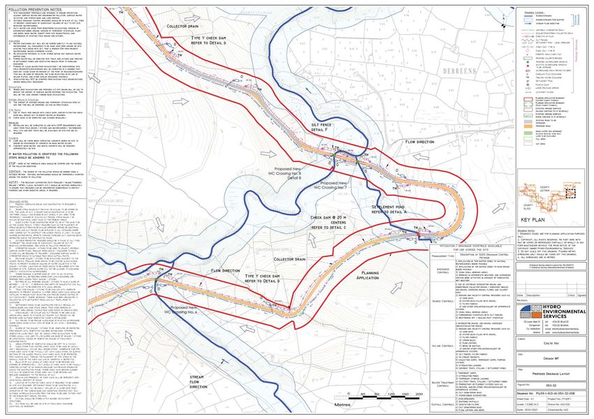
Croagh Wind Farm, Co. Leitrim & Co. SligoCroagh Wind Farm, Co. Leitrim & Co. Sligo
                                                                                                                                                                            SWMP F - 2021.03.11 - 180511

     Table of Contents
1.   INTRODUCTION ................................................................................................................................... 1
2.   SURFACE WATER DRAINAGE DESIGN ....................................................................................... 2
     2.1           Existing Drainage Features ................................................................................................................... 2
     2.2           Drainage Design Principles ................................................................................................................... 2
     2.3           Best Practice Guidance ........................................................................................................................... 3
     2.4           Drainage System ......................................................................................................................................... 4
     2.5           Surface Water Drainage Measures .................................................................................................. 5
           2.5.1             Interceptor Drains .................................................................................................................................................. 5
           2.5.2             Swales ........................................................................................................................................................................... 5
           2.5.3             Check Dams............................................................................................................................................................... 6
           2.5.4             Level Spreader ......................................................................................................................................................... 6
           2.5.5             Piped Slope Drains ................................................................................................................................................. 7
           2.5.6             Vegetation Filters .................................................................................................................................................. 8
           2.5.7             Stilling Ponds ............................................................................................................................................................ 8
           2.5.8             Siltbuster ..................................................................................................................................................................... 9
           2.5.9             Silt Bags ..................................................................................................................................................................... 10
           2.5.10            Sedimats.................................................................................................................................................................... 10
           2.5.11            Culverts ....................................................................................................................................................................... 11
           2.5.12            Silt Fences ................................................................................................................................................................. 11
3.   SURFACE WATER DRAINAGE MANAGEMENT ...................................................................... 12
     3.1           Good Environmental Management During Construction ................................................... 12
     3.2           Drainage Measure Implementation and Management ........................................................ 13
           3.2.1             Pre-Construction Drainage ............................................................................................................................ 13
           3.2.2             Construction Phase Drainage ....................................................................................................................... 13
                   3.2.2.1        Preparative Site Drainage Management................................................................................................................. 13
                   3.2.2.2        Pre-emptive Site Drainage Management ............................................................................................................... 13
                   3.2.2.3        Reactive Site Drainage Management ....................................................................................................................... 14
           3.2.3             Operational Phase Drainage Management ........................................................................................... 15
     3.3           Activity Specific Drainage Control and Mitigation Measures .......................................... 15
           3.3.1             Forestry Felling ...................................................................................................................................................... 15
                   3.3.1.1        Forestry Felling Drainage Management .................................................................................................................. 17
           3.3.2             Borrow Pit Drainage ........................................................................................................................................... 18
           3.3.3             Peat and Spoil Repository Area Drainage.............................................................................................. 18
           3.3.4             Floating Road Drainage .................................................................................................................................... 18
           3.3.5             Cable Trench Drainage...................................................................................................................................... 18
           3.3.6             Refuelling, Fuel and Hazardous Materials Storage ........................................................................... 19
           3.3.7             Cement Based Products Control Measures......................................................................................... 19
     3.4           Construction Phase Drainage Inspections and Maintenance ......................................... 20
4.   SURFACE WATER QUALITY MONITORING ............................................................................. 22
           4.1.1             Pre-Construction Baseline Monitoring ...................................................................................................23
           4.1.2             Construction Phase Monitoring ..................................................................................................................23
                   4.1.2.1        Daily Visual Inspections ................................................................................................................................................... 23
                   4.1.2.2        Continuous Monitoring .................................................................................................................................................... 24
                   4.1.2.3        Monthly Laboratory Analysis ........................................................................................................................................ 24
                   4.1.2.4        Field Monitoring ................................................................................................................................................................... 24
                   4.1.2.5        Monitoring Parameters ................................................................................................................................................... 25
           4.1.3             Surface Water Monitoring Reporting.......................................................................................................25
           4.1.4             Post Construction Monitoring ......................................................................................................................25
                   4.1.4.1        Monthly Laboratory Analysis Sampling .................................................................................................................. 25

5.   COMPLIANCE AND REVIEW ........................................................................................................26
     5.1           Site Inspections and Auditing ........................................................................................................... 26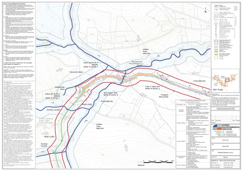
Croagh Wind Farm, Co. Leitrim & Co. SligoCroagh Wind Farm, Co. Leitrim & Co. Sligo
SWMP F - 2021.03.11 - 180511
1. INTRODUCTION
This Surface Water Management Plan (SWMP) is intended, as an accompanying document to the
Construction and Environmental Management Plan (CEMP), to compile the proposed surface water
drainage control and treatment measures, set out in the Environmental Impact Assessment Report
(EIAR), and the proposed surface water monitoring programme, set out in the CEMP, in a single
document.
This document has been prepared by Eoin McCarthy and reviewed by Michael Watson of MKO. Eoin
is a Senior Environmental scientist with over nine years’ experience with MKO and has been involved
in the development of surface water management plans for a number of wind energy EIARs in that
time. Michael Watson is a Project Director with MKO; with over 19 years’ experience in the
environmental sector. His project experience includes the management and production of
Environmental Impact Statements (EISs)/EIARs, particularly within the wind energy sector.
This document has also benefited from input by Michael Gill and David Broderick of Hydro
Environmental Services Ltd. (HES). HES were the authors of the Water chapter of the EIAR and also
designed the proposed drainage plan for the Croagh Wind Farm development that was submitted as
part of the planning application. Michael Gill is an Environmental Engineer with over 12 years’
environmental consultancy experience in Ireland. Michael has completed numerous hydrological and
hydrogeological impact assessments of wind farms in Ireland. David Broderick is a hydrogeologist with
over 9 years’ experience in both the public and private sectors.
This SWMP has been divided into three sections, as listed below, and draws and expands on
information already provided in Chapter 4 and Chapter 9 of the submitted EIAR and Section 4.2 of the
CEMP (Appendix 4-4 of the EIAR).
Surface Water Drainage Design
Surface Water Drainage Management
Surface Water Monitoring Programme
1
Croagh Wind Farm, Co. Leitrim & Co. SligoCroagh Wind Farm, Co. Leitrim & Co. Sligo
SWMP F - 2021.03.11 - 180511
2. SURFACE WATER DRAINAGE DESIGN
The drainage design for the Proposed Development has been prepared by Hydro Environmental
Services Ltd. (HES), and by the firm’s principal, Mr. Michael Gill. The protection of the watercourses
within and surrounding the site, and downstream catchments that they feed is of utmost importance in
considering the most appropriate drainage proposals for the site of the Proposed Development. The
Proposed Development’s drainage design has therefore been proposed specifically with the intention of
having no negative impact on the water quality of the site and its associated rivers and lakes, and
consequently no impact on downstream catchments and ecological ecosystems. No routes of any
natural drainage features will be altered as part of the Proposed Development and turbine locations and
associated new roadways were originally selected to avoid natural watercourses, and existing roads are
to be used wherever possible. There will be no direct discharges to any natural watercourses, with all
drainage waters being dispersed as overland flows. All discharges from the proposed works areas will
be made over vegetation filters at an appropriate distance from natural watercourses. Buffer zones of
100m and 50m around rivers and streams, respectively, have been used to inform the layout of the
Proposed Development.
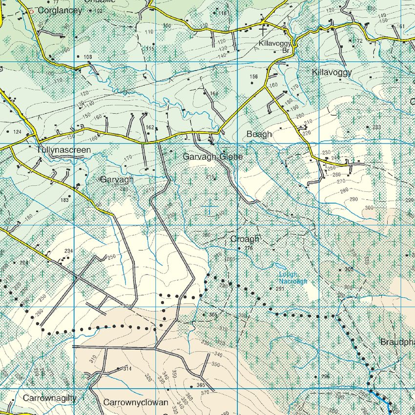
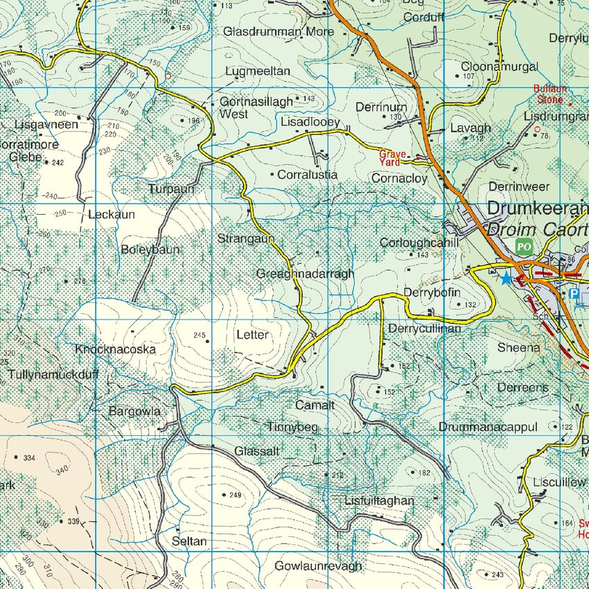
A copy of the drainage design drawing which are included in Appendix A of this document.
2.1 Existing Drainage Features
The routes of any natural drainage features will not be altered as part of the Proposed Development.
Turbine locations have been selected to avoid natural watercourses. Up to 9 no. new watercourse
crossings and 16 no. potential crossing upgrades will be required as part of the Proposed Development.
There will be no direct discharges to natural watercourses. All discharges from the proposed works
areas or from interceptor drains will be made over vegetated ground at an appropriate distance from
natural watercourses and lakes. Buffer zones around the existing natural drainage features have
informed the layout of the Proposed Development and are indicated on the drainage design drawings.
Where artificial drains are currently in place in the vicinity of proposed works areas, these drains may
have to be diverted around the proposed works areas to minimise the amount of water in the vicinity of
works areas. Where it may not be possible to divert artificial drains around proposed work areas, the
drains will be blocked to ensure sediment laden water from the works areas has no direct route to other
watercourses. Where drains have to be blocked, the blocking will only take place after the new
drainage system to handle the same water has been put in place.
Existing artificial drains in the vicinity of existing site roads will be maintained in their present location
where possible. If it is expected that these artificial drains will receive drainage water from works areas,
check dams will be added (as specified below) to control flows and sediment loads in these existing
artificial drains. If road widening or improvement works are necessary along the existing roads, where
possible, the works will take place on the opposite side of the road to the existing artificial drain.
2.2 Drainage Design Principles
Runoff control and drainage management are key elements in terms of mitigation against impacts on
surface water bodies. Two distinct methods will be employed to manage drainage water within the
Proposed Development. The first method involves ‘keeping clean water clean’ by avoiding disturbance
to natural drainage features, minimising any works in or around artificial drainage features, and
diverting clean surface water flow around excavations, construction areas and temporary storage areas.
The second method involves collecting any drainage waters from works areas within the site that might
carry silt or sediment, and nutrients, to route them towards stilling ponds prior to controlled diffuse
release over vegetated surfaces. There will be no direct discharges to surface waters. During the
2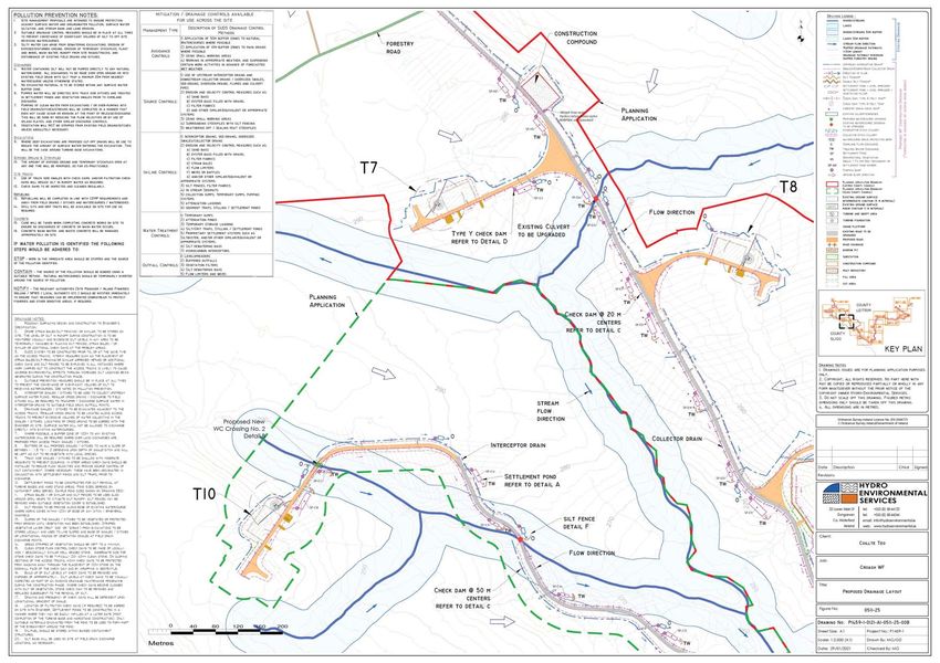
Croagh Wind Farm, Co. Leitrim & Co. SligoCroagh Wind Farm, Co. Leitrim & Co. Sligo
                                                                                                           SWMP F - 2021.03.11 - 180511

      construction phase all runoff from works areas (i.e. dirty water) will be attenuated and treated to a high
      quality prior to being released.

      The drainage design is intended to maximise erosion control, which is more effective than having to
      control sediment during high rainfall. Such a system also requires less maintenance. The area of
      exposed ground will be minimised. The drainage measures will prevent runoff from entering the works
      areas of the site from adjacent ground, to minimise the volume of sediment-laden water that has to be
      managed. Discoloured run-off from any construction area will be isolated (through the installation of
      drainage swales) from natural clean run-off.

      The proposed wind farm drainage process flow is presented in Figure 2-1 below.

      Figure 2-1 Proposed Wind Farm Drainage Process Flow

      Comprehensive surface water mitigation and controls are outlined below to ensure protection of all
      downstream receiving waters. Mitigation measures will ensure that surface runoff from the developed
      areas of the site will be of a high quality and will therefore not impact on the quality of downstream
      surface water bodies. Any introduced drainage works at the site will mimic the existing hydrological
      regime thereby avoiding changes to flow volumes leaving the site.

2.3   Best Practice Guidance
      The drainage design has been prepared based on experience of the project team of other renewable
      energy sites in peat-dominated environments, and a number of best practice guidance documents.

      There is no one guidance document that deals with drainage management and water quality controls
      for wind farms and other renewable energy developments. However, a selection of good practice
      approaches have been adopted in preparation of this drainage design, and these are taken from the

                                                                                                                                     3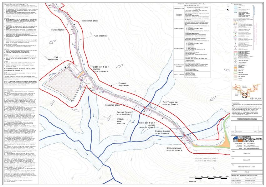
Croagh Wind Farm, Co. Leitrim & Co. SligoCroagh Wind Farm, Co. Leitrim & Co. Sligo
SWMP F - 2021.03.11 - 180511
various best practice guidance documents listed below. These relate to infrastructure and operational
works on forested sites, forest road design, water quality controls for linear projects, forestry road
drainage and management of geotechnical risks. To achieve best practice in terms of water protection
through construction management all drainage management is prepared in accordance with guidance
contained in the following:
Forestry Commission (2004): Forests and Water Guidelines, Fourth Edition. Publ.
Forestry Commission, Edinburgh;
Coillte (2009): Forest Operations & Water Protection Guidelines;
Forest Service (Draft): Forestry and Freshwater Pearl Mussel Requirements – Site
Assessment and Mitigation Measures;
Forest Service (2000): Forestry and Water Quality Guidelines. Forest Service, DAF,
Johnstown Castle Estate, Co. Wexford;
Forest Service, (2000): Code of Best Forest Practice – Ireland. Forest Service, DAF,
Johnstown Castle Estate, Co. Wexford;
COFORD (2004): Forest Road Manual – Guidelines for the design, construction and
management of forest roads;
MacCulloch (2006): Guidelines for risk management of peat slips on the construction
of low volume low cost roads over peat (Frank MacCulloch Forestry Civil
Engineering Forestry Commission, Scotland);
National Roads Authority (2005): Guidelines on Procedures for Assessment and
Treatment of Geology, Hydrology and Hydrogeology for National Road Schemes;
Wind Farm Development Guidelines for Planning Authorities (September 1996);
Eastern Regional Fisheries Board: Requirements for the Protection of Fisheries
Habitat during Construction and Development Works at River Sites;
Inland Fisheries Ireland (2016): Guidelines on Protection of Fisheries During
Construction Works Adjacent to Waters;
Scottish Natural Heritage, 2010: Good Practice During Wind Farm Construction;
PPG1 - General Guide to Prevention of Pollution (UK Guidance Note);
PPG5 – Works or Maintenance in or Near Water Courses (UK Guidance Note);
CIRIA Report No. C648 (2006): CIRIA (Construction Industry Research and
Information Association) guidance on ‘Control of Water Pollution from Linear
Construction Projects’;
CIRIA Report Number C532 (2001): Control of water pollution from construction
sites - Guidance for consultants and contractors.; and,
Control of water pollution from linear construction projects -Technical guidance.
CIRIA C648 London, 2006.
2.4 Drainage System
The early establishment of the drainage measures outlined in Section 2.5 below will manage the risk of
impacts on watercourses on and adjacent to the site during construction. In addition, construction
operations will adopt best working practices. The development of the site will need to be phased
accordingly. The construction of the drainage will start from the downstream sections and progress
upstream, connecting conveyance systems with other drainage features as each development phase
progresses. They will therefore need to be designed with sufficient flexibility and capacity to respond to
an early phase incoming flow during the construction phase.
The implementation of a Scheduling of Works Operating Record (SOWOR) prior to commencement
will provide a series of pre-commencement triggers which set out specific conditions which will be met
before the commencement of works in? particularly sensitive areas. These pre-commencement triggers
will apply to the installation of any drainage infrastructure. An example of an SOWOR is included in
Appendix B.
4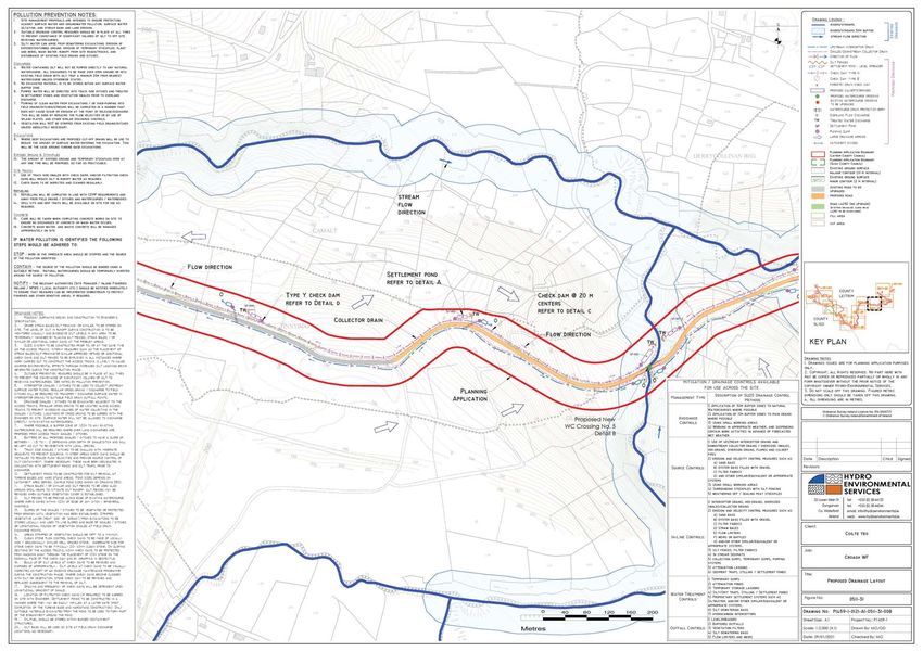
Croagh Wind Farm, Co. Leitrim & Co. SligoCroagh Wind Farm, Co. Leitrim & Co. Sligo
                                                                                                         SWMP F - 2021.03.11 - 180511

        The detailed drainage measures proposed to address surface water management based upon the design
        criteria and philosophy will be implemented. The drainage system will be excavated and constructed in
        conjunction with the road and hard standing construction. Drains will be excavated, and settlement
        ponds constructed to eliminate any suspended solids within surface water running off the site.

2.5     Surface Water Drainage Measures
2.5.1   Interceptor Drains
        Interceptor drains will be installed upgradient of any works areas to collect surface flow runoff and
        prevent it reaching excavations and construction areas of the site where it might otherwise have come
        into contact with exposed surfaces and picked up silt and sediment. The drains will be used to divert
        upslope runoff around the works area to a location where it can be redistributed over the ground
        surface as sheet flow. This will minimise the volume of potentially silty runoff to be managed within the
        construction area.

        The interceptor drains will be installed in advance of any main construction works commencing. The
        material excavated to make the drain will be compacted on the downslope edge of the drain to form a
        diversion dike. On completion of the construction phase works, it is envisaged that the majority of the
        interceptor drains could be removed. At that stage, there will be no open excavations or large areas of
        exposed ground that are likely to give rise to large volumes of potentially silt-laden run off. Any areas in
        which works were carried out to construct roads, turbine bases or hardstands, will have been built up
        with large grade hardcore, which even when compacted in place, will retain sufficient void space to
        allow water to infiltrate the subsurface of these constructed areas. It is not anticipated that roadways or
        other installed site infrastructure will intercept ground-conveyed surface water runoff to any significant
        extent that would result in scouring or over-topping or spill over. Where the drains are to be removed,
        they will be backfilled with the material from the diversion dike. Interceptor drains may have to be
        retained in certain locations, for example where roadways are to be installed on slopes, to prevent the
        roadways acting of conduits for water that might infiltrate the roadway sub-base. In these cases,
        interceptor drains will be maintained in localised areas along the roadway with culverts under the
        roadway, which will allow the intercepted water to be discharged to vegetation filters downgradient of
        the roadway. Similarly, in localised hollows where water is likely to be funnelled at greater
        concentrations than on broader slopes, interceptor drains, and culverts may be left in situ following
        construction.

        The velocity of flow in the interceptor will be controlled by check dams (see Section 2.5.3 below),
        which will be installed at regular intervals along the drains to ensure flow in the channel is non-erosive.
        On steeper sections where erosion risks are greater, a geotextile membrane will be added to the
        channel.

        Interceptor drains will be installed horizontally across slopes to run in parallel with the natural contour
        line of the slope. Intercepted water will travel along the interceptor drains to areas downgradient of
        works areas, where the drain will terminate at a level spreader (see Section 2.5.4 below). Across the
        entire length of the interceptor drains, the design elevation of the water surface along the route of the
        drains will not be lower than the design elevation of the water surface in the outlet at the level spreader.
        An illustration of an interceptor drain is shown in Figure 2-2.

2.5.2   Swales
        Drainage swales (or collector drains) are shallow drains that will be used to intercept and collect run off
        from construction areas of the site during the construction phase. Drainage swales will remain in place
        to collect runoff from roads and hardstanding areas of the proposed development during the
        operational phase. A swale is an excavated drainage channel located along the downgradient perimeter
        of construction areas, used to collect and carry any potentially sediment-laden runoff to a sediment-

                                                                                                                                   5
)LJXUH "
"
&URDJK:LQG)DUP
(RLQ0F&DUWK\
$
!"#$%&%'()
*%&+ , -./ 0 !1 ,0/ 0 
Croagh Wind Farm, Co. Leitrim & Co. SligoCroagh Wind Farm, Co. Leitrim & Co. Sligo
                                                                                                        SWMP F - 2021.03.11 - 180511

        trapping facility and stabilised outlet. Swales are proven to be most effective when a dike is installed on
        the downhill side. They are similar in design to interceptor drains and collector drains described above.

        Drainage swales will be installed downgradient of any works areas to collect surface flow runoff where it
        might have come into contact with exposed surfaces and picked up silt and sediment. Swales will
        intercept the potentially silt-laden water from the excavations and construction areas of the site and
        prevent it reaching natural watercourses.

        Drainage swales will be installed in advance of any main construction works commencing. The material
        excavated to make the swale will be compacted on the downslope edge of the drain to form a diversion
        dike. An illustration of a drainage swale is shown in Figure 2-2.

2.5.3   Check Dams
        The velocity of flow in the interceptor drains and drainage swales, particularly on sloped sections of the
        channel, will be controlled by check dams, which will be installed at regular intervals along the drains
        to ensure flow in the swale is non-erosive. Check dams will also be installed in some existing artificial
        drainage channels that will receive waters from works areas of the site.

        Check dams will restrict flow velocity, minimise channel erosion and promote sedimentation behind the
        dam. The check dams will be installed as the interceptor drains are being excavated.

        The proposed check dams will be made up of straw bales (temporary use only) or stone, or a
        combination of both depending on the size of the drainage swale it is being installed in. Where straw
        bales are to be used, they will be secured to the bottom of the drainage swale with stakes. Clean 4-6
        inch stone will be built up on either side and over the straw bale to a maximum height of 600mm over
        the bottom of the interceptor drain. In smaller channels, a stone check dam will be installed and
        pressed down into place in the bottom of the drainage swale with the bucket of an excavator.

        The check dams will be installed at regular intervals along the interceptor drains to ensure the bottom
        elevation of the upper check dam is at the same level as the top elevation of the next down-gradient
        check dam in the drain. The centre of the check dam will be approximately 150mm lower than the
        edges to allow excess water to overtop the dam in flood conditions rather than cause upstream flooding
        or scouring around the dams.

        Check dams will not be used in any natural watercourses, only artificial drainage channels and
        interceptor drains. The check dams will be left in place at the end of the construction phase to limit
        erosive linear flow in the drainage swales during extreme rainfall events.

        Check dams are designed to reduce velocity and control erosion and are not specifically designed or
        intended to trap sediment, although sediment is likely to build up. If necessary, any excess sediment
        build up behind the dams will be removed. For this reason, check dams will be inspected and
        maintained regularly to insure adequate performance. Maintenance checks will also ensure the centre
        elevation of the dam remains lower than the sides of the dam. An illustration of a check dam is shown
        in Figure 2-2.

2.5.4   Level Spreader
        A level spreader will be constructed at the end of each interceptor drain to convert concentrated flows
        in the drain, into diffuse sheet flow on areas of vegetated ground. The levels spreaders will be located
        downgradient of any proposed works areas in locations where they will not contribute further to water
        ingress to construction areas of the site.

        The water carried in interceptor drains will not have come in contact with works areas of the site, and
        therefore should be free of silt and sediment. The level spreaders will distribute clean drainage water

                                                                                                                                  6
Croagh Wind Farm, Co. Leitrim & Co. SligoCroagh Wind Farm, Co. Leitrim & Co. Sligo
SWMP F - 2021.03.11 - 180511
onto vegetated areas where the water will not be reconcentrated into a flow channel immediately below
the point of discharge. The discharge point will be on level or only very gently sloping ground rather
than on a steep slope so as to prevent erosion.
The slope in the channel leading into the spreader will be less than or equal to 1%. The slope
downgradient of the spreader onto which the water will dissipate will have a grade of less than 6%. The
availability of slopes with a grade of 6% or less will determine the locations of level spreaders. If a slope
grade of less than 6% is not available in the immediate area downgradient of a works area at the end of
a diversion drain, a piped slope drain (see Section 2.5.5 below) will be used to transfer the water to a
suitable location.
The spreader lip over which the water will spill will be made of a concrete kerb, wooden board, pipe,
or other similar piece of material that can create a level edge similar in effect to a weir. The spreader
will be level across the top and bottom to prevent channelised flow leaving the spreader or ponding
occurring behind the spreader. The top of the spreader lip will be 150mm above the ground behind it.
The length of the spreader will be a minimum of four metres and a maximum length of 25 metres, with
the actual length of each spreader to be determined by the size of the contributing catchment, slope
and ground conditions.
Clean four-inch stone can be placed on the outside of the spreader lip and pressed into the ground
mechanically to further dissipate the flow leaving the level spreader over a larger area. An illustration of
a level spreader is shown in Figure 2-2.
2.5.5 Piped Slope Drains
Piped slope drains will be used to convey surface runoff from diversion drains safely down slopes to flat
areas without causing erosion. Once the runoff reaches the flat areas it will be reconverted to diffuse
sheet flow. Level spreaders will only be established on slopes of less than 6% in grade. Piped slope
drains will be used to transfer water away from areas where slopes are too steep to use level spreaders.
The piped slope drains will be semi-rigid corrugated pipes with a stabilised entrance and a rock apron
at the outlet to trap sediment and dissipate the energy of the water. The base of drains leading into the
top of the piped slope drain will be compacted and concavely formed to channel the water into the
corrugated pipe. The entrance at the top of the pipe will be stabilised with sandbags if necessary. The
pipe will be anchored in place by staking at approximately 3-4 metre intervals or by weighing down
with compacted soil. The bottom of the pipe will be placed on a slope with a grade of less than 1% for a
length of 1.5 metres, before outflowing onto a rock apron.
The rock apron at the outlet will consist of 6-inch stone to a depth equal to the diameter of the pipe, a
length six times the diameter of the pipe. The width of the rock apron will be three times the diameter
of the pipe where the pipe opens onto the apron and will fan out to six times the diameter of the pipe
over its length.
Piped slope drains will only remain in place for the duration of the construction phase of the Proposed
Development. On completion of the works, the pipes and rock aprons will be removed, and all
channels backfilled with the material that was originally excavated from them.
Piped slope drains will be inspected weekly and following rainfall events. Inlet and outlets will be
checked for sediment accumulation and blockages. Stake anchors or fill over the pipe will be checked
for settlement, cracking and stability. Any seepage holes where pipe emerges from drain at the top of
the pipe will be repaired promptly. An illustration of a piped slope drain is shown in Figure 2-2.
7Croagh Wind Farm, Co. Leitrim & Co. SligoCroagh Wind Farm, Co. Leitrim & Co. Sligo
SWMP F - 2021.03.11 - 180511
2.5.6 Vegetation Filters
Vegetation filters are the existing vegetated areas of land that will be used to accept surface water runoff
from upgradient areas. The selection of suitable areas to use as vegetation filters will be determined by
the size of the contributing catchment, slope and ground conditions.
Vegetation filters will carry outflow from the level spreaders as overland sheet flow, removing any
suspended solids and discharging to the groundwater system by diffuse infiltration.
Vegetation filters will not be used in isolation for waters that are likely to have higher silt loadings. In
such cases, silt-bearing water will already have passed through stilling ponds prior to diffuse discharge
to the vegetation filters via a level spreader.
2.5.7 Stilling Ponds
Stilling or settlement ponds will be used to attenuate runoff from works areas of the site of the Proposed
Development during the construction phase and will remain in place to handle runoff from roads and
hardstanding areas of the proposed development during the operational phase. The purpose of the
stilling ponds is to intercept runoff potentially laden with sediment and to reduce the amount of
sediment leaving the disturbed area by reducing runoff velocity. Reducing runoff velocity will allow
larger particles to settle out in the stilling ponds, before the run-off water is redistributed as diffuse sheet
flow in filter strips downgradient of any works areas.
Stilling ponds will be excavated/constructed to the appropriate size at each required location as shown
on the drainage design drawings included in Appendix A of this document. The points at which water
enters and exits the stilling ponds will be stabilised with rock aprons, which will trap sediment, dissipate
the energy of the water flowing through the stilling pond system, and prevent erosion. The stilling
ponds will reduce the velocity of flows in order to allow settlement of silt to occur. Water will flow out
of the stilling pond through a stone dam, partially wrapped in geo-textile membrane, which will control
flow velocities and trap any sediment that has not settled out.
Water will flow by gravity through the stilling pond system. The stilling ponds have been sized
according to the size of the area they will be receiving water from and are large enough to
accommodate a 10-year return rainfall event. The settlement ponds are designed for 11hr and 24hr
retention times used to settle out medium silt (0.006mm) and fine silt (0.004mm) respectively (EPA,
2006)1. The stilling ponds will be dimensioned so that the length to width ratio will be greater than 2:1,
where the length is the distance between the inlet and the outlet. Where ground conditions allow,
stilling ponds will be constructed in a wedge shape, with the inlet located at the narrow end of the
wedge. Each stilling pond will be a minimum of 1-1.5 metres in depth. Deeper ponds will be used to
minimise the excavation area needed for the required volume.
The embankment that forms the sloped sides of the stilling ponds will be stabilised with vegetated
turves, which will have been removed during the excavation of the stilling ponds area.
Stilling ponds will be located towards the end of swales, close to where the water will be reconverted to
diffuse sheet flow. Upon exiting the stilling pond system, water will be immediately reconverted to
diffuse flow via a fan-shaped rock apron if there is adequate space and ground conditions allow.
Otherwise, a swale will be used to carry water exiting the stilling pond system to a level spreader to
reconvert the flow to diffuse sheet flow.
A water level indicator such as a staff gauge will be installed in each stilling pond with marks to identify
when sediment is at 10% of the stilling pond capacity. Sediment will be cleaned out of the still pond
1 Environmental Management Guidelines - Environmental Management in the Extractive Industry (Non-Scheduled Minerals)
(EPA, 2006)
8Croagh Wind Farm, Co. Leitrim & Co. SligoCroagh Wind Farm, Co. Leitrim & Co. Sligo
SWMP F - 2021.03.11 - 180511
when it exceeds 10% of pond capacity. Stilling ponds will be inspected weekly and following rainfall
events. Inlet and outlets will be checked for sediment accumulation and anything else that might
interfere with flows. An illustration of a stilling pond is shown in Figure 2-2.
2.5.8 Siltbuster
A “siltbuster” or similar equivalent piece of equipment will be available to filter any water pumped out
of excavation areas, if necessary, prior to its discharge to stilling ponds or swales.
Siltbusters are mobile silt traps that can remove fine particles from water using a proven technology and
hydraulic design in a rugged unit. The mobile units are specifically designed for use on construction
sites.
The unit stills the incoming water/solids mix and routes it upwards between a set of inclined plates for
separation. Fine particles settle onto the plates and slide down to the base for collection, whilst treated
water flows to an outlet weir after passing below a scum board to retain any floating material. The
inclined plates dramatically increase the effective settling area of the unit giving it a very small footprint
on site and making it highly mobile. Figure 2-2 below shows an illustrative diagram of the Siltbuster.
The Siltbuster units are now considered best practice for the management of dirty water pumped from
construction sites. The UK Environment Agency and the Scottish Environmental Protection Agency
have all recommended/specified the use of Siltbuster units on construction projects.
Figure 2-2 Siltbuster (Source: https://www.siltbuster.co.uk/sb_prod/siltbuster-fb50-settlement-unit/)
9Croagh Wind Farm, Co. Leitrim & Co. SligoCroagh Wind Farm, Co. Leitrim & Co. Sligo
SWMP F - 2021.03.11 - 180511
2.5.9 Silt Bags
Dewatering silt bags allow the flow of water through them while trapping any silt or sediment
suspended in the water. The silt bags provide a passive non-mechanical method of removing any
remaining silt contained in the potentially silt-laden water collected from works areas within the site.
Dewatering silt bags are an additional drainage measure that can be used downgradient of the stilling
ponds at the end of the drainage swale channels and will be located, wherever it is deemed
appropriate, throughout the site. The water will flow, via a pipe, from the stilling ponds into the silt bag.
The silt bag will allow the water to flow through the geotextile fabric and will trap any of the finer silt
and sediment remaining in the water after it has gone through the previous drainage measures. The
dewatering silt bags will ensure that there will be no loss of peaty silt into the stream.
The dewatering silt bag that will be used will be approximately 3 metres in width by 4.5 metres (see
Plate 2-1 and Plate 2-2 below) in length and will be capable of trapping approximately four tonnes of
silt. The dewatering silt bag, when full, will be removed from site by a waste contractor with the
necessary waste collection permit, who will then transport the silt bag to an appropriate, fully licensed
waste facility.
Plate 2-1 Silt Bag under inspection Plate 2-2 Silt Bag with water being pumped through
2.5.10 Sedimats
Sediment entrapment mats, consisting of coir or jute matting, will be placed at the outlet of the silt bag
to provide further treatment of the water outfall from the silt bag. Sedimats will be secured to the
ground surface using stakes/pegs. The sedimat will extend to the full width of the outfall to ensure all
water passes through this additional treatment measure as shown in Plate 2-3 below.
Plate 2-3 Typical Sedimat Details (Source: https://www.hy-tex.co.uk/)
10Croagh Wind Farm, Co. Leitrim & Co. SligoCroagh Wind Farm, Co. Leitrim & Co. Sligo
SWMP F - 2021.03.11 - 180511
2.5.11 Culverts
All new proposed culverts and proposed culvert upgrades will be suitably sized for the expected peak
flows in the watercourse.
Some culverts may be installed to manage drainage waters from works areas of the proposed
development, particularly where the waters have to be taken from one side of an existing roadway to
the other for discharge. The size of culverts will be influenced by the depth of the track or road sub-
base. In some cases, two or more smaller diameter culverts may be used where this depth is limited,
though this will be avoided as they will have a higher associated risk of blockage than a single, larger
pipe. In all cases, culverts will be oversized to allow mammals to pass through the culvert.
Culverts will be installed with a minimum internal gradient of 1% (1 in 100). Smaller culverts will have a
smooth internal surface. Larger culverts may have corrugated surfaces which will trap silt and
contribute to the stream ecosystem. Depending on the management of water on the downstream side of
the culvert, large stone may be used to interrupt the flow of water. This will help dissipate its energy
and help prevent problems of erosion. Smaller water crossings will simply consist of an appropriately
sized pipe buried in the sub-base of the road at the necessary invert level to ensure ponding or pooling
doesn’t occur above or below the culvert and water can continue to flow as necessary.
All culverts will be inspected regularly to ensure they are not blocked by debris, vegetation or any
other material that may impede conveyance.
2.5.12 Silt Fences
Silt fences will be installed as an additional water protection measure around existing watercourses in
certain locations, particularly where works are proposed within the 50-metre buffer zone of a natural
watercourse, which is inevitable where existing roads in proximity to watercourses are to be upgraded
as part of the proposed development. These areas include around existing culverts, around the
headwaters of watercourses, and the proposed locations are indicated on the detailed drainage design
drawings included in Appendix A of this document.
Silt fences will be installed as single, double or a series of triple silt fences, depending on the space
available and the anticipated sediment loading. The silt fence designs follow the technical guidance
document ‘Control of Water Pollution from Linear Construction Projects’ published by CIRIA (Ciria,
No. C648, 1996). Up to three silt fences may be deployed in series.
All silt fencing will be formed using Terrastop Premium or equivalent silt fence product.
Site fences will be inspected regularly to ensure water is continuing to flow through the fabric, and the
fence is not coming under strain from water backing up behind it.
Site fences will be inspected regularly to ensure water is continuing to flow through the fabric, and the
fence is not coming under strain from water backing up behind it. Typical silt fence details are shown
below in Plate 2.4.
11Croagh Wind Farm, Co. Leitrim & Co. SligoCroagh Wind Farm, Co. Leitrim & Co. Sligo
SWMP F - 2021.03.11 - 180511
Plate 2-4 Typical Silt Fence Details
3. SURFACE WATER DRAINAGE
MANAGEMENT
The following sections give an outline of drainage management arrangements in terms of pre-
construction, construction and operational phases of the Proposed Development.
3.1 Good Environmental Management During
Construction
Timing of works can strongly influence the potential for damaging the freshwater environment.
Operations during wetter periods of the year pose a significantly greater risk of causing erosion and
siltation, which can be particularly severe following major rainfall or snowmelt events. Traditionally,
wind farm construction undertaken during the drier summer months will result in significantly less
erosion and siltation. Construction activities in the hydrological buffer zones shall be avoided during or
after prolonged rainfall or an intense rainfall event and work will cease entirely near watercourses when
it is evident that water quality could potentially be impacted. Given that this site has an established
drainage network and existing watercourse crossing points, there will be no adverse impacts on
watercourses.
12Croagh Wind Farm, Co. Leitrim & Co. SligoCroagh Wind Farm, Co. Leitrim & Co. Sligo
SWMP F - 2021.03.11 - 180511
3.2 Drainage Measure Implementation and
Management
3.2.1 Pre-Construction Drainage
There is an existing drainage network across the site. There are four main watercourses which drain the
proposed development site and there are numerous manmade drains that are in place predominately to
drain the forestry plantations This existing drainage system will continue to function as it is during the
pre-construction phase.
However, prior to commencement of works in sub-catchments across the site, main drain inspections
will be competed to ensure ditches and streams are free from debris and blockages that may impede
drainage. It is proposed to complete these inspections on a catchment by catchment basis as the
construction works develop across the site, as works in all areas will not commence simultaneously.
3.2.2 Construction Phase Drainage
The Project Hydrologist will attend the site to set out and assist with the implementation of the
proposed drainage controls as outlined in Section 2.5 above and shown in the drainage design drawings
included in Appendix A. The drainage system will be excavated and constructed in conjunction with
the road and hard standing construction. Drains will be excavated and stilling ponds constructed to
eliminate any suspended solids within surface water running off the site.
The implementation of a Schedule of Works Operation Record (SOWOR) will continue through the
construction phase of the project. The SOWOR provides number of abandonment triggers which will
ensure that site management are well informed as to the level of incident that will require the
abandonment of works. The various triggers both pre-commencement and abandonment ensure best
practice in terms of water quality management is maintained prior to commencement and during the
various felling and construction phases.
Best practice and practical experience on other similar projects suggest that in addition to the drainage
plans that are included in and as part of this application, there are additional site based decisions that
can only be made in the field through interaction between the Site Construction Manager, the Project
Hydrologist and the Project Geotechnical Engineers. The mechanisms for interaction between these are
outlined within Section 4 of the CEMP.
In relation to decisions that are made on site it is important to stress that these will be implemented in
line with the associated drainage controls and mitigation measures outlined in Section 2.5 above and
3.3 below, and to ensure protection of all watercourses.
3.2.2.1 Preparative Site Drainage Management
All materials and equipment necessary to implement the drainage measures outlined above will be
brought on-site in advance of any works commencing.
An adequate quantity of straw bales, clean stone, terram, stakes, etc. will be kept on site at all times to
implement the drainage design measures as necessary. The drainage measures outlined in the above
will be installed prior to, or at the same time as the works they are intended to drain.
3.2.2.2 Pre-emptive Site Drainage Management
The works programme for the initial construction stage of the development will also take account of
weather forecasts and predicted rainfall in particular. Large excavations and movements of peat/subsoil
13Croagh Wind Farm, Co. Leitrim & Co. SligoCroagh Wind Farm, Co. Leitrim & Co. Sligo
SWMP F - 2021.03.11 - 180511
or vegetation stripping will be suspended or scaled back if heavy rain is forecast. The extent to which
works will be scaled back or suspended will relate directly to the amount of rainfall forecast.
The following forecasting systems are available and will be used on a daily basis at the site to direct
proposed construction activities:
General Forecasts: Available on a national, regional and county level from the Met Eireann
website (www.met.ie/forecasts). These provide general information on weather patterns
including rainfall, wind speed and direction but do not provide any quantitative rainfall
estimates;
MeteoAlarm: Alerts to the possible occurrence of severe weather for the next 2 days. Less
useful than general forecasts as only available on a provincial scale;
3-hour Rainfall Maps: Forecast quantitative rainfall amounts for the next 3 hours but does
not account for possible heavy localised events;
Rainfall Radar Images: Images covering the entire country are freely available from the
Met Eireann website (www.met.ie/latest/rainfall_radar.asp). The images are a composite of
radar data from Shannon and Dublin airports and give a picture of current rainfall extent
and intensity. Images show a quantitative measure of recent rainfall. A 3-hour record is
given and is updated every 15 minutes. Radar images are not predictive; and,
Consultancy Service: Met Eireann provide a 24-hour telephone consultancy service. The
forecaster will provide interpretation of weather data and give the best available forecast
for the area of interest.
Using the safe threshold rainfall values will allow work to be safely controlled (from a water quality
perspective) in the event of forecasting of an impending high rainfall intensity event.
Works will be suspended if forecasting suggests either of the following is likely to occur:
>10 mm/hr (i.e. high intensity local rainfall events);
>25 mm in a 24-hour period (heavy frontal rainfall lasting most of the day); or,
>half monthly average rainfall in any 7 days.
Prior to works being suspended the following control measures shall be completed:
Secure all open excavations;
Provide temporary or emergency drainage to prevent back-up of surface runoff; and,
Avoid working during heavy rainfall and for up to 24 hours after heavy events to ensure
drainage systems are not overloaded.
3.2.2.3 Reactive Site Drainage Management
The detailed drainage plan prepared for the site has provided for reactive management of drainage
measures. The effectiveness of drainage measures designed to minimise runoff entering works areas and
capture and treat potentially silt-laden water from the works areas, will be monitored continuously by
the Environmental Clerk of Works (ECoW) on-site. The ECoW or project hydrologist will respond to
changing weather, ground or drainage conditions on the ground as the project proceeds, to ensure the
effectiveness of the drainage design is maintained in so far as is possible. This may require the
installation of additional check dams, interceptor drains or swales as deemed necessary on-site. The
drainage design may have to be modified on the ground as necessary, and the modifications will draw
on the various features outlined above in whatever combinations are deemed to be most appropriate to
the situation on the ground at a particular time.
In the unlikely event that works are giving rise to siltation of watercourses, the ECoW or project
hydrologist will stop all works in the immediate area around where the siltation is evident. The source
14Croagh Wind Farm, Co. Leitrim & Co. SligoCroagh Wind Farm, Co. Leitrim & Co. Sligo
SWMP F - 2021.03.11 - 180511
of the siltation will be identified and additional drainage measures such as those outlined in Section 2.5
above will be installed in advance of works recommencing.
3.2.3 Operational Phase Drainage Management
The project hydrologist will inspect and review the drainage system after construction has been
completed to provide guidance on the requirements of an operational phase drainage system. This
operational phase drainage system will have been installed during the construction phase in conjunction
with the road and hardstanding construction work as described below:
Some interceptor drains will be left in place, upgradient of the proposed
infrastructure to collect clean surface runoff, in order to minimise the amount of
runoff reaching areas where suspended sediment could become entrained. It will
then be directed to areas where it can be re-distributed over the ground by means of
a level spreader.
Swales/road side drains will remain in place to intercept and collect runoff from
access roads and hardstanding areas of the site, likely to have entrained suspended
sediment, and channel it to stilling ponds for sediment settling;
Check dams will be put in place at regular intervals along interceptor drains and
swales/roadside drains in order to reduce flow velocities and therefore minimise
erosion within the system during storm rainfall events; and,
Stilling ponds/settlement ponds, emplaced downstream of swales and roadside drains,
will buffer volumes of runoff discharging from the drainage system during periods of
high rainfall, by retaining water until the storm hydrograph has receded, thus
reducing the hydraulic loading to watercourses. The stilling ponds will be sized
according to the size of the area they will be receiving water from, but will be
sufficiently large to accommodate peak flows storm events. Inspection and
maintenance of all settlement ponds, along with the entire drainage network, will be
ongoing through the construction period.
In the operational phase of the wind farm, the reliance on the drainage system summarised above will
become reduced as areas naturally revegetate. Once areas revegetate, this will result in a resumption of
the natural drainage management that will have existed prior to any construction.
3.3 Activity Specific Drainage Control and
Mitigation Measures
3.3.1 Forestry Felling
Tree felling to facilitate the Proposed Development will not be undertaken simultaneously with
construction groundworks. Keyhole felling to facilitate construction works will take place prior to
groundworks commencing.
Water protection measures will reduce the risk of entrainment of suspended solids and nutrient release
in surface watercourses. These measures are derived from best practice guidance documents as
outlined in Section 2.3 above. The water protection measures to be adopted during felling operations
are set out as follows:
Machine combinations (i.e. hand-held or mechanical) will be chosen which are most
suitable for ground conditions at the time of felling, and which will minimise soils
disturbance;
Trees will be cut manually inside the 50m buffer and using machinery to extract whole
trees only;
15Croagh Wind Farm, Co. Leitrim & Co. SligoCroagh Wind Farm, Co. Leitrim & Co. Sligo
SWMP F - 2021.03.11 - 180511
Checking and maintenance of roads and culverts will be on-going through any felling
operation. No tracking of vehicle through watercourses will occur, as vehicles will use road
infrastructure and existing watercourse crossing points. Where possible, existing drains will
not be disturbed during felling works;
Ditches which drain from the proposed area to be felled towards existing surface
watercourses will be blocked, and temporary silt traps will be constructed. No direct
discharge of such ditches to watercourses will occur. Drains and sediment traps will be
installed during ground preparation. Collector drains will be excavated at an acute angle
to the contour (~0.3%-3% gradient), to minimise flow velocities. Main drains to take the
discharge from collector drains will include water drops and rock armour, as required,
where there are steep gradients, and shall avoid being placed at right angles to the contour;
Sediment traps will be sited in drains downstream of felling areas. Machine access will be
maintained to enable the accumulated sediment to be excavated. Sediment will be carefully
disposed of in the peat disposal areas. Where possible, all new silt traps will be constructed
on even ground and not on sloping ground;
In areas particularly sensitive to erosion or where felling inside the 50 metre buffer is
required, it will be necessary to install double or triple sediment traps.
Double silt fencing will also be put down slope of felling areas which are located inside the
50 metre buffer zone;
All drainage channels will taper out before entering the aquatic buffer zone. This ensures
that discharged water gently fans out over the buffer zone before entering the aquatic zone,
with sediment filtered out from the flow by ground vegetation within the zone. On erodible
soils, silt traps will be installed at the end of the drainage channels, to the outside of the
buffer zone;
Drains and silt traps will be maintained throughout all felling works, ensuring that they are
clear of sediment build-up and are not severely eroded. Correct drain alignment, spacing
and depth will ensure that erosion and sediment build-up are minimized and controlled;
Brash mats will be used to support vehicles on soft ground, reducing peat and mineral soils
erosion and avoiding the formation of rutted areas, in which surface water ponding can
occur. Brash mat renewal shall take place when they become heavily used and worn.
Provision shall be made for brash mats along all off-road routes, to protect the soil from
compaction and rutting. Where there is risk of severe erosion occurring, extraction shall be
suspended during periods of high rainfall;
Timber will be stacked in dry areas, and outside a local 50 metre watercourse buffer. Straw
bales and check dams to be emplaced on the down gradient side of timber
storage/processing sites;
Works will be carried out during periods of no, or low rainfall, in order to minimise
entrainment of exposed sediment in surface water run-off;
Checking and maintenance of roads and culverts will be on-going through the felling
operation;
No crossing of streams by machinery will be permitted and only travel perpendicular to
and away from stream will be allowed;
Refuelling or maintenance of machinery will not occur within 100m of a watercourse.
Mobile bowser, drip kits, qualified personnel will be used where refuelling is required;
A permit to refuel system will be adopted at the site; and,
Branches, logs or debris will not be allowed to build up in aquatic zones. All such material
will be removed when harvesting operations have been completed, but care will be taken
to avoid removing natural debris deflectors.
16You can also read