Survey of the Status of Small Armed and Unarmed Uninhabited Aircraft - Eldorado
←
→
Page content transcription
If your browser does not render page correctly, please read the page content below
Preventive Arms Control for Small and Very Small Armed Aircraft
                          and Missiles

                         Report No. 1

     Survey of the Status of Small Armed and
          Unarmed Uninhabited Aircraft
        Mathias Pilch, Jürgen Altmann and Dieter Suter

                        February 2021

                Chair Experimental Physics III
                  TU Dortmund University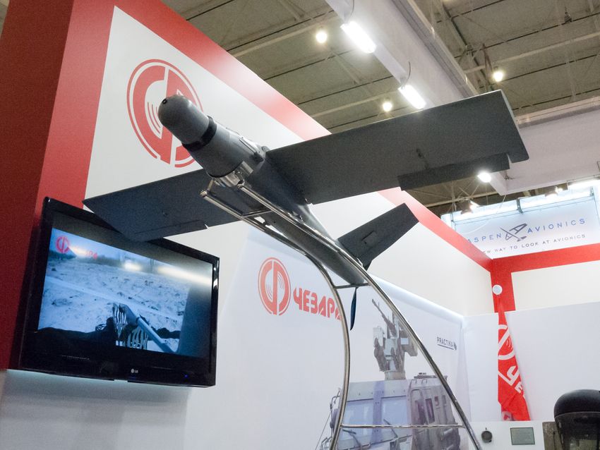
This report has been written in the research project ‘Preventive Arms Control for
Small and Very Small Armed Aircraft and Missiles’ of TU Dortmund University.
The project is being funded by the German Foundation for Peace Research (DSF,
https://bundesstiftung-friedensforschung.de/) in its funding line ‘New
Technologies: Risks and Chances for International Security and Peace’.

About the Authors
Mathias Pilch
Mathias Pilch, M.Sc, is a physicist and researcher at Technische Universität Dortmund,
Germany. In January 2018 he has finished his M.Sc. thesis about numerical modelling
of seismic tracked-vehicle signals for co-operative verification.

Jürgen Altmann
Jürgen Altmann, PhD, is a physicist and peace researcher at Technische Universität
Dortmund, Germany. Since 1985 he has studied scientific-technical problems of dis-
armament. Another focus is assessment of new military technologies and preventive
arms control.

Dieter Suter
Dieter Suter, Prof. Dr., is a physicist, researcher and professor at Technische Universität
Dortmund, Germany since 1995. His fields of interest are the development of advanced
magnetic resonance techniques, optically enhanced magnetic resonance, quantum in-
formation processing and medical physics applications of magnetic resonance.

(C) 2021. Except where otherwise noted, this work is available under a Creative
Commons Attribution-NonCommercial-NoDerivatives 4.0 International License CC
BY-NC-ND 4.0, see https://creativecommons.org/licenses/by-nc-nd/4.0/.
Contents

Abbreviations and Acronyms                             5

1 Introduction                                         6

2 Definitions and Classifications                       9
  2.1 Uninhabited Aircraft                              9
  2.2 Small and Very Small (Uninhabited) Aircraft      10

3 Aerodynamics                                         11

4 Technical Overview                                   17
  4.1 Airframe Configurations                          17
      4.1.1 Fixed-wing Configurations                  17
      4.1.2 Rotary-wing Configurations                 19
      4.1.3 Hybrid Configurations                      20
      4.1.4 Flapping Wings                             20
      4.1.5 Tethering                                  21
  4.2 Materials and Manufacturing                      21
  4.3 Power and Propulsion                             22
  4.4 Guidance and Navigation                          23
      4.4.1 Navigation and Autopilots                  23
      4.4.2 Control Stations                           24
  4.5 Launch and Recovery                              24
  4.6 Payloads                                         27
      4.6.1 Sensor Payloads                            27
      4.6.2 Offensive Payloads                         28

5 Research and Development Programmes in the USA       30
  5.1 The DARPA Nano Air Vehicle (NAV)                 30
  5.2 Lethal Miniature Aerial Missile System (LMAMS)   31
  5.3 Gremlins                                         31
  5.4 Perdix                                           32
  5.5 Low-Cost UAV Swarming Technology (LOCUST)        33
  5.6 Anubis                                           33

                                      3
Contents

   5.7    Cluster UAS Smart Munition for Missile Deployment   33
   5.8    Short Range Reconnaissance (SRR)                    33
   5.9    Offensive Swarm-Enabled Tactics (OFFSET)            33
   5.10   Air Launch Effects (ALE)                            34
   5.11   Air Force and Army MAV Programmes                   34

6 UAV Swarms                                                  36

7 UAV Countermeasures                                         37

8 Small and Very Small UAV Database                           39
  8.1 Database Properties                                     39
  8.2 General Overview                                        42
  8.3 Armed UAVs                                              46
  8.4 Parameter Distributions and Correlations                51
      8.4.1 Fixed- and rotary-wing UAVs                       52
      8.4.2 Flapping-wing UAVs                                57

9 Conclusion                                                  59

   Acknowledgements                                           60

   Bibliography                                               61

A Table of Small and Very Small UAVs                          66

   UAV Table References                                       78

                                       4
Abbreviations and Acronyms

AGL       Above ground level
AMSL      Above mean sea level
BAV       Biomimetic air vehicle
BDS       BeiDou navigation satellite system
C-UAS     Counter uninhabited aircraft system
COMINT    Communications intelligence
COTS      Commercial off-the-shelf
DARPA     Defense Advanced Research Projects Agency
EFP       Explosively formed penetrator
EO        Electro-optical
GCS       Ground control system
GLONASS   Global navigation satellite system
GNSS      Global navigation satellite system
GPS       Global positioning system
HTOL      Horizontal take-off and landing
ICAO      International Civil Aviation Organization
IMU       Inertial measurement unit
INS       Inertial navigation system
IR        Infrared
ISR       Intelligence, surveillance and reconnaissance
LiDAR     Light detection and ranging
LOCUST    Low-cost UAV swarming technology
LWIR      Long-wave infrared
MAV       Micro air vehicle
MEMS      Microelectromechanical systems
MTOW      Maximum take-off weight
MWIR      Midwave infrared
NAV       Nano Air Vehicle
NIR       Near infrared
PEO       Program Executive Office
R&D       Research and development
RF        Radio frequency
RPG       Rocket-propelled grenade
SCO       Strategic Capabilities Office
SWIR      Short-wave infrared
UA        Uninhabited aircraft
UAS       Uninhabited aerial system
UAV       Uninhabited aerial vehicle
VTOL      Vertical take-off and landing

                                   5
1 Introduction

    The project ‘Preventive Arms Control for Small and Very Small Armed Aircraft and
Missiles’, funded by the German Foundation for Peace Research DSF, is investigating
the properties to be expected of ever smaller aircraft and missiles, including their use
in swarms (https://url.tu-dortmund.de/pacsam). Small and very small aircraft
as covered here are uninhabited by their size, thus the designation uninhabited aerial
vehicle (UAV) or uninhabited aircraft (UA) applies. While the focus is on armed
systems, unarmed ones will be covered as well, since modifications for carrying or
acting as a weapon are possible. This report no. 1 covers the status of UAVs. Further
reports will deal with missiles and consider dangers and preventive arms control.
    Uninhabited vehicles are increasingly being deployed and used by armed forces, with
UAVs most advanced. Since 2001 UAVs have been armed and used for attacks by a
few states, the number of countries with armed UAVs is rising dramatically. In 2017,
there were 28 (World of Drones, 2017), while in 2020 the number rose to 39 (World of
Drones, 2020). These UAVs have wingspans of many metres.
    The principal possibility of small and very small armed UAVs and missiles was
mentioned early, fuelled by emerging microsystems technology and nanotechnology,
but proposals for limits or prohibitions1 have not been taken up so far. In the meantime,
the first small armed UAVs with a size of only very few metres, down to centimetres,
have arrived. Although small UAVs are far more limited in their capabilities than large
UAVs, they can be a considered a cheap alternative to larger systems that nevertheless
provides a basic level of aircraft capabilities.
    A rapid increase in popularity, availability, variety and capability of commercial
off-the-shelf (COTS) small UAVs over the past decade has led to an increase in usage
of these systems by non-state actors and armed groups. Usually much less sophisticated
than their military counterparts, improvised armed UAVs have been built and used by
non-state actors using commercial and hobby multicopters as well as home-built fixed-
wing UAVs. Because non-state actors are not the drivers of technology development,
their activities are mentioned only in this introduction. Activities by non-state actors
using small (here: mass < 25 kg) COTS UAVs are covered in (Friese et al., 2016). The
authors conclude that historically, the use of UAVs by non-state actors has been sporadic
and rudimentary. However, recent jumps in capabilities and availability of small COTS
UAVs, including smaller size and easier piloting, are leading to an increased use of
these systems by non-state actors. Non-state actors which have used COTS small UAVs
include, among others, Syrian militants, e.g. attacking Russian air and naval bases in
Syria (MacFarquhar, 2018; Binnie, 2018), the so-called Islamic State using them as
scouts or for attacks with explosive charges (Hambling, 2016), and non-state actors
in the Ukraine (Friese et al., 2016). Criminals have used small commercial UAVs to
illicitly transport narcotics between Mexico and the USA (Friese et al., 2016), as well
1   Mainly by (Altmann, 2001; Altmann, 2006): prohibition of missiles and ‘mobile micro-robots’ below
    0.2-0.5 m size.

                                                  6
1 Introduction

as weaponised modified versions for gang wars (Hambling, 2020b).
   In military small armed UAs a next step could be equipping them with missiles.
Traditional missiles such as the AGM-114 Hellfire (length: 163–175 cm, mass: 45-
48 kg (FAS, 2012)) are far too large and heavy for smaller UAVs. However, smaller
missiles have been developed, too, one intent being the wish to arm smaller UAVs.
Small and very small missiles will be covered in the next report.
   To assess the potential effects to be expected from small and very small armed aircraft
and missiles, including dangers to military stability and international security, as well as
options for preventive arms control, the first precondition is reliable information about
already existing systems and current trends in research and development.
   Based on databases, scientific and internet publications, this report lists small armed
UAVs deployed and used worldwide, as well as systems under research and development,
with their properties. Non-armed systems are included to investigate the global usage
of small UAVs and thus overall interest in smaller systems. This comprises non-armed
systems which could be provided with or used as weapons.
   In order to minimise a contribution to proliferation of these systems, only public
sources were investigated, i.e. the internet as well as publicly available databases and
catalogues. Furthermore, where information is incomplete, no estimates based on the
laws of physics or stemming from engineering expertise are given. Improvised or
modified versions of UAVs or missiles, already in use by non-state actors, are left out
for the same reason.
   The results of our research are collected in two databases, one each for the UAVs
and the missiles; here the one for the UAVs is covered. As far as has been available,
their basic properties with the year of introduction are listed to allow statements on
trends of UAV capabilities in recent years. Due to the sheer number of UAV types
available today, we focused mainly on UAVs intended to fulfil military roles, such
as reconnaissance or combat. An exception are UAVs that fall under the very small
category. There, most UAVs are still in the research or development stages and not
in military service nor designed for military use. However, research and development
(R&D) of some systems had been funded originally by military institutions (sections 5.1
and 5.11). In any case, these projects are important indicators of the future potential of
these small-sized aircraft.
   Similar work has been done by the Center for the Study of the Drone at Bard College
in the USA. In 2019, it released the Drone Databook (Gettinger, 2019) (with an update
in March 2020 (Gettinger, 2020)), evaluating the military drone capabilities of over 100
countries known to possess or operate uninhabited aircraft. It includes lists of military
UAV infrastructures and technical specifications of over 170 UAVs of all sizes.
   Technical specifications of so-called loitering munitions, a special variant of UAVs
equipped with a warhead and the ability to loiter in the air for an extended amount
of time before attacking with self-destruction, were collected in (Gettinger & Michel,
2017).
   An overview of countries that have conducted UAV attacks, that possess and develop
armed UAVs, including non-state-actor activities, is given in the World of Drones

                                             7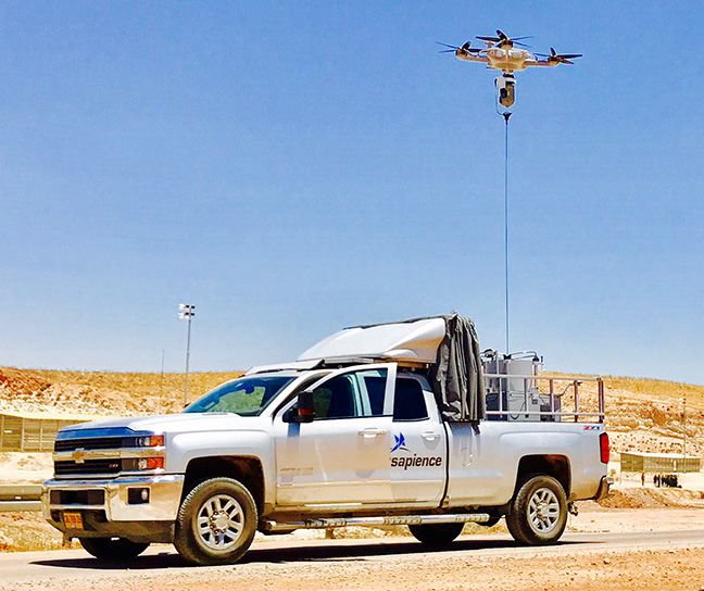
1 Introduction

database (World of Drones, 2020).
   In 2014, Cai et al. published a survey of ‘small-scale’ UAVs with a total of 132
civilian and military models (Cai et al., 2014). The UAVs collected vary in size from
less than ten metres down to centimetres. UAV properties are given only for a few
examples and far less detailed than in our database. The development of key UAV
elements, such as on-board processing units, sensors, communication modules etc. is
presented and analysed as well. Among the predictions for the near-term future (2-5
years) are an increased popularity in flapping-wing UAVs in research, as well as an
increasing demand of small-scale UAVs for military applications.
   In 2015, Ward et al. presented a bibliometric review of engineering and biology
articles published between 1984 and 2014 on so-called biomimetic air vehicles (BAVs),
flapping-wing UAVs that mimic the kinematics of flying organisms (Ward, Rezadad
et al., 2015). The general focus of articles is aerodynamics, guidance and control,
mechanisms, structures and materials, and system design, with a rapid increase in
publications since 2005. Most research was done in the United States, South Korea,
Japan, the United Kingdom and China. The authors expect an increase in numbers and
variety of bio-mimicry species as technological challenges are overcome.
   This article was followed by Ward et al. in 2017 with a bibilometric review on micro
air vehicles (MAVs) between the years 1998 and 2015 (Ward, Fearday et al., 2017). The
majority of research articles were written in the USA, China, UK, France and South
Korea. The authors conclude that biomimetic MAVs are most popular, rivalled by a
growing popularity of rotary-wing MAVs.
   The focus of the present report is on small and very small UAVs. Before we present
the results of the data collection, we need to establish a technical background and factual
information. Chapter 2 lays a terminology basis and chapter 3 presents basic aspects
of aerodynamics. Chapter 4 gives a technical overview, with subchapters on airframe
configurations, materials and manufacturing, power and propulsion, guidance, launch
and recovery and payloads.1 Research and development in the USA are the subject of
chapter 5. Swarms and countermeasures are treated in Chapters chapter 6 and chapter 7,
respectively. Chapter 8 presents summary properties of the database which itself is
presented in the appendix A and at an internet location.2

1   Since many aspects of communication to and from UAVs apply in general and are not specific to small
    UAVs, they are not discussed here; they are covered in (Gundlach, 2012, ch. 12). MAV communication
    is treated in (Michelson, 2015).
2   https://url.tu-dortmund.de/pacsam for the project description and https://url.tu-dortm
    und.de/pacsam-db for a description of the databases. The small and very small aircraft database is
    available at https://url.tu-dortmund.de/pacsam-db-sa.

                                                   8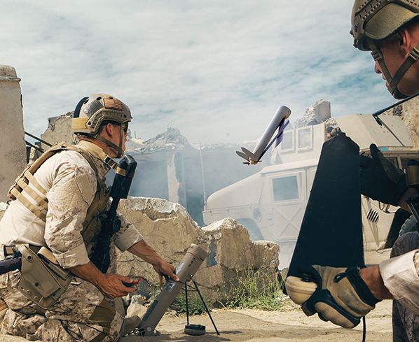
2 Definitions and Classifications

2.1 Uninhabited Aircraft
There exist many different definitions of a UA given by institutions, policymakers or by
individual scientists in research articles. We use the term UA and UAV synonymously
for an uninhabited aircraft, following the definitions of the International Civil Aviation
Organization (ICAO) (definitions 2.1.1 and 2.1.2). However, instead of the ICAO’s use
of the term ‘unmanned’ we prefer the gender-neutral and more precise ‘uninhabited’
since uninhabited aircraft that are remotely piloted can still be considered ‘manned’.

   Definition 2.1.1: Aircraft
   Any machine that can derive support in the atmosphere from the reactions of the
   air other than the reactions of the air against the earth’s surface (ICAO, 2010,
   p. I-1). Consequently cruise and other guided or unguided missiles count as
   (uninhabited) aircraft, except ballistic missiles not using aerodynamic lift when
   travelling in the atmosphere.

   Definition 2.1.2: Uninhabited Aircraft
   Aircraft intended to be flown without a pilot on board (ICAO, 2020).

   The UA itself is part of an uninhabited aerial system (UAS), which in addition to the
aircraft includes all key elements required for a UA mission. These additional elements
are the payload, the communication data link, the launch and recovery element, the
human element and a command and control structure.
   Definition 2.1.1 includes so-called ‘loitering munitions’, which can be considered
as both a UA and a guided missile. Their purpose is to attack a target in the same
manner as a missile, e.g. with an explosive warhead. However, in contrast to a missile,
a loitering munition can spend an extended amount of time in the target zone and fly
a search pattern before attacking. Therefore, as long as the loitering munition is in
flight, the attack can still be called off, with the aircraft either returning back to base or
self-destructing in a chosen area, a capability that does not exist with most missiles.

   Definition 2.1.3: Loitering Munition
   An uninhabited aircraft with its main purpose to attack targets with a fixed built-
   in warhead (usually explosive) that leads to self-destruction of the aircraft. In
   contrast to missiles, it has the ability to loiter above a designated area before
   striking its target.

   Loitering munitions can appear in the same configurations as other UAs, i.e. as
rotary-wing, fixed-wing or any other aircraft type. A rotary-wing example is the IAI

                                              9
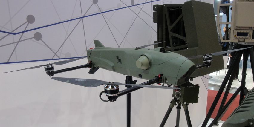
2.2 Small and Very Small (Uninhabited) Aircraft

ROTEM, the WB Group Warmate uses fixed wings (figures 2.1 and 2.2).

Figure 2.1: IAI ROTEM, exact size un-            Figure 2.2: WB Group Warmate, Po-
known (public domain) (Reise Reise,              land (public domain) (VoidWanderer,
2019).                                           2016). Wingspan: 1.4 m (WB Group,
                                                 2019).

2.2 Small and Very Small (Uninhabited) Aircraft
There is no single standard of UA classification. Manufacturers, defence agencies
and civilian organizations all use their own terminologies and classification systems.
Uninhabited aircraft can be classified e.g. by size, mass, maximum flight altitude
and range. A combination of these can be used to define a tier system. Even among
researchers, no consensus exists, thus all terms describing the size or mass of an UA are
always understood in the context of a pre-defined classification system. Comprehensive
overviews of various UA classifications are given in (Hassanalian & Abdelkefi, 2017;
Dalamagkidis, 2015).
   Our classification system is based only on the size of the aircraft. The size is defined
by the length, wingspan or rotor diameter of the aircraft. For multicopters this means
the diameter over all rotors. We define every aircraft below a size of 2 m as small, and
below 0.2 m as very small (table 2.1). We choose these limits because aircraft of this
size and below are typically much more limited in endurance, range, armament and
payload mass compared to larger aircraft. Often the notion of MAV is used.

            Table 2.1: Definitions of ‘small’ and ‘very small’ sizes of UAs.
            Defining property                        ‘Small’                ‘Very small’
 Aircraft   Wingspan, rotor diameter and length ≤ 2 m and > 0.2 m           ≤ 0.2 m

                                           10
3 Aerodynamics
Conditions of flight change as aircraft size decreases. For some understanding, this
chapter gives an elementary introduction into aerodynamics (for an in-depth introduc-
tion, see (Anderson, 1999) and (McCormick, 1979)). Non-technical readers may skip
it.
If some body moves through air – or, equivalently, if air flows in the opposite direction
toward and around the body – the body experiences a force. In case of level flight at
constant velocity (figure 3.1), the lift force L points vertically upward and is equal and
opposite to the weight force W of the aircraft. The drag force D points backward; in
order to prevent its slowing down the movement, an equal and opposite thrust force T
is needed that points in the forward direction – it is provided e.g. by a propeller or a jet
engine. If lift and weight do not balance, the aircraft climbs or descends. If thrust is not
equal to drag, the aircraft accelerates or decelerates.
Figure 3.1: Balance of forces for level flight at constant velocity: The lift force L has to
compensate the weight force W , the thrust force T has to compensate the drag force D.
If the force is referred to an axis of rotation, a moment exists around that axis (figure 3.2).
Figure 3.2: Resultant aerodynamic force R and moment M on the body. V∞ is the
freestream velocity.
For flight the most relevant body is the wing. The resultant force on the wing R
is the sum of the partial forces exerted on all parts of the total wing surface, and
similarly for the total moment M. Due to the wing form and the angle between the air
flow and the wing, usually overpressure develops at the bottom side of the wing and
113 Aerodynamics
underpressure at the upper side. Thus the force R contains a component orthogonal to
the velocity through the air, the lift L. The air flow against the wing induces friction that
exerts a force opposite to the air flow, the drag D. The free-stream velocity V∞ holds
at large distance from the wing (close to the wing, the velocity varies in magnitude
and direction). Figure 3.3 shows the splitting of the resultant force R into the lift L
perpendicular to V∞ and the drag D parallel to V∞ . L and D depend on the angle of
attack α between the chord c, that is the line connecting the extreme points of the wing
profile, and V∞ .
Figure 3.3: Resulting aerodynamic force R split into its components L perpendicular
to the freestream velocity V∞ and D parallel to it. The angle of attack α is measured
between the freestream velocity and the chord c of the wing.
Both forces scale linearly with the area S of the wing projection and the so-called
dynamic pressure q∞ which is one half of the air density ρ∞ times the free-stream
velocity V∞ squared. The dimensionless proportionality constants are the lift coefficient
CL and the drag coefficient CD , respectively. Thus
L = q∞ SCL , (3.1)
D = q∞ SCD , (3.2)
with the dynamic pressure q∞ :
1
q∞ = ρ∞V∞2 , (3.3)
2
and ρ∞ is the density of the freestream far ahead of the body. S is the reference wing
area defined as the planform area of the main wing including the area of the wing
extended through the fuselage (figure 3.4).
123 Aerodynamics
Figure 3.4: Aircraft fuselage (dashed line) and reference wing area S in red.
The coefficients CL and CD are functions of the angle of attack α, the freestream
velocity (figures 3.5a and 3.5b) and the Reynolds number. CL at first increases with
angle of attack α, but beyond a critical angle the flow separates from the upper wing
surface, severely reducing the underpressure there and thus the lift – the aircraft stalls.
CD increases with the angle of attack. The lift and drag characteristics are highly
dependent on the shape of the airfoil, the Mach number and the Reynolds number.
For very high velocities the lift and drag coefficients are no longer constant, but are
functions of the Mach number M, that is defined as the ratio of the body’s velocity to
the speed of sound a:
V∞
M= . (3.4)
a
The other extreme is more relevant in the present context. For very low velocity
and/or small wings, lift and drag are functions of the Reynolds number Re. This number
is given by
ρ∞V∞ c
Re = , (3.5)
µ
where c is the length of the wing chord (figure 3.3) and µ is the dynamic viscosity of
the air, causing friction when moving past the wing.
The Reynolds number is a key parameter that represents the influence of inertial
versus viscous forces. Due to their size, very small UAs operate in a Reynolds number
regime much lower than habited aircraft. We give an example and calculate the Reynolds
number of a typical passenger jet, assuming a mean aerodynamic chord of 4.0 m, a
flight altitude of 9000 m and a cruise speed of 250 m/s. At an altitude of 9000 m, and
133 Aerodynamics
assuming an air temperature of −45 °C, the air density ρ and the viscosity µ are:1
ρ = 0.469 kg/m3 , µ = 1.497 × 10⁻⁵ Pa s. (3.6)
Inserting all values into equation (3.5) yields:
Re ≈ 3.1 × 10⁷ . (3.7)
In contrast, a much smaller aircraft with a chord length of 5.5 cm flying at the same
altitude with a flight velocity of 30 m/s yields
Resmall ≈ 5.2 × 10⁴ , (3.8)
which is three orders of magnitude below the previous results. However, small UAs
typically fly only several hundred metres above ground level (AGL). Assuming flight at
ground level and a temperature of 23 °C, the air density and viscosity values increase to
ρGL = 1.192 kg/m3 , µGL = 1.852 × 10⁻⁵ Pa s, (3.9)
and the Reynolds number decreases to
Resmall,GL ≈ 4.2 × 10⁴ . (3.10)
Figures 3.5a and 3.5b show the lift and drag coefficients c` and cd versus the angle of
attack α for Reynolds numbers 3 × 10⁷ and 5 × 10⁴ for a NACA 2411 airfoil (figure 3.6).
The lower case notation of the coefficients indicates that calculations are valid only for
a purely two-dimensional shape (of theoretically infinite span) such as an airfoil.
Figure 3.5c shows the ratio c` /cd ; in general, a decrease of the Reynolds number
leads to a substantial reduction in the lift to drag ratio L/D. Note however, that airfoils
are designed to operate in certain Reynolds number regimes, and that the NACA 2411
airfoil is not optimized to operate in low-Reynolds-number regimes. The lift-to-drag
ratio L/D is used as a measure of aerodynamic efficiency and creating lift efficiently
means generating as little drag as possible (Anderson, 1999, p. 105).
From figure 3.5c, we see that the maximum ratios are 164 at Re = 3 × 10⁷ and 34
at Re = 5 × 10⁴ . However, these values only hold for wings with infinite span. Finite
wings suffer from additional drag due to strong vortices produced at the wing tips.
Furthermore, a complete aircraft shows more drag components, they stem from the
fuselage and the tail, plus other parts in the air stream. As a consequence, the maximum
lift-to-drag ratio is 13-16 for (normal-size) propeller aircraft, 17-20 for jet airliners
(Loftin, 1985, chs. 6, 13). Typically the ratio decreases with size, very small UAVs may
have ratios in the range of small birds and insects, i.e. below 10 (Mueller, 1999), e.g.
6 for the Black Widow (wingspan: 15.2 cm) (Grasmeyer & Keennon, 2001, table 5, p.
524).
1 ρ and µ were calculated using the AeroToolbox Standard Atmosphere Calculator (AeroToolbox,
2020).
143 Aerodynamics
Furthermore, small flyers are highly susceptible to environmental effects due to their
low mass and slower flight speed. These challenges are typically overcome by using
flapping wings and wing-tail coordination (Shyy et al., 2013, p. 40). Also, airfoil
profiles that optimize aerodynamic behaviour for a specific Reynolds number regime
are used.
2 0.10
Re = 3e7
0.08 Re = 5e4
1
0.06
0
cd
c
0.04
1 Re = 3e7 0.02
Re = 5e4
2 0.00
-5.0° 0.0° 5.0° 10.0° 15.0° 20.0° -5.0° 0.0° 5.0° 10.0° 15.0° 20.0°
(a) Typical dependence of lift coefficient c` (b) Typical dependence of drag coefficient cd
with angle of attack α. C` decreases beyond with angle of attack α.
a critical angle.
100
c / cd
0
Re = 3e7
100 Re = 5e4
-5.0° 0.0° 5.0° 10.0° 15.0° 20.0°
(c) Ratio c` /cd , or ratio of lift L over drag D,
versus angle of attack α.
Figure 3.5: Two-dimensional lift and drag coefficients dependent on the angle of attack
α of a NACA 2411 airfoil (shown in figure 3.6) calculated with XFOIL 6.99 (Drela,
2013) at M = 0 for Reynolds numbers of Re = 3 × 10⁷ and 5 × 10⁴ .
153 Aerodynamics
0.05
0.00
0.0 0.2 0.4 0.6 0.8 1.0
Figure 3.6: NACA 2411 airfoil generated with XFOIL 6.99 (Drela, 2013). The lengths
are normalized relative to the chord.
Aircraft with fixed/variable-geometry wings have to move with a certain velocity to
stay airborne. Their direction of movement usually is controlled by control flaps (small
additional wings) that by aerodynamic forces create a moment around the vertical axis
(rudder) or a horizontal axis in wing direction (elevator). The velocity, climbing or
descent can be controlled by varying the engine thrust.
In rotary-wing aircraft, the above considerations about lift and drag apply to each
individual blade of the rotor(s). Because the velocity through the air increases along
the blade, the blade is twisted to keep the lift distribution approximately constant. The
blade pitch can be varied during one rotation; in case of one main rotor, if the blade
pitch is increased when the blades are in the backward half circle, the craft is tilted
up at the back and some component of the total rotor force points forward, creating
forward thrust. In order to compensate for the torque, often a small tail rotor is used.
Since multiple rotors can counter-rotate, no special counter-torque mechanism is needed.
Tilting the craft in some direction for thrust does not need varying the blade pitch during
rotation, but can be achieved by varying the rotation rates among the rotors.
164 Technical Overview
4.1 Airframe Configurations
In general aircraft are divided into three categories (Austin, 2010, ch. 3.5):
1. horizontal take-off and landing (HTOL),
2. vertical take-off and landing (VTOL),
3. HTOL / VTOL hybrids.
The acronym HTOL designates aircraft which require a horizontal acceleration to
achieve flight speed. HTOL aircraft are typically in fixed-wing configuration, while
VTOL aircraft use rotary or flapping wings. The range of airframe configurations for
UAs is the same as for crewed aircraft. Most common for small UAVs are fixed- and
rotary-wing configurations. Very small UAVs typically use flapping wings.
4.1.1 Fixed-wing Configurations
The three fundamental types of fixed-wing aircraft are the ‘tailplane aft’, the ‘tailplane
forward’ and the ‘tailless’ configuration. Almost all UAs in our database use a pusher-
propeller configuration with the power-plant at the rear of the fuselage. This allows
payload placement in front of the aircraft and an unobstructed forward view. Payload
placement in front of the engine also prevents contamination of the payload with leaked
fluids from the forward engine exhaust (Gundlach, 2012, p. 134). A typical example is
shown in figure 4.1.
From an aerodynamic viewpoint, if a propeller is used, the induced air velocity of
the rear-mounted propeller does not increase the friction drag of the fuselage as much
as the slipstream would from a front-mounted tractor propeller (Austin, 2010, p. 34).
However, tractor propellers have clean airflow to the propeller, which leads to higher
propeller efficiency (Gundlach, 2012, p. 134). Gundlach adds that tractors can also be
quieter because there is no wake impingement upon the propeller and that tractors allow
a large tail moment arm due to the forward engine location.
Flying-wing (including delta-wing) aircraft are tailless and suffer from a reduced
effective tail arm in both pitch and yaw axes,1 although the rearward sweep of the
wing adds to directional stability (Austin, 2010, p. 36). An argument in favour of
the flying-wing configuration is that the removal of the horizontal stabiliser avoids the
additional profile drag due to that surface. However, the poorer lift distribution of the
flying wing can result in negative lift at the tip sections and result in high induced drag
(Austin, 2010, p. 36). An example of a flying-wing UAV is the Spaitech Sparrow shown
in figure 4.2.
1 An aircraft in flight can rotate around three axes with their origins at the centre of gravity. The pitch
axis is parallel to the wings of a winged aircraft, the roll axis is drawn through the aircraft’s body
from tail to nose in forward direction, and the yaw axis is directed towards the bottom of the aircraft,
perpendicular to the other two axes.
174.1 Airframe Configurations
Figure 4.1: Conventional fixed-wing Figure 4.2: Flying wing with tractor
configuration: IAI GreenDragon ((C) propeller: Spaitech Sparrow. Wing-
IAI, reprinted by permission) (IAI, span: 0.98 m ((C) Spaitech, reprinted
2019a). Wingspan: 1.7 m (IAI, 2019b). by permission) (Spaitech, 2019).
Another typical form is the tandem-wing configuration. It uses two wings of similar
areas with one at the front and one in the back of the aircraft. The advantage is that in
case of wing folding along the fuselage, for the same total wing area the stowage space
is reduced. The maximum wingspan is then twice the fuselage length. However, the
forward wing produces a downwash field on the rear wing, leading to a higher induced
drag, so that tandem-wing configurations usually have lower aerodynamic efficiency
than conventional configurations (Gundlach, 2012, p. 118). Tandem-wing UAVs can
easily be deployed from the stowed state, typically from tube launchers, and unfold
their wings after launch (figure 4.11). An example is the Raytheon Coyote shown in
figure 4.3.
Figure 4.3: Tandem-wing configura- Figure 4.4: Custom wing configura-
tion: Raytheon Coyote (public domain, tion: UVision HERO-30 (public do-
cropped) (NOAA, 2016). Wingspan: main, cropped) (Swadim, 2019). Exact
1.47 m (Streetly & Bernadi, 2018). size unknown.
An alternative to increase the wing area while still allowing a folding mechanism
is to use four primary and four secondary wings as shown on the UVision Hero-30
184.1 Airframe Configurations
(figure 4.4). This design allows a shorter fuselage length compared to a tandem-wing
configuration while maintaining a large wing area.
Advantages of HTOL UAs are typically a higher endurance compared to rotary-wing
aircraft, while they lack the manoeuvrability and VTOL ability of rotorcraft. A major
disadvantage is the reliance on an extended space to launch and land and the necessity
for constant forward movement to stay airborne.
4.1.2 Rotary-wing Configurations
Rotary-wing aircraft or rotorcraft use one or more main rotors to generate lift (figure 4.5).
Designs using multiple rotors are called multi-rotors, or e.g. tri- or quadrotors (-copters)
indicating the number of rotors used. In case of multiple rotors, their blades are fixed in
pitch and horizontal thrust is generated by changing the speed of rotation of each rotor,
tilting the craft in the intended direction. An example of a quadrotor is the Bitcraze
Crazyflie (figure 4.6).
Their main advantage over fixed-wing aircraft is their VTOL capability, allowing
them to access spaces unavailable to fixed-wing aircraft. Moreover their ability to
hover allows them to remain stationary which simplifies surveillance, even allowing
them to land during a mission to save fuel or battery capacity. Compared to fixed-wing
aircraft, no additional equipment such as airbags or a parachute is required for recovery.
However, rotary-wing aircraft usually have a lower endurance (Gundlach, 2012, pp.
47–50), a lower cruise speed and thus longer response time, and achieve lower altitudes
(Austin, 2010, p. 181), which makes them more suitable for short ranges.
Figure 4.5: Helicopter configuration: Figure 4.6: Quadrotor Bitcraze Crazy-
AeroVironment VAPOR35. Rotor dia- flie 2.1. Width (motor-to-motor and
meter: 1.7 m ((C) AeroVironment, re- including motor mount feet): 9.2 cm
printed by permission) (AeroViron- ((C) Bitcraze, reprinted by permission)
ment, 2019). (Bitcraze, 2020).
194.1 Airframe Configurations
4.1.3 Hybrid Configurations
Hybrid configurations intend to combine the capabilities of both HTOL and VTOL
aircraft. In the tilt-rotor configuration, rotors are mounted onto the front tip of the main
wing and can be rotated forward by 90° to act as propellers for cruise flight (figure 4.7).
An special combination of a tri- and tiltrotor is the Skyborne Technologies Cerberus
with one rotor at its tail and two main lift fans at the front that can tilt forward (Skyborne
Technologies, 2019).
Figure 4.7: Tilt-rotor configuration during cruise and hover flight.
4.1.4 Flapping Wings
Flapping-wing aerial vehicles use their wings to generate thrust in addition to lift. Flap-
ping wings can significantly increase the manoeuvrability of an aircraft. A combination
of flapping motion, wing deformation, body contour and tail adjustment allows a precise
trajectory control at high speeds (Shyy et al., 2013, p. 7). Flapping wings are used
almost always by UAVs of very small sizes.
Current very small flapping-wing UAVs face the challenge of relatively high design
complexity, low endurance and low payload mass.
Figure 4.8: DelFly Nimble. Wingspan: Figure 4.9: DelFly Micro. Wingspan:
33 cm (public domain) (MAVLab TU 10 cm (public domain) (de Wagter,
Delft, 2018; de Croon et al., 2016). 2008; de Croon et al., 2016).
204.2 Materials and Manufacturing
We divide flapping-wing UAVs into the tailless and ‘with tail’ categories, since the
former are less conventional as the tail is typically used as an important control structure.
Tailless flapping-wing UAVs have to use the same wings for lift generation as well as
control. An example of a tailless design is the DelFly Nimble (mass: 29 g) (figure 4.8)
as well as the Nano Hummingbird (figure 5.1) (mass: 19.0 g). A design with tail is the
DelFly Micro (mass: 3.07 g) (figure 4.9).
4.1.5 Tethering
Tethered UAVs are VTOL aircraft connected to a power-supply ground unit. Their radius
of action is limited for a stationary ground unit, but is much larger if the power supply is
transported on a ground vehicle. For example, the HoverMast 100 can reach an altitude
of 100 m (SCR, 2019) and operate along a moving pick-up truck (figure 4.13 below).
As long as a steady power supply is ensured, tethered configurations offer basically
limitless flight time until maintenance is required. Since the on-board battery can be
much smaller and lighter compared to non-tethered rotary-wing aircraft, the remaining
aircraft components can be much heavier, increasing overall aircraft performance.
Tethered UAVs are typically used for surveillance missions such as border control or
for guarding infrastructure.
However, a UA might simply be tethered because it would not fly or achieve a certain
flight performance with the increased weight of an on-board power supply unit. An
example is the research system RoboBee, which would otherwise not achieve flight due
to its extremely small size (mass: 80 mg) (Ma et al., 2013).
4.2 Materials and Manufacturing
Small UAs developed by professional institutions tend to use modern materials and
manufacturing methods (Gundlach, 2012, sec. 7.3). Various types of plastics, foam
and sandwich structures are used, metal only for special parts. Composite materials
provide high strength at low weight; the load is borne by fibres, sometimes woven,
often with plies of unidirectional fibre sheets in different directions. Fibres of graphite
(carbon) provide higher strength than fibres of glass or aramid. They are supported and
bonded together by a matrix material, sometimes thermoplastic, often a resin such as
epoxy that polymerises. With two components this happens at normal temperature; for
higher requirements a thermoset resin is used that has to be cured at high temperature.
Consolidation and better fit to a mould can be supported by pressure, often from the air
by a vacuum under an airtight film. Wings and fuselages can be made with integrated
ribs and from fewer pieces, requiring fewer fasteners. Tapered wings and rounded
shapes can be made easily.
Additive manufacturing (often called 3-D printing) provides much more flexibility,
moulds are not needed and complex forms, e.g. with inner cavities, can be produced.
Several methods and materials can be used to print parts or complete structures (Goh
214.3 Power and Propulsion
et al., 2017). Beside wings and fuselages mechanical parts have been made, e.g. in
gears.
In very lightweight UAs, special work has been done to produce the flapping wings,
often emulating insect wings. Various methods have been described how stiffeners,
membranes and links can be made and bonded, e.g. by laser cutting (Liu et al., 2017)
or microsystems technology (also called microelectromechanical systems (MEMS)
technology) (Bao et al., 2011); carbon nanotubes have been added for strength (Kumar
et al., 2019). For driving, beside electrical motors with transmissions, ‘artificial muscles’
are made from piezoelectric materials, dielectric or electrostatic elastomers (Chen &
Zhang, 2019).
A special concept can make manufacture easier and allow series production, poten-
tially at low cost: producing structures in two dimensions and then folding them up,
creating a three-dimensional object, as in Japanese paper folding (origami) (Sreetharan
et al., 2012; Dufour et al., 2018). Laser cutting, lamination and microsystems techno-
logy have been used; the latter can produce integrated electronic circuits in the same
process. Rigid and flexible materials have been combined for movable elements. Actu-
ation for moving elements out of the plane can use shape-memory materials, flapping
wings can be driven by piezoelectric or dielectric elastomers. Used for mass production
such methods may enable swarms of immense numbers of disposable MAVs.
4.3 Power and Propulsion
The vast majority (89 %) of the 129 UAVs in our database uses electric power, mostly
from batteries; for one type a fuel cell is stated, the few tethered ones receive external
power. For one very small (80 mg) tethered, flapping-wing UAV, RoboBee, an upgraded
version has been equipped with solar cells (RoboBee X-Wing, 259 mg, that can fly as
long as it is under intense light.
The advantage of using electric motors is their low acoustic signature compared
to combustion and jet engines. In addition, depleted batteries may be replaced with
fully charged ones in a few seconds, so-called ‘hotswapping’. Furthermore, the UAV
mass stays constant throughout the flight, unlike with engines that use fuel, simplifying
centre-of-gravity considerations in the initial UAV design phase. The disadvantage of
using batteries is their lower energy density compared to fuel, leading to a shorter flight
time.
Nine UAVs use combustion engines, and two can use either electric or combustion
power. The eleven types with (optional) combustion have maximum take-off masses
of 2.5 to 13 kg, with the exception of the rotary-wing Comandor with 110 kg that is an
outlier in many respects.
There is one type with turbojet propulsion (Futura) with 70 kg mass, also an outlier.
Propulsion is by propeller for all others of the 65 fixed-wing UAVs, for two thirds
in the pusher arrangement (propeller in the back). Two types use tilt-rotors. The
rotary-wing UAVs have one main rotor or several rotors.
224.4 Guidance and Navigation
Flapping wings, with or without tail, are used with very lightweight UAVs only; the
masses of the twelve types lie between 80 mg and 29 g.
4.4 Guidance and Navigation
4.4.1 Navigation and Autopilots
Most small UASs use a global navigation satellite system (GNSS) to determine the
aircraft’s position and to navigate between waypoints. A GNSS consists of a collection
of satellites orbiting the Earth at an altitude of approximately 20 000 km (Austin, 2010,
ch. 11.1). Each satellite transmits radio signals that contain the start time of the signal
and travel at the speed of light. A receiver can then calculate the range to the satellite
by using the arrival time. Determining the exact position in three dimensions, however,
requires signals from four or more satellites. The result is a sequence of discrete
aircraft positions. GNSS signals can be jammed by emitting a radio-frequency signal
strong enough so that the satellite’s signals are outweighed. To avoid the loss of the
aircraft, usually an additional, so-called dead-reckoning system, is used. It uses the
aircraft’s position at the start of the mission and time, speed and direction measurements
to calculate the current position. These calculations can be combined with the data
provided by the GNSS to receive a smoothing between calculated positions and to
continue navigation in case of a GNSS signal loss. Current GNSSs in use are the
US-owned global positioning system (GPS), the Russian global navigation satellite
system (GLONASS), the European Galileo and the Chinese BeiDou navigation satellite
system (BDS).
In addition to jamming, GNSS signals can be spoofed, i.e. the satellite’s transmissions
are mimicked and false location information is fed to the receiver. This can be used
to either completely deny the use of GNSS by feeding obviously wrong information
or by slowly directing the aircraft away from the original route. For these reasons,
navigational systems independent of external inputs, such as an inertial measurement
unit (IMU), may be used. An IMU functions independently of external signals. Using
inertial forces, accelerometers measure the change of the velocity in three dimensions.
To refer these measurement to fixed coordinate directions the rotations of the system are
measured e.g. by gyroscopes. With knowledge of the starting velocity, the acceleration
is integrated over time to yield the changed velocity. With the given start location,
integrating the velocity gives the changed location. IMUs have the disadvantage that
their estimates drift over time. For high-grade accelerometers and gyroscopes the drift
can be low, but for miniaturized systems used by small UAVs which tend to use MEMS
devices that have very high drift and can provide nonsense estimates in seconds or
minutes (Gundlach, 2012, p. 392).
An IMU and GNSS system can be combined to an inertial navigation system (INS),
where the IMU provides state estimates at a high rate, while the GNSS provides discrete
positions at a lower rate, allowing for correction of the IMU drift.
Inertial measurement systems are sometimes complemented with magnetic-field
234.5 Launch and Recovery
sensors for orientation in the earth magnetic field and barometric sensors for alti-
tude. Autopilots − systems for controlling the trajectory of aircraft, often including
waypoint-navigation − can integrate such systems. Miniaturization in particular of
microelectromechanical sensors has been advanced greatly by their introduction in
every-day electronics such as smart phones. One exemplary device with three-axis
accelerometer, three-axis gyroscope and three-axis magnetometer measures 3 × 3 × 3
mm3 with a mass of 0.14 g (TDK, 2021). University researchers have built autopilots
of extremely small size and extremely light weight. One example including telemetry
and remote control had 2.8 g mass on a 2 × 2 cm2 board (Remes et al., 2014), another
had 1.3 g including communication (Runco et al., 2019).
A different method of navigation uses optical flow, that is the apparent motion of
(parts of) a camera image as the camera moves and/or changes its view angles. This
motion can be derived from the time sequence of the pictures, e.g. by identifying
landmarks or by image correlation. In order to provide coordinates in an external
reference system, additional information is needed, e.g. the UAV attitude and its
altitude. In particular for small UAVs, optical flow can be combined with IMUs and an
altimeter (e.g. Santamaria-Navarro et al., 2018).
4.4.2 Control Stations
The control station is a human-machine interface allowing communication with the
UAV as well as its control. The control station may be based aboard ships or aboard
another aircraft (‘mothership’) or based on the ground. Almost all small and very small
UAVs in our database use a ground control system (GCS). GCSs typically consist of
ruggedized laptops or tablets, displaying the UAV’s attitude, altitude, airspeed and
position or video and camera feed from the payloads. Remote controls with joysticks
and switches may be included for manual control.
Using the GCS the UAV’s flight path can either be directly controlled, e.g. by using a
remote control and video feed, or by using a pre-progammed waypoint system that may
also be updated during flight. The UAV may also have on-board programs that allow
it to execute tasks without operator control, such as orbiting at a given speed, radius
and altitude for loitering (e.g. WB Group, 2019) or returning home automatically (IAI,
2020). These in-built functions lower the number of direct inputs necessary for flight
and thus reduce pilot workload.
4.5 Launch and Recovery
Launch methods include hand-launching the vehicle by throwing it forward, launch
from a catapult via e.g. a bungee rope, from a pneumatic tube (figure 4.10), multiple
tube launchers in quick succession (figure 4.11) or a grenade launcher (figure 4.12b).
244.5 Launch and Recovery
Figure 4.10: AeroVironment Figure 4.11: Raytheon Coyote launched
Switchblade (AeroVironment, 2021b) from low-cost UAV swarming techno-
((C) AeroVironment, reprinted by logy (LOCUST) launcher (public do-
permission). main, cropped) (Smalley, 2015).
A hand launch can influence the UA configuration to avoid injury of the person throwing
the UAV (Gundlach, 2012, p. 442). Tube launchers can be very compact and prepared
in a short amount of time. However, they can only be used with UAVs that can unfold
their wings and propeller after deployment. The UAVs launched from tubes usually
have a pusher propeller at the back of the aircraft, that has a small shield protecting it
from the launch and which is lost after launch (figure 4.11).
Launches from aircraft are also possible, allowing a transport of the UAVs close to
the mission area, thus increasing their mission range. An example is the Perdix UAV
deployment from a F/A-18 Super Hornet fighter jet (figure 4.14). The Perdix UAVs use
containers similar in size to flare canisters so that the flare ejection mechanism already
available on the aircraft can be used for a UAV launch instead. An aircraft can also be
used as a mothership with an aircraft recovery function as in the Defense Advanced
Research Projects Agency (DARPA) Gremlins project ( figure 4.15). The ability to
recover UAVs removes the necessity for ground landings or UAV loss after a completed
mission.
Launch from ground vehicles, such as the autonomous Rheinmetall Mission Master
(Monroy, 2019), is also possible. UAVs can also be tethered to a moving ground vehicle
such as the SkySapience HoverMast (figure 4.13).
254.5 Launch and Recovery
(a) After launch, the rotor arms extract and (b) Drone-40 inserted into M320 40 mm
the UAV acts as a quadcopter. grenade launcher.
Figure 4.12: DefendTex Drone-40 rotary-wing UAV with integrated warhead, launched
from a hand-held 40 mm grenade launcher (US DoD photos, public domain) (Soldier
Systems, 2019).
Figure 4.13: Sky Sapience HoverMast tethered to power supply unit transported on a
pick-up truck ((C) SkySapience, reprinted by permission) (Sky Sapience, 2020).
The conventional landing with a landing gear with wheels and a (small) airstrip is
rare for small and very small fixed-wing aircraft. They usually come without a landing
gear due to weight and volume limitations, but also because it is not needed. They
are so lightweight that simpler mechanisms can be used, such as a deep-stall or belly
landing.
During a deep-stall landing, the aircraft flies at a low altitude and its nose is pulled
up to induce a stall, so that the aircraft falls onto the ground.
A skid or belly landing is only applicable to UAV rugged enough to survive the
264.6 Payloads
landing or cheap enough as to be considered expendable.
In other cases where these simpler methods are not viable, a parachute or an airbag
may be used instead. The airbag acts as an energy absorbing system that reduces the
severity of ground impact. Both the parachute and the airbag have the disadvantage of
adding to the overall weight and taking additional space inside the aircraft.
Another option is a guided flight into a net, by which the UAV is captured and stopped
mid-air. However, the net has to be placed on the ground beforehand, thus limiting the
landing location to a specific area.
Figure 4.14: Swarm deployment from Figure 4.15: DARPA Gremlins pro-
three F/A-18 Super Hornets in October ject (artist’s concept, public domain)
2016 (public domain) (TIME, 2018). (DARPA, 2018).
4.6 Payloads
Austin defines payload as the part of an aircraft specifically carried to achieve a mission
or to fulfil a certain role. The aircraft should be capable of flight with the payload
removed (Austin, 2010, ch. 8, p. 127). The mission requirements determine the optimal
configuration of payload and aircraft to perform a specific role.
Payloads can be divided into two basic categories:
1. sensors, cameras, weapons, etc. which remain attached to the aircraft,
2. dispensable loads such as missiles, bombs, fluids, etc.
In the following, we give a brief overview of the sensor and offensive payloads found
in the UAV database.
4.6.1 Sensor Payloads
Payloads meant for intelligence, surveillance and reconnaissance (ISR) purposes are
mainly cameras with variable viewing direction. They contain both electro-optical (EO)
and infrared (IR) sensors.
EO sensors operate in the visible (wavelength 0.4 µm to 0.8 µm) or near-infrared
(NIR) band, ranging from 0.7 µm to 1.0 µm (Gundlach, 2012, p. 519). Usually the
output is colour video if the camera records in the visible band, or greyscale for increased
contrast and for low light (Gundlach, 2012, p. 558). Usually there are zoom capabilities.
274.6 Payloads
IR sensors typically operate in three different wavelength bands: short-wave infrared
(SWIR) ranging between 1 µm to 1.7 µm, midwave infrared (MWIR) ranging between
3 µm to 6 µm and long-wave infrared (LWIR) ranging between 6 µm to 14 µm (Gundlach,
2012, p. 520). SWIR sensors have good resolution in low light conditions and do not
require cooling, but are not thermal imagers like MWIR and LWIR sensors. Their
detection relies on energy reflected by the object. MWIR sensors can detect both
reflected and emitted energy, while LWIR sensors primarily detect energy emitted by
the object, making them especially useful to detect heat signatures.
EO and IR sensor systems are usually combined to so-called EO/IR balls. These
may additionally include laser illuminators, designators and rangefinders (Gundlach,
2012, p. 557). A laser illuminator illuminates a target in the band of the night-vision
sensor, which may be seen by the EO/IR ball or external night-vision equipment. Laser
designators are used to point towards targets in the wavelength band of the detector,
similar to laser pointers but not necessarily in a visible band.
EO payloads are usually mounted in two ways:
1. Forward looking from a mounting in the nose, with the sensors mounted on
gimbals with actuators. The range can be upwards and forwards to above the
horizon or upwards and rearwards. Capabilities for a pan in azimuth and image
stabilisation may be present (Austin, 2010, p. 132).
2. A rotatable turret mounted beneath the aircraft to cover a 360° azimuth field of
view, with sensors, elevation and roll gimbals and their actuators (Austin, 2010, p.
132) (e.g. as seen in figures 4.1 and 4.2).
Positioning the EO/IR ball below or in front of the aircraft provides an unobstructed
view. Internal payloads, in contrast to external ones such as turrets, reduce aerodynamic
drag and thus increase the aircraft’s endurance, range and speed. A gimbal allows an
independent movement of the payload, the simplest are able to pan and tilt while more
advanced gimbals may include inertial stabilisation to mitigate effects of manoeuvring,
vibration and air turbulence (Friese et al., 2016).
Further non-standard non-weapon payloads used by small and very small UAs as
listed in our database are:
• gas (Streetly & Bernadi, 2018, pp. 59-60) and fire detector (IAI, 2020),
• radiological detector (Streetly & Bernadi, 2018, pp. 124-125), spectrometer
(Streetly & Bernadi, 2018, pp. 59-60), dosimeter (Spaitech, 2019),
• communications intelligence (COMINT) equipment (IAI, 2020),
• radar (Sky Sapience, 2019); (Streetly & Bernadi, 2018, pp. 216–217),
• light detection and ranging (LiDAR) (AeroVironment, 2019),
• (radio) relay (Sky Sapience, 2019); (Streetly & Bernadi, 2018, pp. 278-280),
• hyperspectral sensor (AeroVironment, 2019).
4.6.2 Offensive Payloads
Offensive payloads for small UAs include lethal and non-lethal weapons. The UA may
function as a either a weapons platform or as a guided weapon itself. A list of lethal
284.6 Payloads
weapons and UAV types they are carried by is given in table 4.1 (see also section 8.3).
Most prominent are warheads integrated into the aircraft’s fuselage. The UAV then
acts similar to a missile or guided munition and is destroyed by the warhead’s detonation.
These are usually designed to work against specific targets, such as fragmentation or
anti-personnel warheads, e.g. the Polish Warmate (WB Group, 2019), anti-tank (Israeli
Green Dragon (IAI, 2019b)) or a high-explosive charge (Australian Drone-40 (N.,
2019)).
Lethal weapons not destroying the aircraft during the attack are a rocket-propelled
grenade launcher, a 40 mm grenade launcher or free-falling bombs ejected from the
UAV.
Small UAVs armed with missiles or precision-guided munitions do not appear to have
been developed yet. The manufacturers of the Comandor and Cerberus mention the
possibility of using missiles (table 4.1, but have not shown or mentioned any existing
missile to be used.
Non-lethal weapons used are an (anti-UAV) net launcher (Delft Dynamics BV, 2016),
a kinetic anti-UAV tip (Soldier Systems, 2019), as well as smoke grenades (Soldier
Systems, 2019) and tear gas released from a canister mounted under the UAV (ISPRA,
2019).
Table 4.1: Offensive payloads and UAV types using them. Some types can use a variety
of weapons and are thus listed multiple times. The most prominent armament is an
integrated warhead, with a total of 20 UAV types. For references, see the UAV database
in appendix A.
Armament Types
Integrated warhead Alpagu, Alpagu Block II, CH-901, Coyote, Demon,
Drone-40, Futura, Green Dragon, HERO-20,
HERO-30, HERO-70, KYB-UAV, Kargu, ROTEM,
Spike Firefly, Switchblade, Warmate, Warmate TL,
Warmate V, ZALA LANCET-1
Shotgun Cerberus
40 mm grenade launcher Cerberus
Rocket-propelled grenade (RPG) Demon
Bombs Comandor
Missile Comandor, Cerberus
29You can also read