SWITCHING FROM SKETCHUP TO VECTORWORKS - Amazon S3
←
→
Page content transcription
If your browser does not render page correctly, please read the page content below
SWITCHING FROM SKETCHUP
TO VECTORWORKS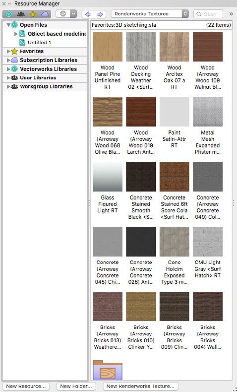
INTRODUCTION
There are a lot of 3D modeling software programs to choose from and each has its own
strengths and weaknesses. For architects, flexibility and ease of use are necessary to foster
the creative process, yet precision and depth are required for accuracy. Many architects use
several different programs throughout the life of a project; some to model ideas and others to
create drawings. Some Architects use SketchUp™ to create 3D forms and then import those
geometries into another program, like Vectorworks®, to extract views for technical drawings
or to add data. This process is inefficient, adding unnecessary time and effort into reworking
and redesigning when designs change. It also creates opportunities for transfer errors.

HOW ARE SKETCHUP
AND VECTORWORKS DIFFERENT?
SketchUp uses a combination of vector, planar, and mesh surface modeling technology.
This technology is good for general idea generation and exploration. Vectorworks Architect
includes robust BIM and 2D documentation capabilities, as well as extensive 3D modeling
capabilities. These capabilities include true solids modeling, NURBS surfaces, and vector,
planar, and mesh modeling that can be used for schematic exploration, as well as the
creation of accurate and detailed models and drawings. Vectorworks Architect can also
be used to create sketch-stylized renderings and photorealistic renderings. And because
this is all done with the same model in the same application, Vectorworks makes the
design process more efficient, giving you to time to focus on refining your ideas.

Although modeling in Vectorworks may appear to be different than SketchUp, it has similar
capabilities, as well as additional modeling capabilities that are not found in SketchUp.

 MODELING CAPABILITIES                          SKETCHUP     VECTORWORKS

 Mesh surface                                       •               •
 Booleans                                                           •
 Arrays                                                             •
 Extrusions, lofts, and shells                                      •
 NURBS                                                              •
 Walls, slabs, and roofs                                            •
 Parametric BIM objects                                             •
 Parametric site modeling objects                                   •

                                                                                      VECTORWORKS.NET   2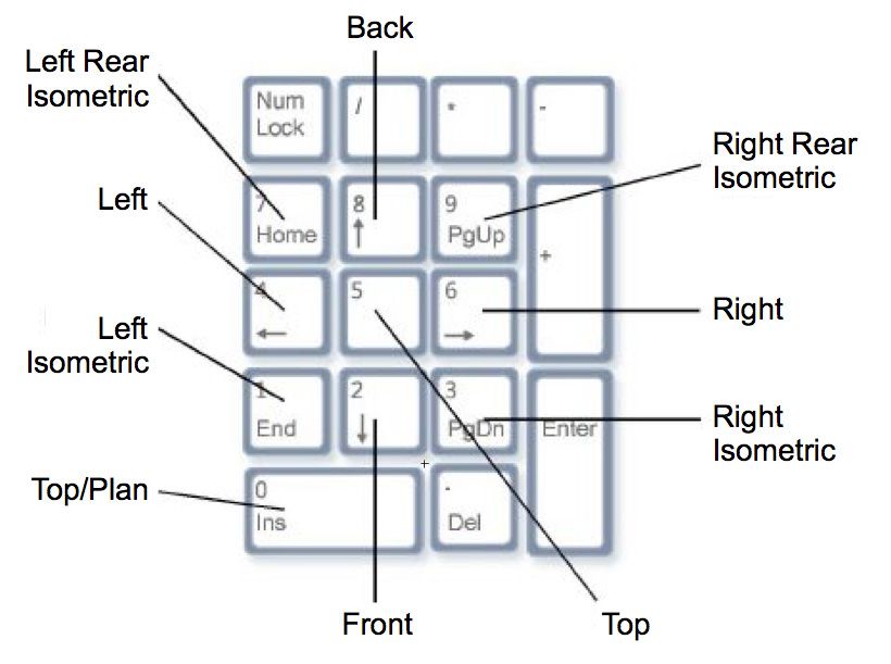
CAN I USE SKETCHUP WITH VECTORWORKS?
    Yes. Vectorworks software has the broadest set of import/export capabilities available
    in any BIM software, including direct import of SketchUp .skp files. When SketchUp files
    are imported into Vectorworks, the surface models and their associated textures are all
    transferred into the application as Renderworks® textures. This means that rendering
    textures created and applied in SketchUp are also available in Vectorworks.

    Other import options include the ability to translate specific surfaces from a SketchUp model
    into Vectorworks building objects. This means that moving your schematic planar-based model
    from SketchUp to an accurate and intelligent BIM model in Vectorworks requires fewer steps.

    However, the types of geometry you obtain from a SketchUp file limit the fidelity
    of data when exchanging models with other applications. For example, SketchUp
    geometry is imported as mesh or 3D polygons in Vectorworks. This type of
    geometry limits the ability to edit them efficiently in Vectorworks.

    WHY SWITCH FROM SKETCHUP TO VECTORWORKS?
    Unlike SketchUp, Vectorworks Architect provides a flexible modeling environment for design
    exploration in addition to a full-suite of BIM tools for modeling and exchange. Vectorworks Architect
    is one of the best software programs to connect conceptual design to completed BIM models.

    With Vectorworks Architect, communicating your ideas is easy. Vectorworks
    Architects let you create any type of output documentation — from presentation
    drawings with rendering styles of your choice, to beautiful 2D drawings to
    complete your construction documentation — all within one interface.

    Vectorworks Architect includes tools that help you inform your design decision with
    the ability to conduct various types of analysis, such as energy, land use, storm water
    management, sun studies, and site modeling, as well as various types of reporting.

    There are many reasons why an architect may choose to start and end a formal
    exploration process with Vectorworks rather than SketchUp. This includes:

     ∙∙ Object-based modeling                     ∙∙ Attribute control and rendering

     ∙∙ Editing parametrically                    ∙∙ Drawing layout capabilities

     ∙∙ Intelligent objects and reporting         ∙∙ Interoperability

3   Switching from SketchUp to Vectorworks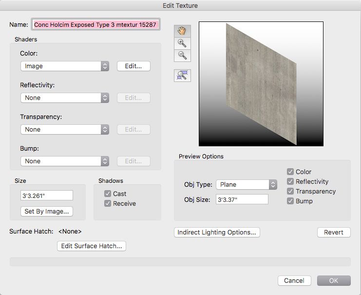
OBJECT-BASED MODELING

FIGURE 1
Example of 2D objects in Vectorworks

Each entity drawn or modeled in Vectorworks is a unique object, from 2D shapes, such
as lines, arcs, rectangles, circles, polylines, or NURBS curves, to 3D objects such as
extrudes, surfaces, NURBS surfaces, subdivisions and hybrid 2D/3D objects like walls,
roofs, doors, windows, hybrid symbols, and many more. This offers far more advanced
capabilities than SketchUp. For example, in SketchUp, a rectangle is composed of
four edges and a face; in Vectorworks a rectangle is a single object with a fill.

In Vectorworks, you can easily compose various complex 2D shapes by combining multiple
objects using 2D Booleans, polylines, and compose functions. Furthermore, when modeling
in Vectorworks, objects retain the elements that were used to create them, so modifying an
object long after it was created is simple. Double-clicking on an object — like an Extrude
Along Path object — allows for editing of either its profile or its path. Groups and symbols
have the same editing behavior; double-clicking on them allows the user to edit any of their
components. In SketchUp, you can group objects, but the history of operations is never retained.

                                                                                     VECTORWORKS.NET   4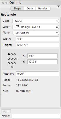
FIGURE 2
    Example of 3D objects operation history

    EDITING PARAMETRICALLY WITH PRECISION AND DYNAMIC CONSTRAINTS

    FIGURE 3
    The Object Info palette

5   Switching from SketchUp to Vectorworks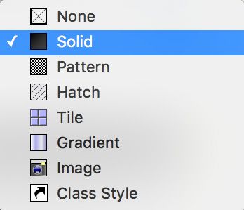
When an object is selected in Vectorworks, its properties are visible in the Object
Info palette, which is similar to the Entity Info window in SketchUp, but what sets
Vectorworks apart is that all of its parameters are editable here. To change the length
of a rectangle, for example, there is no need to invoke a scaling or editing tool; a new
length can simply be typed into the Width parameter in the Object Info palette.

INTELLIGENT OBJECTS

FIGURE 4
Building Shell tool set

“Create Objects from Shape.” is a context menu command that allows the user to
convert generic objects into intelligent objects, like converting polylines to walls and
slabs. These objects can then have relevant data attached to them and have components
and thicknesses specified. Generic modeled objects can also have data attached, or
parametric, data-rich objects can be modeled directly with BIM modeling tools.

Using data-rich objects in Vectorworks allows for far more than just the 3D geometry.
With these objects, you can directly extract multiple types of reports or worksheets to
use as schedules on the drawings or as tools to generate various types of analysis.

                                                                                           VECTORWORKS.NET   6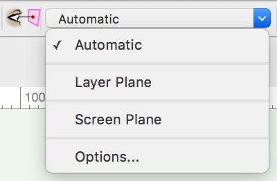
ATTRIBUTE CONTROL AND RENDERING

    FIGURE 5
    Attributes palette

    Vectorworks has a high level of 2D attribute control. Objects can have specific line weights, line
    types, and line colors, as well as specific fill colors, hatches, tiles, gradients, and textures. These
    attributes can be set by object or by class, allowing the user to standardize the drawing outputs.

    FIGURE 6
    OIP Render Tab, Resource Manager and Edit Texture dialog box

7   Switching from SketchUp to Vectorworks
In addition to color attributes of an object in Vectorworks, you can apply high-level textures
with Renderworks texture shaders. Textures can be applied by simply dragging and dropping a
texture from the Resource Manager onto an object. You can select a rendering style from the View
menu > Render Style. Vectorworks uses two types of rendering technology — OpenGL, which
is a fast rendering mode — and Renderworks®, based on Maxon CineRender. To create high-
quality, photorealistic rendering, you can switch to one of the Renderworks modes. Each render
mode has its own set of options, providing a wide range of styles to express many design ideas.
DRAWING LAYOUT
With its full range of 2D tools and graphic options, Vectorworks lets you create beautiful
presentation drawings and 2D construction documentations within the same software.
Using viewports allows the user to customize 3D views and renderings, as well as 2D
drawings, all in the same working environment. With further configurations like class
overrides and data visualization, objects can be given different attributes in different
drawings. Intelligent objects, class attributes, and viewport class overrides allow you to
model objects only once, without needing to duplicate, redraw, or trace over objects to
modify them. Using one program for both modeling and drawing also means that, with
proper file setup, drawings will be automatically updated when the model is changed.
INTEROPERABILITY
With the broadest set of import/export capabilities available in any BIM software, Vectorworks
can communicate with a wide range of tools, allowing for increased collaboration with all
project stakeholders. Vectorworks makes it possible to use a single program to take your
design ideas to a BIM model, communicate and document your vision, and collaborate.
VECTORWORKS.NET 8HOW DO I SWITCH FROM SKETCHUP TO VECTORWORKS?
USER INTERFACE
The Vectorworks default user interface has tool palettes docked on the left side of
the screen and navigation and information palettes on the right side of the screen.
The palettes can be docked or floating, or they can be reordered and docked
together as larger floating palettes. As in SketchUp, you can customize your palette
or create a new one by editing the workspace in the Workspace Editor.
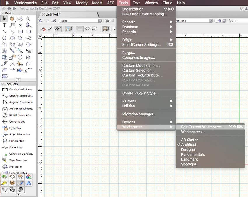
FIGURE 7
Menu path to Workspace Editor
Watch the video
In Vectorworks, there is only one tool or menu command per function, so every tool and
menu command is unique. Using the Workspace Editor, tool icons can be removed from
or added to tool palettes, as well as reordered and/or placed into sub-categories. The
same can be done with menu commands. In addition, tools and menu commands can be
placed in more than one palette and menu respectively, based on a user’s preference.
There are key shortcuts and key aliases. Key shortcuts can
also be customized in the Workspace Editor.
Watch the video
9 Switching from SketchUp to VectorworksA customized workspace has been provided with this document that organizes
tools and menu commands in a way similar to SketchUp user interface.
MODEL ORGANIZATION
Layers in SketchUp are equivalent to classes in Vectorworks. Classes in Vectorworks are
useful for assigning object attributes and “classifying” objects. Like objects assigned
to layers in SketchUp, objects in Vectorworks can be set to have the same color as
their class, as well as line color, line weight, line type, and texture. Layers exist in
Vectorworks, but they are for organizing objects in space. They can be given a vertical
height to orient objects so they can be used as floor heights in architectural design.
Watch the video
TOOLS
Tools in Vectorworks behave in a similar manner to tools in SketchUp. There are single-click and
multi-click tools. Tool prompts appear in the lower left corner of the drawing window in SketchUp,
while in Vectorworks they appear in the Tool bar, in the upper left corner of the drawing window.
In Vectorworks, double-clicking exits out of continuous tools like the Polyline tool. Tools also
remain selected after completion and will remain selected until a new tool is clicked, a keyboard
shortcut is typed, or a blank area of the drawing is double-clicked. The keyboard shortcut for
each tool displays when you mouse over the tool icon. The tool tip displays the name of the
tool and the keyboard shortcut in parentheses. As mentioned earlier, keyboard shortcuts can
be modified from the menu: Tools > Workspaces > Workspaces > Edit Current Workspace.
Watch the video
FIGURE 8
The Tool bar
VECTORWORKS.NET 10In Vectorworks, instead of separate commands for tool variations, there are tool modes.
When a tool such as the Arc tool is selected, its different modes display in the Tool bar. Each
mode has a different icon. Some tools have different levels of modes, either for different
aspects of the tool or different sub-modes, but they are all visible across the Tool bar. Tool
modes can be cycled through by pressing the U, I, O, P, [, and ] keys. To set preferences
prior to drawing with a tool, click the wrench and pencil (Preferences) icon in the Tool bar.
Continuous tools, like the Polyline tool, can change modes in the middle of the drawing by
clicking on a different mode icon or one of the shortcut keys listed above. So a polyline can
be drawn continuously with any combination of corner, Bézier, cubic, or arc vertices.
The following table identifies Vectorworks’ palette, tool, or command equivalents found in SketchUp.
SKETCHUP VECTORWORKS
Line Line, Polyline
Arc Arc (radius mode)
2 Points Arc Arc (point on arc mode)
3 Points Arc Arc (three points mode)
Circle Circle, Oval
Rectangle Rectangle, Rounded Rectangle
Polygon Polygon
Offset Offset
Move Selection (pick-drag and drop)
Move command (Modify Menu)
Rotate Rotate (2D and 3D)
Scale Selection (pick-drag and drop)
Reshape
Scale command (Modify Menu)
Tape Measure Tape Measure
Text Tool Text, Callout
Paint Bucket Attributes palette
Push/Pull Push/Pull (extrude face mode)
Move (faces or surfaces) Push/Pull (move face mode)
Taper Face
Rotate (faces or surfaces) Deform (twist solid mode)
Deform (twist face mode)
Deform (bend solid mode)
Offset (faces or surfaces) Deform (taper face mode)
Scale (faces or surfaces) Deform (taper face mode)
Deform (bulge solid mode)
Follow me Extrude Along Path (Menu Command)
11 Switching from SketchUp to VectorworksOTHER VECTORWORKS TOOLS
Fillet Edge
Chamfer Edge
Shell Solid
Loft Surface
Extract Curve
Extract Surface
NURBS Curve
OTHER VECTORWORKS
MENU COMMANDS
Add Solids
Subtract Solids
Intersect Solids
Section Solids
Extrude
Multiple Extrude
Tapered Extrude
Sweep
Create Surface Array
Add/Clip/Intersect Surface
Create Subdivision Primitive
---
Stitch and Trim Surface
Rebuild NURBS
Revolve with Rail
Rebuild NURBS
Create Drape Surface
Unfold Surfaces
Extend NURBS
Duplicate Along Path
Duplicate Array
Create Surface from Curves
Compose
Decompose
Connect/Combine
VECTORWORKS.NET 122D AND 3D BEHAVIORS
There are two types of graphical representation in Vectorworks: 2D and 3D. There is a 2D Top/
Plan drawing space where graphics are slightly different. This is meant to show presentation
graphics. These graphics are also visible in sheet layer viewports. 3D graphics are visible in 3D
design layer views. Although some objects are inherently 2D or 3D, every object can be given both
2D and 3D representations. Different object fills and line colors can be assigned individually in the
Attributes palette or by class. Objects created with BIM tools, such as the Wall tool, the Door tool
and the Slab tool, have both 2D and 3D representations built in, but objects modeled with generic
3D modeling tools can be given 2D representations by converting them to symbols and overlaying
a 2D drawing, or by converting them to auto-hybrid objects and setting the cut plane graphics.
To navigate between 2D and 3D views in Vectorworks, it is necessary to change the 3D view
in either the Menu bar or with the Flyover tool. To invoke the Flyover tool in Vectorworks, the
click wheel or center mouse button must be held down, or the tool must be selected either by
clicking it in the basic tool palette or by typing “Shift + C.” The Flyover tool is equivalent to the
Orbit tool in SketchUp. There are 14 different 3D views in the menu command View > Standard
Views, and nine of those 3D views can be toggled with the number pad of a full-size keyboard.
When modeling in 3D in Vectorworks, it is important to remember that there are also several
plane modes in Vectorworks: screen plane, layer plane, and automatic working plane.
FIGURE 9 FIGURE 10
Numeric keypad and associated views Active Planes list on the View bar
13 Switching from SketchUp to Vectorworks2D objects can be drawn in any plane mode, while 3D objects are drawn in layer plane or automatic
working plane. The layer plane is the XY plane at the Z height of the active design layer. When
drawing in layer plane mode, 2D and 3D objects will always be oriented to the ground plane and
their insertion points will always be at the Z height of the layer. Activating the screen plane allows
2D objects to be drawn parallel to the screen and perpendicular to the user viewing the screen,
no matter the angle of the layer plane. If the Flyover tool is invoked and the view of the layer plane
is rotated in 3D, objects drawn in screen plane mode will remain parallel with the screen. When
drawing with the automatic working plane activated, the face of an object can be used as the
working plane of a 2D or 3D object. (Working planes are equivalent to “axes” in SketchUp.) If the
automatic working plane is activated and a tool is selected, when the cursor moves to start drawing
an object, if the cursor hovers over another object, its different faces will highlight blue. If the object
is drawn with the face of another object highlighted blue, it is using that face as its ground plane.
FIGURE 11
Push/Pull mode
All of the 2D shape tools have a push/pull mode in the Tool bar that is enabled by default.
When this mode is enabled, a 2D shape, such as a rectangle or polygon, can be immediately
extruded perpendicular to the working plane after it is drawn. There is also a Push/Pull
tool in the 3D Modeling tool set of the default Vectorworks Architect workspace and in
the 3D Sketch tool palette of the “3D Sketch” workspace provided in this document.
PUSH/PULL BEHAVIORS
The Push/Pull tool in Vectorworks is similar in concept to the Push/Pull tool in SketchUp.
The main difference is that Vectorworks creates solid objects in lieu of surfaces.
You must keep this in mind while modeling as it changes some of the sequences of
operations when modifying a shape. For example, in Vectorworks it is often easier to
think in terms of subtracting from or adding to an overall shape. When using the Push/
Pull tool in Vectorworks you can automatically add or subtract a solid from the original
object by simply pressing and holding the Option or Alt key to perform the operation.
VECTORWORKS.NET 14CLOSING
Vectorworks Architect provides a flexible modeling environment for design exploration along with
a full suite of BIM tools for modeling and exchange. Vectorworks Architect includes robust BIM and
2D documentation capabilities, as well as extensive 3D modeling capabilities. These capabilities
include true solids modeling; NURBS surfaces; and vector, planar, and mesh modeling that can
be used for schematic exploration as well as the creation of accurate and detailed models and
drawings. Vectorworks Architect can also be used for sketch-stylized renderings and photorealistic
renderings. And because this is all done with the same model in the same application, Vectorworks
makes the design process more efficient, giving you the time to focus on refining your ideas.
Architectural design is not one-size-fits-all, so BIM workflows shouldn’t be, either. That’s
why Vectorworks Architect, one of the industry’s top BIM software programs, is built around
an architect’s design process. Vectorworks software’s design-oriented BIM capabilities
allow you to conceptualize your ideas, as well as edit and analyze your project, while
simultaneously generating drawings and schedules and refining construction details
— all without altering your creative process or exceeding the scope of your work.
15 Switching from SketchUp to VectorworksLEARN MORE about how Vectorworks can help you implement and develop BIM workflows. Email us at hello@vectorworks.net. VECTORWORKS, INC. 7150 Riverwood Drive, Columbia, MD 21046-1295 USA VECTORWORKS.NET T 410.290.5114 ©2017 Vectorworks, Inc. All rights reserved.
You can also read