Targets for high repetition rate laser facilities: needs, challenges and perspectives
←
→
Page content transcription
If your browser does not render page correctly, please read the page content below
High Power Laser Science and Engineering, (2017), Vol. 5, e17, 31 pages.
             © The Author(s) 2017. This is an Open Access article, distributed under the terms of the Creative Commons Attribution licence (http://creativecommons.org/
             licenses/by/4.0/), which permits unrestricted re-use, distribution, and reproduction in any medium, provided the original work is properly cited.
             doi:10.1017/hpl.2017.18

             Targets for high repetition rate laser facilities: needs,
             challenges and perspectives

             I. Prencipe1 , J. Fuchs2 , S. Pascarelli3 , D. W. Schumacher4 , R. B. Stephens5 , N. B. Alexander6 , R. Briggs3 ,
             M. Büscher7,8 , M. O. Cernaianu9 , A. Choukourov10,11 , M. De Marco10 , A. Erbe12,13 , J. Fassbender12,13 ,
             G. Fiquet14 , P. Fitzsimmons6 , C. Gheorghiu9 , J. Hund15 , L. G. Huang1 , M. Harmand14 , N. J. Hartley1 ,
             A. Irman1 , T. Kluge1 , Z. Konopkova16 , S. Kraft1 , D. Kraus1 , V. Leca9 , D. Margarone10 , J. Metzkes1 ,
             K. Nagai17 , W. Nazarov26 , P. Lutoslawski10 , D. Papp18 , M. Passoni19,20 , A. Pelka1 , J. P. Perin21 , J. Schulz16 ,
             M. Smid10 , C. Spindloe22,23 , S. Steinke24 , R. Torchio3 , C. Vass18 , T. Wiste10 , R. Zaffino25 , K. Zeil1 ,
             T. Tschentscher16 , U. Schramm1,13 , and T. E. Cowan1,13
             1 Institute of Radiation Physics, Helmholtz–Zentrum Dresden–Rossendorf, Germany
             2 LULI – CNRS, Ecole Polytechnique, CEA : Université Paris-Saclay; UPMC Univ. Paris 06 - Sorbonne Universités – F-91128
             Palaiseau cedex, France
             3 European Synchrotron Radiation Facility, France
             4 Ohio State University, USA
             5 University of Pennsylvania, USA
             6 Inertial Fusion Technologies, General Atomics, USA
             7 Peter Grünberg Institute PGI-6, Forschungzentrum Jülich, Germany
             8 Heinrich-Heine-University Düsseldorf, Germany
             9 Horia Hulubei National Institute for R&D in Physics and Nuclear Engineering (IFIN-HH) – Extreme Light Infrastructure – Nuclear
             Physics (ELI-NP), Romania
             10 Institute of Physics ASCR, FZU, ELI-Beamlines project, Czech Republic
             11 Department of Macromolecular Physics, Faculty of Mathematics and Physics, Charles University in Prague, Czech Republic
             12 Institute of Ion Beam Physics and Materials Research, Helmholtz–Zentrum Dresden–Rossendorf, Germany
             13 Technische Universität Dresden, Germany
             14 Institut de minéralogie, de physique des matériaux et de cosmochimie, UMR CNRS 7590, UPMC Univ. Paris 06 – Sorbonne
             Universités, France
             15 Schafer Corporation, USA
             16 European XFEL, Germany
             17 Laboratory for Chemistry and Life Science, Institute of Innovative Research (IIR), Tokyo Institute of Technology, Japan
             18 ELI-ALPS, ELI-HU Non-Profit Ltd., Hungary
             19 Department of Energy, Politecnico di Milano, Italy
             20 INFN-Sezione di Milano, Italy
             21 CEA Grenoble, INAC, Service des Basses Temperatures, France
             22 Science and Technology Facilities Council, Rutherford Appleton Laboratory, UK
             23 Scitech Precision Ltd, Rutherford Appleton Laboratory, UK
             24 Lawrence Berkeley National Laboratory, USA
             25 Institute of Microelectronics of Barcelona, National Center of Microelectronic, Spanish Research Council, Spain
             26 University of St. Andrews, UK

             (Received 16 November 2016; revised 16 March 2017; accepted 11 May 2017)

                Correspondence to: I. Prencipe, Helmholtz-Zentrum Dresden-Rossendorf, Bautzner Landstraße 400, 01238 Dresden, Germany.
             Email: i.prencipe@hzdr.de

                                                                                                 1

Downloaded from https://www.cambridge.org/core. 29 Jul 2021 at 20:21:50, subject to the Cambridge Core terms of use.
2                                                                                                                                      I. Prencipe et al.

       Abstract
       A number of laser facilities coming online all over the world promise the capability of high-power laser experiments with
       shot repetition rates between 1 and 10 Hz. Target availability and technical issues related to the interaction environment
       could become a bottleneck for the exploitation of such facilities. In this paper, we report on target needs for three different
       classes of experiments: dynamic compression physics, electron transport and isochoric heating, and laser-driven particle
       and radiation sources. We also review some of the most challenging issues in target fabrication and high repetition rate
       operation. Finally, we discuss current target supply strategies and future perspectives to establish a sustainable target
       provision infrastructure for advanced laser facilities.
       Keywords: high-energy density physics; target design and fabrication

       1. Introduction                                                                          Moreover, a number of technological issues will be raised or
                                                                                                enhanced by high repetition rate experiments, for example:
       Targets are one of the pillars of high-power laser experiments                           fast target refreshing, positioning and alignment; real time
       together with the laser facility, diagnostics, and theoretical                           target characterization and sorting; target debris shielding
       and numerical tools. In the last decade, target designs                                  of laser optics; target cleaning, target chamber nuclear ac-
       have evolved (along with the other pillars) to enable the                                tivation, and gas and heat loading of the target chamber.
       investigation of new physical phenomena. There are many                                  The severity of these issues depends on laser properties,
       designs, each specific to the phenomena investigated, the                                which differ for each class of experiments. For example,
       laser parameters and the diagnostic setup. Targets range in
                                                                                                the activation and electromagnetic pulses (EMPs) produced
       size from micrometres to millimetres, not counting possible
                                                                                                by ultra-high-intensity laser pulses for HED experiments are
       associated diagnostic shielding, and can range in shape from
                                                                                                not a problem where intensities below 1018 W/cm2 are used.
       a homogeneous dot to a layered planar structure, to a 3D
       object combining multiple shapes and materials. Laser–solid                              Nor is target fratricide a major issue for pulse energies lower
       interactions are sensitive to perturbations of the order of the                          than 1 J. In general, target availability and high repetition
       laser wavelength, so these shapes and some of their surfaces                             rate issues could very likely become a limiting factor in
       must be formed and joined with state-of-the-art precision.                               exploiting the full potential of advanced laser and X-ray
       Therefore, developing a new target and validating its critical                           facilities.
       parameters often requires research and development, and                                     In this paper, we report on target needs for specific science
       different techniques are commonly combined for fabrication                               cases of interest for the high-power laser community (Sec-
       of a single-target type. Tens to hundreds of targets are                                 tion 2). In Sections 3 and 4 we discuss target fabrication
       required to support each experimental campaign, since they                               challenges and technical issues related to high repetition rate
       are usually destroyed in the interaction with the laser pulse.                           operation. Current target supply models and possible future
          The demand for such targets will be boosted in the near                               strategies for target supply in advanced laser facilities are
       future by a number of new high-throughput pan-European                                   illustrated in Section 5. Finally, our conclusions are outlined
       advanced laser facilities. The High Energy Density (HED)                                 in Section 6.
       instrument at the European XFEL is expected to start oper-
       ating for users in 2018 with high-power lasers provided by
       HIBEF User Consortium (Helmholtz International Beamline                                  2. Target needs
       for Extreme Fields). The Extreme Light Infrastructure (ELI-
       Beamlines, ELI Nuclear Physics and ELI-ALPS) is under                                    This section gives a general introduction to users’ target
       development and will become operational in the next few                                  needs for three science cases of particular interest for the
       years with similar shot rates. The European Synchrotron                                  high-power laser community. Section 2.1 considers targets
       Radiation Facility (ESRF) has plans for laser-based HED
                                                                                                designed to reach extreme pressure and temperature states
       activities, and high repetition rate national laser facilities
                                                                                                by shock or ramp compression, using direct irradiation by
       are or will be soon in operation, e.g., Gemini (United
                                                                                                long (100 ps–tens of ns), high-energy (J–kJ) laser pulses. In
       Kingdom), Apollon (France) and CLPU (Spain). All of these
       facilities promise operation at repetition rates up to 1–10 Hz,                          Section 2.2, experiments using shorter, high-intensity pulses
       corresponding to a requirement of 3600–36,000 targets per                                (ps-fs, 1018 W/cm2 ) are described, where the laser heats a
       hour. Facilities would thus need to provide the supporting                               sample indirectly by driving hot electrons or ions, giving
       technologies for delivering different kinds of targets (such as                          heating at a constant volume (isochoric). Finally, Section 2.3
       gas jets, clusters, liquid crystals, and solid targets, some at                          looks at using high-intensity and high-energy laser pulses to
       cryogenic temperature), as well as ensuring the development                              drive particle and radiation beams, requiring similar targets
       of manufacturing facilities capable of producing them in                                 but with a focus on consistency and reproducibility of the
       the massive numbers and with the needed high precision.                                  sources.

Downloaded from https://www.cambridge.org/core. 29 Jul 2021 at 20:21:50, subject to the Cambridge Core terms of use.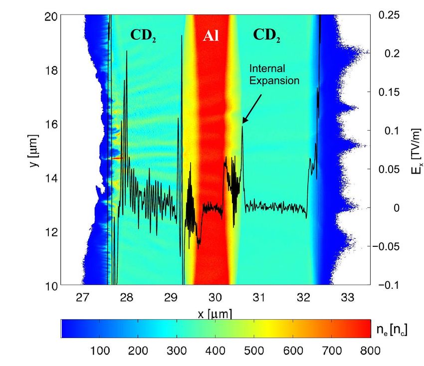
Targets for high repetition rate laser facilities                                                                                                            3

             2.1. Targets for dynamic compression physics                                            matter. On laser only facilities, laser–plasma backlighters
                                                                                                     can be used to measure X-ray diffraction (XRD), wide angle
             Dynamic compression physics is one of the largest science                               X-ray scattering (WAXS) and small angle X-ray scattering
             fields studied at high-energy laser facilities[1] . In such                             (SAXS) patterns, as well as absorption spectra in X-ray
             experiments, laser pulses with several J up to kJ of energy                             absorption near edge structure (XANES) and extended X-
             and durations between 100 ps and tens of ns compress solid                              ray absorption fine structure (EXAFS), or direct imaging
             density matter samples to extreme pressure (hundreds of                                 by X-rays. With the development of X-ray-free electron
             GPa) and temperature (several 1000 K up to 104 K and                                    lasers (XFELs), energy-resolved scattering has become more
             more) conditions. These conditions can be achieved with the                             easily accessible, using inelastic X-ray scattering (IXS) and
             direct ablation technique: the laser impinging onto the target                          X-ray Thomson scattering (XRTS), while still being able
             surface produces a plasma which rapidly expands, driving                                to utilize optical diagnostics[17, 18] . Various geometries
             a corresponding shock wave into the target via the rocket                               can be used, with the X-rays and optical beam co-linear,
             effect, heating it and compressing it.                                                  transverse or at other angles and multiple optical beams
                Prototypical experiments for investigating the properties                            can drive counter-propagating shocks. Figure 1 shows an
             of matter at such extreme pressure and temperature states                               example of experimental setup combining VISAR and XRD
             include equation of state (EOS) measurements, study                                     diagnostics to study shock compression of graphite samples
             of high-pressure/high-temperature phase diagrams and                                    at the Matter at Extreme Conditions (MEC) endstation of the
             new superdense phases[2] , phase transition processes and                               Linac Coherent Light Source (LCLS). In each case, target
             kinetics (for instance: grain nucleation and growth in                                  design must be able to accommodate multiple diagnostics,
             extreme conditions)[3] , mechanisms of solid deformation                                taking into account the shock geometry and laser parameters.
             at high strain rate[4] , transitions between solids and warm                               The repetition rate of current shock-compression experi-
             dense liquids[5] , and the structure of those liquids[6] .                              ments at combined laser–X-ray facilities is of the order of
             Besides the intrinsic interest for material science, these                              about 1 shot/10 min to 1 shot/min and the typical number
             studies find application in planetary physics, astrophysics,                            of shots of an experimental campaign is of the order of
             inertial confinement fusion (ICF) and laser-based industrial                            100–500. At laser only facilities, the repetition rate can
             processes[7] . For example, a sophisticated knowledge                                   be lower (shot/h or even shot/day), therefore the number of
             of matter properties at pressures around 10 Mbar is                                     samples needed for an experiment can be considerably lower.
             required in order to reliably model the cores of giant                                  The possibility of reaching higher repetition rates (0.1 Hz
             gaseous planets such as Jupiter and Saturn, and large rocky                             or better) and collecting data on a larger number of shots
             exoplanets[8] . In particular, the chemistry of low- and                                would offer new perspectives in this field, for example in
             mid-Z material mixtures at high-pressure/high-temperature                               the investigation of materials with poor scattering properties
             conditions strongly influences the formation and evolution                              (i.e., low-Z materials, liquids), in the study of compression
             of planets in extrasolar systems[9] . On shorter timescales,                            pathways and phase kinetics, and in the collection of data
             similar conditions are also present in meteor impacts[10]                               points along the Hugoniot and ramp compression curves. In
             or collisions of planetoids[11] . Other fundamental physical
             phenomena under investigation include dynamic properties
             of warm dense matter (WDM) in general, anisotropy of
             shock propagation, solid and liquid phase transitions. In
             addition to the prototypical Hugoniot shock compression[12] ,
             a wide variety of compression schemes exist such as quasi-
             isentropic (ramp) compression[13] , multiple-shock[14] , de-
             caying shocks[5] , reverberating[15] and colliding[16] shocks.
             These schemes are usually based on specific geometries,
             laser temporal profiles and target designs.
                When investigating matter in extreme states, well-
             understood optical diagnostics are generally used to de-
             termine the conditions that the sample has been driven
             to. These are primarily Velocity Interferometer System
             for Any Reflector (VISAR) to measure the shock velocity
                                                                                                     Figure 1. Schematic view of the experimental setup used at the MEC
             and transit times and extract the density and pressure from
                                                                                                     endstation of the LCLS to study dynamic compression of graphite samples
             known EOS relations, and Streaked Optical Pyrometery                                    to pressures between 20 and 230 GPa. The VISAR system recorded
             (SOP) for the temperature. More recently, X-ray diagnostics                             the shock transit time providing information on the shock velocity. The
             brought new capabilities to further understand the atomic                               microscopic state was probed by XRD. Image reproduced from Ref. [10],
             and microscopic structures of the bulk of the compressed                                licensed under CC-BY 4.0[19] .

Downloaded from https://www.cambridge.org/core. 29 Jul 2021 at 20:21:50, subject to the Cambridge Core terms of use.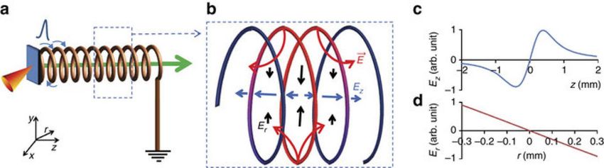
4                                                                                                                                            I. Prencipe et al.

       addition, higher repetition rates would allow for accumu-
       lating better statistics for synchrotron radiation and XFEL
       diagnostics and better spatial as well as spectral resolution
       for IXS and XRTS, or scanning X-ray parameters such as
       the X-ray energy for EXAFS.
          Target design and optimization are in general carried out
       by the user group or collaboration. A specific design has to
       be made to achieve the desired thermodynamic states while
       taking into account the laser parameters and diagnostics
       requirements (geometry, atomic and microscopic structures
       for X-rays, optical windows and properties for VISAR and
       SOP). Target needs appear quite homogeneous across the
       community and similar target structures are used by different
       groups working at both XFEL and synchrotron radiation
       facilities. Typical targets used for laser compression ex-
       periments are either single component foils (whether poly-
       crystalline or single crystal) up to 200 µm thick, sometimes
       with thin coating, or multilayer samples. In the latter
       configuration, the sample is enclosed in a sandwich structure
       (see Figure 2) including: an ablator, a shield (if needed), the
       sample itself and a window.
          The advantage of using an ablator, instead of directly
       ablating the sample, is to confine the laser-produced coronal
       plasma to the front layer and therefore to reduce gradients
       in the sample under investigation. Also, a proper choice
       of the ablation material helps in reaching extreme high
       pressure as a result of impedance mismatching. Finally it
       mitigates pre-heating in the sample and helps smoothing
       of small-scale spatial variations of the laser beam. Typical
       ablators are plastics, such as Parylene N, polyethylene and
                                                                                                Figure 2. Examples of typical multilayer targets used for dynamic
       polypropylene, or aluminium[20] .                                                        compression physics experiments: (a) in the simplest configuration the
          The sample thickness should be optimized for the X-                                   sample is coated with a low-Z layer (ablator), and occasionally with a
       ray diagnostics and laser properties as well as for the time                             preheat layer; (b) placing the sample layer between solid plates prevents
                                                                                                expansion and maintains high-pressure conditions longer; (c) complex
       scale of the phenomena under investigation. For example,                                 sample allows measurement of shock pressure by VISAR reflection from
       the attenuation length of X-rays in the target material must                             pressure standard (quartz) while also containing the sample.
       be taken into account to avoid loss of signal due to X-ray
       absorption in the sample. Another important aspect is that
       the ablator and back window must adhere perfectly to the                                    A high-Z shield layer might be necessary to prevent pre-
       sample to avoid surface roughness, cracks and porosity and                               heating from hard X-rays emitted by the laser-produced
       therefore prevent distorted shock front and thermodynamic                                coronal plasma.
       inhomogeneities. A good adherence is generally obtained                                     The thickness of the different layers has to be optimized
       with coating techniques or using a thin glue layer. The latter                           to ensure that homogeneous thermodynamic conditions are
       should be avoided at the sample–window interface which is                                maintained for longer than the time scale of the process
       important for VISAR measurements.                                                        to be observed or of the X-ray probe duration (typically
          Windows are used to act as a tamper and to maintain                                   several hundreds of ps for synchrotrons and several hundreds
       the thermodynamic conditions avoiding strong release in                                  of fs for XFELs). In addition, if a sample is too thick,
       vacuum. The window should be transparent both to X-                                      release waves from the ablating material may dramatically
       rays and visible light for the diagnostics not only at ambient                           reduce the pressure in a portion of the sample. A sandwich
       conditions but also under compression (i.e., diamond, which                              target can also be designed to reach off-Hugoniot states or
       is optimal for X-ray transmission, becomes opaque around                                 to sustain the peak pressure for longer time (few ns)[21] .
       100 GPa). Typical window materials are quartz, lithium                                   In this case, the sample can be embedded between two
       fluoride, sapphire and diamond. The window rear face                                     layers of a material with impedance similar to the studied
       should have an antireflection (AR) coating for the VISAR                                 sample. However, the total target thickness should not be too
       probe laser.                                                                             large with respect to the laser spot size to avoid shock front

Downloaded from https://www.cambridge.org/core. 29 Jul 2021 at 20:21:50, subject to the Cambridge Core terms of use.
Targets for high repetition rate laser facilities                                                                                                              5

             erosion from the borders[20] . Also, as already mentioned,
             the thickness of the multilayers has to be adapted for X-ray
             diagnostics.
                Hydrodynamic codes are currently used to model the
             wave interactions within the target, such as for example
             Multi[22] , Esther[23] and Hyades[24] . These codes simulate
             the laser–matter interaction by calculating energy deposition,
             hydrodynamics and mechanics, thermal conductivity, and
             radiation transfer, using available data of EOS, materials                              Figure 3. Scheme of iron–nickel alloy samples produced for ESRF
             opacity, optical index and emissivity. At the moment, few                               experiments using an integrated process including four steps performed by
                                                                                                     different companies.
             hydrodynamic codes are freely available for the community,
             although other codes can be requested directly from the au-
             thors or purchased with licence. 2D codes also exist and can                            with thin glue layers. However, the quality, reproducibility
             be used to check the planarity of the shock wave propagating                            and thickness uniformity of the additional adhesive layers are
             in the sample[25, 26] . By expanding the capabilities to a                              critical for the interpretation of experimental results, as they
             wider range of academic users, the hydrocodes could benefit                             can lead to nonhomogeneous shock front and to different
             from being made more accessible, user-friendly and with                                 break-out times (i.e., time that the shock takes to reach the
             improved documentation. In addition, effects of phase tran-                             rear target surface). Gluing techniques can also prevent
             sitions, grain size, pores, speckles in the laser, are generally                        mass production of targets. In general, reproducibility within
             not included in these codes and models would require more                               a few percents is desired for layer properties (especially
             detailed input (i.e., EOS, phase transitions).                                          thickness and density) and the initial thickness, density,
                Target fabrication and characterization techniques (and the                          crystalline phase, orientation, texture, grain size, reflectivity
             resulting quality, reproducibility and cost of the samples)                             and composition of layers must be characterized in advance.
             need to be taken into account in the target design phase. As a                          As mentioned before, another important factor is the quality
             consequence, iterations between users and target fabrication                            of the interface between sample and transparent windows,
             groups or companies are needed to develop a final target                                calling for specific surface treatments when possible since
             design. In the optimal case, target production can be com-                              polished surfaces enhance the shock uniformity. Separation
             pleted using coating techniques, as for example: physical                               of targets produced in large sheets is usually performed by
             vapour deposition (PVD) for metallic films, chemical vapour                             laser cutting or a focused ion beam (FIB). Other techniques
             deposition (CVD) for compounds (including electron beam                                 used by specialized target fabrication groups and companies
             CVD for oxides and salt structures deposition) and Parylene                             include laser cutting, surface polishing (including ion polish-
             deposition. However, coating processes only grow layers                                 ing), thermal fusing, lithography, etching, laser drilling and
             with thickness up to approximately 30 µm (depending on                                  micromachining.
             the coating composition and on the substrate) and growing
             single crystals can be complicated and expensive. Therefore,
             targets are often assembled by gluing the above-mentioned                               2.2. Targets for electron transport and isochoric heating
             layers with ordinary glue, formvar-based glue or UV-cured
             adhesives. In most cases, different laboratories and com-                               Investigation of the processes by which energy can be
             panies are involved in the production of a single batch of                              transferred into a dense plasma is, because of the plasma’s
             targets. For example, the production of iron–nickel alloy                               opacity, as big a field as the study of the properties of the
             samples with a double diamond window, an AR coating and                                 heated plasma. In this area, energy requirements and time
             an ablator (illustrated in Figure 3) for experiments performed                          constraints require laser pulses with energy 1–1000 J, pulse
             at ESRF was split into four processing phases performed by                              length below 1 ps and intensity above 1018 W/cm2 . Such
             four different companies: (i) diamond windows production                                pulses ionize the target (stopping the light at the surface)
             (Applied Diamonds, 6 weeks), (ii) AR deposit (Fichou, 3                                 converting a fraction of the laser energy into relativistic
             weeks), (iii) deposit of the iron–nickel alloy (DEPHIS, 9                               electrons with temperatures up to few MeV, which transfer
             weeks) and (iv) polymer coating for ablator (Scitech, 3                                 energy deeper into the target[27] . For high contrast pulses
             weeks). This approach resulted in a long preparation time                               with tens of fs duration the main pulse interacts with an
             (5 months only for processing) and in an increase of the                                intact target surface (hundreds of nm preplasma). The target
             sample cost (more than 300 Euro/target). In general, a                                  is static during the pulse; no electron recirculation, bulk
             rough estimate of the cost of targets for shock-compression                             heating or ion expansion occurs for that time. For longer
             experiments ranges between 104 and 105 Euro/campaign,                                   pulses (ps) the target surface starts expanding before the
             mainly in labour costs. In some cases, home-made targets are                            interaction is over, thus relativistic oscillations of the critical
             used: as-purchased rolled foils are glued to plastic ablators                           density surface, electron recirculation and bulk heating take

Downloaded from https://www.cambridge.org/core. 29 Jul 2021 at 20:21:50, subject to the Cambridge Core terms of use.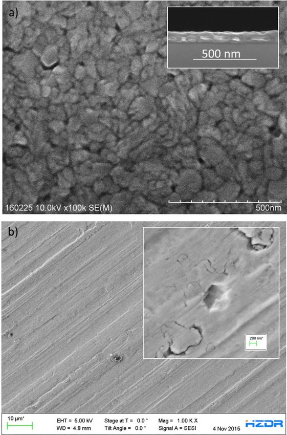
6                                                                                                                                               I. Prencipe et al.

       place during the interaction[28] . In both cases, the hot laser-
       generated electrons propagate into the bulk of the material
       in timescales much shorter than the plasma hydrodynamic
       expansion, and gives rise to intense electromagnetic fields
       and charge separation effects. As a consequence, a return
       current of low temperature bulk electrons (up to MA) is
       generated, which is responsible for Ohmic heating of the
       target bulk[29–31] . Therefore, extreme matter states with
       near solid density and extremely high temperatures are
       generated before the target expands significantly. These
       states are known as WDM (temperatures up to a few keV,
       see also Section 2.1), or HED states (energy density above
       100 kJ/cm3 ).
          WDM and HED experiments look at the structure and
       energy flow between the various components of the plasma.
       Specific HED science questions include understanding the
       type and growth of instabilities at the plasma surface and
       energetic particle transport within it, energy interchange                               Figure 4. Schematic layout of the experimental configuration used to
                                                                                                investigate proton-driven isochoric heating of polycrystalline graphite rods
       between highly energetic particles, ambient electrons, nuclei                            (125 µm × 300 µm × 3 mm). Reprinted figure with permission from
       and photons. These kinds of experiments find application                                 Ref. [32]. Copyright 2010 by the American Physical Society.
       in laboratory astrophysics, study of relativistic plasmas (in-
       stabilities), inertial fusion studies, and investigation of the
       fundamental physics of laser-driven particle and radiation                               generated by concerted particle motion, but also to modify
       sources (see Section 2.3).                                                               the target surface density and atomic number profiles. The
          The number of shots required for electron transport and                               use of secondary radiation sources to probe WDM and HED
       isochoric heating experiments depends on the specific exper-                             states (pump–probe experiments) requires secondary targets
       iment. In general, tens of shots are needed for tracing the                              (backlighters) for tailoring or converting the primary (pho-
       thermal and structural evolution of the system in time. This                             ton) beam to more appropriate excitations (narrow band fluo-
       number can grow if the effect being investigated is small                                rescence, protons, X-rays). As a result, the completed target
       compared to shot-to-shot or sample-to-sample variations,                                 assemblies often require addition of a 3D superstructure in
       or if the added variance (due to instabilities or chaotic                                the mm scale (multi-target assembly). Target superstructure
       process) is the parameter being studied. Parameter scans are                             can also be used for shielding the detector while giving
       normally performed to determine the dependence of system                                 access to the target region under investigation. Figure 4
       evolution on initial target properties and laser parameters.                             shows an example of multi-target configuration used to
       For these cases, the total number of shots per campaign                                  investigate proton-driven isochoric heating of polycrystalline
       might encompass thousands of individual shots. The shot                                  graphite rods (125 µm × 300 µm × 3 mm). Protons were
       repetition rate in current facilities (typically much lower than                         produced by the interaction of a laser pulse with a thin Au
       1 min−1 ) is too low to allow such experiments.                                          foil, while the X-ray probe was generated by the interaction
          HED and WDM experiments involve targets that are                                      of a laser pulse with a Ti foil. An Au shield was required
       sufficiently large and/or dense for reasonable opacity and                               to block secondary radiation produced in the laser–matter
       that endure for sufficiently long to approach equilibrium. A                             interaction[32] .
       variety of approaches (singly or in combination) are used for                               Hereinafter, we report a few examples of possible targets
       coupling energy in through the surface; for example, cones                               exploiting specific geometries or layer sequences for the
       to concentrate the light and resulting electrons; modulated                              investigation of isochoric heating and electron transport
       surface topology, density and/or atomic number to focus EM                               mechanisms.
       fields (such modulations can also be produced by fielding                                   Hollow cone structures can be used to guide light and
       with prepulses with known properties). In some cases                                     photo-generated electrons into a target at its tip. MeV
       structures can be built into the target to enable detection                              electrons in the cone are generated via a direct light pres-
       of, for example, hot-electron–stimulated fluorescence or a                               sure acceleration mechanism, that increases the number and
       buried layer expansion. X-ray radiation from XFEL or                                     energy of electrons reaching the cone tip and heating it.
       laser-driven (secondary) sources can be used for diagnostics                             For p-polarized radiation (i.e., electric field perpendicular
       since X-ray scattering techniques are sensitive to nuclear                               to the cone wall), bunches of electrons are pulled from the
       positions and density fluctuations, either thermal or caused                             cone surface towards the centre of the cone where they are
       by concerted particle motions. Laser-driven proton sources                               accelerated by the Lorentz force[33] . Depending on the shape
       can be used not only to measure electromagnetic fields                                   of the target at the cone tip, different effects can be studied.

Downloaded from https://www.cambridge.org/core. 29 Jul 2021 at 20:21:50, subject to the Cambridge Core terms of use.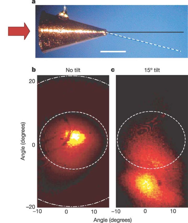
Targets for high repetition rate laser facilities 7
Figure 5. Qualitative spatial distributions of electric field (left) and electron
energy density (right) produced by the interaction of an ultra-intense laser
pulse with a flat-top cone target. From T. Kluge.
For example, a reduced mass target at the cone tip enhances
proton acceleration performances[34] . In this configuration,
the Target Normal Sheath Acceleration (TNSA) field (see
Section 2.3) is due to two electron populations, produced in
the cone and at the reduced mass target surface. Figure 5
shows qualitatively the spatial distribution of electric field
and electron energy density for flat-top cone targets. Another
possibility is to use a thin wire positioned at the tip of a
hollow cone and aligned along the cone axis or at some Figure 6. (a) Hollow cone target with thin wire at the tip (diameter 5 µm,
angle, as shown in Figure 6. In this geometry, the cone length 1 mm): the black line shows a wire aligned along the cone axis, the
dashed line represents a wire tilted by 15◦ from the cone axis (size bar is
guides the laser light and laser-generated hot electrons into
300 µm). Spatial distribution of electrons with energy above 3.5 MeV for a
the wire, increasing their energy density by more than one wire positioned along (b) the cone axis and (c) tilted by 15◦ . Reprinted with
order of magnitude[35] . permission from Macmillian Publishers Ltd: Nature[35] , copyright 2004.
WDM states have also been recently studied by irradiating
the upper base of cylindrical Ti targets (50 µm diameter and
120 µm length)[36] . This configuration separates regions
heated by plasma absorption mechanisms from those heated
by hot-electron propagation only (up to 1 mm from the
laser–target interaction region, reaching temperatures up to
50 eV). In addition, the temperature gradients along the
wire permit simultaneous investigation of regions in different
temperature regimes, provided the availability of spatially
resolved diagnostics.
Multilayer targets allow not only to study the dependence
of electron transport on the material properties, but also to in-
vestigate phenomena occurring at the interface between two
layers. Electron resistive collimation was investigated using
Al targets (transverse size about 1 mm × 1 mm) embedded
with a layer of gold or molybdenum about 10 µm thick, a
layer of copper (22 µm) to trace the electron beam profile
110 µm behind the Au or Mo layer and a conductive carbon
layer (1 mm thick, transverse size about 5 mm × 3 mm)
Figure 7. 2D spatial distribution of free electron density and longitudinal
to avoid electron reflux[37] . The high-Z layer in this target electrostatic field at 43 fs prior to the peak laser intensity on the target. The
collimated the energy flow, their thickness was selected to density distribution shows that internal expansions compress the CD2 layer
have similar shock transit times; the other layers were used to a higher density with a factor of about 1.5. The compression is also
associated with enhanced ion heating in the compression layers. Strong
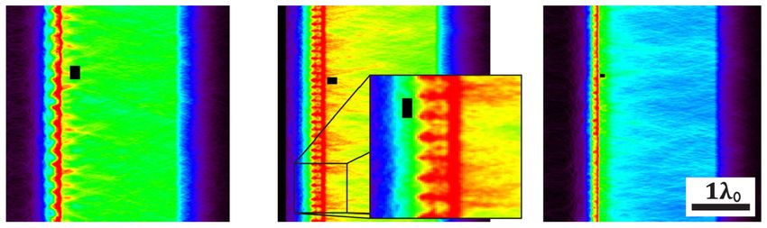
for depth-specific imaging of deposited energy. Three-layer ripples and filaments are clearly seen in the front surface and bulk of the
targets (CD2 –Al–CD2 ) were considered for the investigation buried layer target. The detailed simulation parameters and physics can be
of buried layer heating by internal expansion[38] . The found in Huang et al.[38] . From L. G. Huang.
electron density gradient at the interface between Al and
Downloaded from https://www.cambridge.org/core. 29 Jul 2021 at 20:21:50, subject to the Cambridge Core terms of use.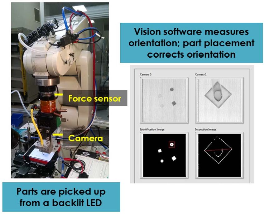
8                                                                                                                                          I. Prencipe et al.

       Figure 8. Simulated energy density distribution showing the growth of seeded Rayleigh–Taylor instabilities in samples with an initial surface roughness
       containing several spatial frequencies. For each image, the black bar illustrates the maximum spatial frequency of the initial roughness, the minimum spatial
       frequency is twice this size. Reproduced from Ref. [40], with the permission of AIP publishing.

       CD2 generates a pressure gradient resulting in the expansion
       of the Al layer. The Al layer acts as a piston compressing the
       CD2 layer. This directed collective ion motion is converted
       into thermal motion in the CD2 layer. Figure 7 shows the
       electron density distribution and the electric field driving the
       Al layer expansion.
          Engineered targets can also be used to characterize and
       understand structural instability growth at a dense plasma
       surface, that leads to electron filamentation in the bulk of
       the target (see Figure 8) and, in some cases, to a pattern
       in the spatial profile of ions accelerated by TNSA (see Sec-
       tion 2.3)[39] . Particle in cell (PIC) simulations demonstrated
       that the spatial frequency of roughness on the target surface
       influences the formation of instabilities and electron filamen-
       tation and that the instability can be seeded by selecting an
       appropriate mixture of spatial frequencies[40] . Therefore,
       targets with patterned front surface can be used to seed insta-
       bilities with a specific spatial frequency. Such samples could                           Figure 9. Scanning electron microscopy (SEM) micrograph of a grating
                                                                                                with period around 1 µm. Courtesy of T. Schoenherr, Y. Georgiev and A.
       be produced, for example, using lithography to scribe the                                Erbe, Institute of Ion Beam Physics and Materials Research, HZDR.
       target surface with grooves of various depths and spacing;
       this ensures that a single, 1D spatial frequency will dominate
       the instability with the instability sheets oriented along the
                                                                                                addition, the energy associated with many HED or WDM
       probe beam for best detection. Figure 9 shows an example
                                                                                                experiments requires the targets to be isolated from one
       of such a structure.
          Construction of the core of these targets, even micro-                                another to provide access for detectors and to avoid damage
       cones and complex backlighter targets, is generally compat-                              to upcoming targets (sheets of targets can only be used for
       ible with the standard complement of coating and masking                                 pulse energies up to about 1 J). It is not feasible to manually
       techniques used on Si and semiconductors (even though                                    create large numbers of such target assemblies – automation
       low density foam is sometimes called for and is combined                                 will be required. General Atomics has developed automated
       with others only with difficulty). Such an approach has the                              target assemblers (see Section 3); they have to be trained for
       capability to make many thousands of targets on a single                                 each new target type, but experience shows this approach
       wafer with reasonable cost and increased accuracy[41, 42] .                              is cost-effective for runs with more than 50–100 targets.
       In addition, batch production techniques have been devel-
                                                                                                The substantial (few to ∼10 mm depending on pulse length
       oped by the Central Laser Facility (CLF) Target Fabrication
       Group to manufacture up to 50 cone targets per day to high                               and energy, and target design) separation required to prevent
       precision and low internal wall roughness (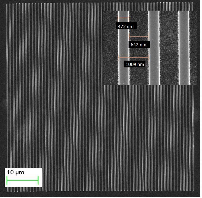
Targets for high repetition rate laser facilities                                                                                                            9

             2.3. Targets for laser-driven particle and radiation sources

             The production of laser-driven secondary radiation sources
             is a very active research area in both long (ns) and short
             (sub-ps) pulse facilities. A wide range of sources have been
             investigated in the past decades such as electrons, ions, X-
             rays (coherent and incoherent), gamma rays and neutrons.
             A remarkable variety of target types can be used for the
             generation of secondary radiation, depending on the source
             type and desired properties, and different challenges must
             be addressed for the production and characterization of each
             type of target.                                                                         Figure 10. Schematic illustration of the production of X-rays in the
                In general, research activities in this field can be classified                      interaction between a laser pulse and a gas target. The betatron motion
                                                                                                     of electrons propagating in the pulse wake results in the emission of
             into two categories. The first (and up to now dominat-
                                                                                                     synchrotron radiation.
             ing) category includes exploratory investigation aimed at
             understanding the basic physics and at improving the source
             properties, or at generating new types of sources. A large                              away from regions with high electromagnetic field gradient
             number of experiments in this field are aimed at developing                             driving longitudinal electron density waves (laser wakefield)
             new types of targets to improve the properties or the control                           and electrons are accelerated due to the charge separation
             of laser-generated radiation and particles. This kind of                                generated in the plasma[47] . Short (fs) pulses of synchrotron
             investigation would benefit from the implementation of high                             radiation are produced due to betatron oscillations occurring
             repetition rate laser systems since shot-to-shot variations
                                                                                                     during the electron propagation in the wake of the laser
             can be very pronounced. The number of targets required
                                                                                                     pulse (Figure 10)[48] . Targets for electron acceleration are
             for exploratory studies is a few hundreds (up to 1000)
                                                                                                     normally gas jets, gas cells and discharge capillaries.
             per run. Fast prototyping is essential for this kind of
             experiment that does not require a huge number of targets                                  Supersonic gas jets (with Mach number up to 10) are
             of the same type, but rather parametric scans. A second                                 the most common type of target for laser-driven electron
             category of experiments is aimed at generating sources with                             acceleration experiments. Gas jets have normally high
             high reproducibility, exploiting the best sources that have                             electron density, between 1018 and 1019 cm−3 and provide a
             been developed in explorative campaigns. The goal of such                               controllable and laminar flux. One of the main issues related
             experiments is to offer particle and radiation sources to                               to this kind of target is that nozzles can be damaged due to
             users who are not specialists in laser–plasma interactions for                          the plasma plume produced in the laser–gas interaction. For
             applications, for example, in material science, radiobiology                            example, stainless steel nozzles can be used for less than 104
             and medical science. The generation of secondary particle                               shots before the gas flux starts showing turbulence due to
             and radiation sources for applications is one of the goals of                           nozzle damage. Also, it would be important to ensure the
             some upcoming large-scale facilities such as Apollon, ELI-                              durability of magnetic valves when used at 1 kHz. Other
             Beamlines and the LIGHT beamline (Laser Ion Generation,                                 challenges include 3D shaping and the formation of sharp
             Handling and Transport) at GSI Darmstadt[44] . This applica-                            gradients in the flow from the nozzle for low density gas jets
             tion requires operation at high repetition rates (1–10 Hz) and                          (1013 cm−3 ). The relatively high density values typical of
             methods for mass production of targets (tens or hundreds of                             gas jets allow the production of intense electric fields (hun-
             thousands) at reduced cost.                                                             dreds of GeV/m), since the maximum magnitude of electric
                Hereinafter, we discuss examples of targets used for the                             field in a plasma wave (so-called cold wavebreaking limit
             generation of secondary sources and the main challenges                                                              1/2
                                                                                                     E wb ) is proportional to n e . However, the distance over
             for each target type. Established target technologies exist                             which electrons can be accelerated is limited by three factors:
             for some types of targets, while improvement (e.g., better                              (i) defocusing of the pump laser beam, (ii) depletion of the
             modelling, mass production, cost reduction, shaping) or                                 driving laser energy and (iii) dephasing length (L D ), beyond
             major additional development is required for other target                               which electrons start being decelerated by the wakefield.
             concepts.                                                                                                                             −3/2
                                                                                                     The dephasing length is proportional to n e . Thus, the
             2.3.1. Gas targets                                                                      maximum energy reachable by accelerated particles (∼E wb ·
             Gas targets are mainly used for laser-driven electron ac-                               L D ∼ n −1
                                                                                                              e ) decreases for increasing density. Therefore, gas
             celeration and X-ray production[45] . The electron density                              cells with electron density between 1016 and 1018 cm−3 are
             in a gas (n e ∼ 1016 –1019 cm−3 ) is well below the plasma                              often used for laser-driven electron acceleration. The high
             critical density (i.e., underdense plasma, allowing for laser                           threshold for self-guiding in gas cells, however, makes it
             propagation)[46] . As the laser pulse propagates in an un-                              difficult to keep the pulse focused over the whole gas cell
             derdense plasma, the ponderomotive force pushes electrons                               length and limits their use to PW class laser systems[49] .

Downloaded from https://www.cambridge.org/core. 29 Jul 2021 at 20:21:50, subject to the Cambridge Core terms of use.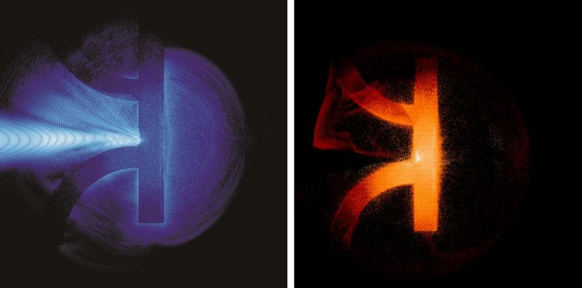
10                                                                                                                                              I. Prencipe et al.

       Figure 11. Adjustable length gas cell developed by SourceLAB. Courtesy
       of F. Sylla.

                                                                                                Figure 12. Cross-section and assembly of fast electro-valve and nozzle
       Figure 11 shows an adjustable length gas cell developed by                               for sub-millimetre He gas jets with peak density above 1022 atoms cm−3 .
       SourceLAB. On the contrary, a good focal spot quality is                                 The nozzle throat diameter is smaller than 400 µm and He pressure ranges
       in general maintained over the whole acceleration length                                 between 300 and 400 bar. Reprinted from Ref. [55], with the permission of
                                                                                                AIP Publishing.
       in discharge capillaries made, for example, of alumina or
       sapphire and with a diameter of hundreds of µm[50, 51] .
       In this configuration, a capillary is filled with gas through
       holes drilled at each end. The gas is ionized by pulsing
       a discharge through the capillary and the heat dissipation
       by the capillary walls allows control of plasma density,
       which is minimum along the capillary axis. This effect
       contributes to maintaining a good focal spot quality along the
       whole capillary length. Gas density for discharge capillaries
       is about 1017 –1018 cm−3 ; below 1017 cm−3 the electron
       density is too low for discharge propagation. Capillaries
       are fabricated via well-established techniques, such as laser
       machining, selective etching or milling of two plates that are
       subsequently joined together. The capillary inner surface
       should have optical quality for preventing scattering, thus
       its roughness should be controllable. These techniques are
       currently available, but expensive. Therefore, solutions to                              Figure 13. Schematic illustration of TNSA – relativistic electrons produced
                                                                                                in laser–matter interaction propagate through the target and form an electron
       avoid capillary damage and ensure survival at high repetition                            sheath at the target rear surface producing a charge separation and intense
       rates (1 kHz and beyond for collider applications) should be                             electric fields.
       developed[52] . A general issue which is common for gas
       jets, cells and capillaries is the need for better modelling and
       computational tools.
          Gas jet targets have also been used to investigate laser-                             electron bunches in the interaction of relativistic laser pulses
       driven ion acceleration occurring in the target volume. Ener-                            with solid surfaces has been recently observed and attributed
       gies of ions produced with low density gas jets are normally                             to vacuum acceleration of electrons emitted by a plasma
       in the sub MeV range and show in some cases narrow                                       mirror[58] and to the excitation of high field plasmons from a
       energy spread[53, 54] . Gas jets with density higher than                                modulated surface[59] .
       1021 cm−3 have been developed in the last few years[55, 56]                                 The most common scheme for laser-driven ion accelera-
       and are now commercially available (e.g., from SourceLAB,                                tion is known as TNSA and was first observed in 2000 with
       see Figure 12). Over-critical gas jets offer the perspective                             1–125 µm thick Al, Au and polymer foils[60, 61] . TNSA is
       of producing higher ion energies by acceleration mecha-
                                                                                                based on the generation of relativistic electrons by the laser
       nisms based on a propagating shock generated by the laser
                                                                                                pulse at the target surface. These electrons recirculate in the
       pulse[53, 57] .                                                                          target and form a sheath beyond the nonilluminated surface
       2.3.2. Solid targets                                                                     of the target. The electron sheath generates a charge sepa-
       Solid targets are mainly used for laser-driven ion acceler-                              ration and intense electric fields (MV µm−1 ) that accelerate
       ation and neutron production, even though generation of                                  light ions absorbed on the rear target surface and ions from

Downloaded from https://www.cambridge.org/core. 29 Jul 2021 at 20:21:50, subject to the Cambridge Core terms of use.
Targets for high repetition rate laser facilities 11
the target bulk (see Figure 13). Accelerated ion bunches
have exponential energy spectrum, cut-off energies of several
tens of MeV/nucleon, are collimated along the target normal
direction and contain about 1011 ions/bunch[62, 63] .
Targets for laser-driven ion acceleration range from simple
foils (any composition, thickness from tens of nm to tens
of µm), to multilayer targets (sometimes with structured
surfaces), to 3D assemblies.
Thin foils have been largely used to investigate TNSA.
Parametric scans were performed to investigate the effect
of thickness on the acceleration mechanism with different
laser contrast ratios[64, 65] , observing an enhancement of
maximum ion energy for decreasing target thickness. Para-
metric scans in foil thickness are particularly interesting as
they allow investigation of the transition between regions Figure 14. Schematic illustration of laser-driven ion acceleration from a
dominated by different acceleration mechanisms. TNSA was metallic foil with a hydrogen-rich micro-dot on the back side. Reprinted
found to be dominant for µm and sub-µm thick targets, with permission from Macmillan Publishers Ltd: Nature[77] , copyright
2006.
while for thinner targets (10–100 nm) other acceleration
schemes were observed, as for example radiation pressure
acceleration (RPA)[66–68] . The RPA regime allows pro-
duction of ion bunches with narrow energy distribution
and is dominant for circularly polarized laser radiation and
normal incidence, as the generation of relativistic electrons
is efficiently suppressed in these conditions. In addition,
RPA requires high laser contrast (>1010 ), as prepulses or
pulse pedestal could destroy the target before the interaction Figure 15. SEM microscope images of a single layer of polystyrene spheres
(a) with diameter 0.9 µm and regularly arranged (hexagonal pattern); (b)
with the main pulse. Commercially available foils with with diameter 0.26 µm (irregular pattern due to substrate cutting process).
thickness 61 µm are normally produced by CVD or PVD, (c) Atomic force microscopy (AFM) characterization of a commercially
available foil (Al 2 µm, Goodfellow). Image reproduced from Ref. [79],
while foils with thickness of several µm are normally rolled
licensed under CC-BY-NC-SA 3.0[80] .
from thicker foils. Ultrathin targets can be produced, for
example by spin coating thin polymer films onto a thick
support (an Si wafer), then floating them in water and
transferring them to a target holder[69] . Another option is to of maximum energy, number of accelerated particles and
use lithographic techniques to produce arrays of membranes
energy spectrum. Double-layer targets with a low atomic
on wafer. However, ultrathin membranes are fragile and
number coating on the nonilluminated side were studied to
can be damaged in transport from target laboratory to laser
obtain higher number of protons and proton energy[74] and to
facility or due to irradiation of neighbouring targets. The
use of liquid crystal films suspended in a metal frame has study the dependence of proton beam transverse modulations
been recently proposed as an alternative solution[70] (see on the roughness of the target rear surface[39] . Metallic
Paragraph 2.3.3). targets with hydrogen-rich micro-dots (with transverse size
Since the first observations of TNSA, engineered targets comparable with the laser focal spot area) allowed higher
have been used to investigate the acceleration mechanism
yields of ions with a narrow energy spectrum (see
and characterize the properties of accelerated ions: wedge Figure 14)[75–77] . Targets with nano and microstructured
targets permitted validation of the TNSA model[71] , targets
coatings were investigated, as well as patterned target sur-
with patterned rear surface allowed measurement of ion
faces: for example, nanosphere targets (see Figure 15)[78, 79] ,
emittance[72] and multi-target configurations allowed imag-
surface gratings[72, 81] and carbon foam coating[82, 83] (see
ing of the electron sheath[73] . Multilayer targets were inves-
tigated to achieve a better control of properties of accelerated Figure 16) have been tested to enhance the transfer of
ions and to enhance the acceleration performances in terms laser energy into the plasma; carbon nanotube films were
Downloaded from https://www.cambridge.org/core. 29 Jul 2021 at 20:21:50, subject to the Cambridge Core terms of use.12 I. Prencipe et al.
electrons into a reduced mass target (see Section 2.2)[33, 34] .
3D target geometries are generally more demanding as target
fabrication is concerned, since they are often produced by
assembling micromachined components.
Multiple target configurations are required for pump–
probe laser-driven ion acceleration experiments: laser-driven
proton and X-ray radiography were used to diagnose the
production of large-scale homogeneous plasmas[95] , the dy-
namics and structure of self-generated magnetic fields in
solid targets[96] , ultra-fast induced micro-lenses to focus
and energy-select laser-driven protons[97] , or, as already
mentioned, the evolution of the electron sheath at the rear
target surface[73] . Multiple target configurations are chal-
Figure 16. SEM micrographs of carbon foams produced by PLD with Ar as lenging since they require precision assembly (difficult to
buffer gas and different target to substrate distance, gas pressure, process scale to high numbers without automated processes) and for
duration: (a) 4.5 cm, 500 Pa, 3 min; (b) 8.5 cm, 100 Pa, 10 min. Image application in high repetition rate experiments, since two or
reproduced from Ref. [83], licensed under CC-BY 3.0[84] . more targets have to be fielded simultaneously.
The simplest target configuration for laser-driven neutron
generation consists in bulk deuterated polyethylene: DD
used for pulse focusing and temporal shaping[85] . While
fusion reactions occur due to collisions between deuterons
most of these targets were produced using standard coating accelerated at the front target surface with deuterium nuclei
techniques, others required extensive research and devel- in the target bulk (beam fusion, forward directed) or after
opment activities, as in the case of low density coatings: deuteron thermalization (thermal fusion, isotropic)[98–100] .
carbon foams produced by pulsed laser deposition (PLD) Multiple target configurations have been used to study laser-
and characterized by energy dispersive X-ray spectroscopy driven neutron generation in the so-called pitcher–catcher
(EDS)[86, 87] and carbon nanotube coatings deposited by geometry: protons or ions accelerated in a primary tar-
CVD[88] . Robust enhancement of proton energy was ob- get are then directed onto a secondary target acting as a
served with reduced mass targets (thin foils with limited converter[101, 102] . The converter can be a solid, but also a gas
transverse size) produced by lithographic techniques[89–91] . jet. For example, protons accelerated onto an LiF converter
Since TNSA ions are emitted along the rear target nor- produce neutrons via a 7 Li(p,n) reaction, another possibility
mal direction, bent targets have been tested as ion op- is to use beryllium or boron isotopes for (p,n) and (d,n)
tics: hemispherical, hemicylindrical and hemispherical tar- reactions. The latter geometry produced neutrons yields
get coupled with a conic structure[61, 92, 93] . Flat targets up to 1010 n.sr−1 . Of course, selecting a specific nuclear
grounded through bent wires or coils permitted charac- reaction (e.g., to produce neutrons in a specific energy range)
terization of return currents in the target and to simul- requires targets with well-defined elemental and isotopic
taneously perform ion energy selection, collimation and composition.
post-acceleration (see Figure 17)[94] . Ion energies up to 2.3.3. Other target types
67.5 MeV were obtained with flat-top cones exploiting a Other target types used for laser-driven radiation and particle
hollow cone structure to guide light and photo-generated sources include foams, cryogenic targets, liquid droplets and
Figure 17. (a) Schematic view of a flat target grounded through a coil. The return current flowing in the coil produces electric fields allowing for energy
selection, collimation and post-acceleration of laser-driven ions: (b) shows a scheme of the electric field configuration in the coil (snapshot), (c) and (d)
illustrate the electric field profiles inside the coil along the coil axis and in the transverse plane at the location of the peak of charge density along the coil.
Image reproduced from Ref. [94], licensed under CC-BY 4.0[19] .
Downloaded from https://www.cambridge.org/core. 29 Jul 2021 at 20:21:50, subject to the Cambridge Core terms of use.Targets for high repetition rate laser facilities 13
clusters.
Besides the aforementioned PLD and CVD methods for
low density coatings, a number of chemical techniques
are commonly used for the production of foam targets,
such as sol–gel polymerization, polymerization of the
continuous phase of high internal phase emulsions (poly-
HIPE) and freeze-dry technique with blowing agents
(carbon dioxide or aluminium nitrate). Aerogels and
organic acrylic macroporous and mesoporous foams are
usually produced by supercritical CO2 extraction process.
Mesoporous and macroporous acrylic foams are made from
polymerization of UV-initiated monomers dissolved in a
suitable solvent and deposited on a substrate or mould:
the wet gel is then transferred to a critical point dryer.
The production of 3D foam geometries can be obtained by
a combination of moulding[95] , also in combination with Figure 18. SEM micrographs of poly(4-methyl-1-pentene) foams prepared
from (a), (b) 1-hexanol, (c) 2-methyl-1-pentanol, (d) 2-ethyl-1-butanol.
photopolymerization[103] . Diamond machining is applicable Image reproduced from Ref. [109]. Copyright 2002 The Japan Society of
only for mechanically tough precursor gels[104] . For Applied Physics.
spherical targets, emulsion processes can be used[105, 106] :
viscosity is the crucial parameter to control the wall
thickness[107] . Interfacial polymerization allows production
of foams with a smooth membrane on the surface[108] . In
general, a fine control of the foam properties is achieved
by tuning the chemical composition of the precursor
reagents and the process parameters (see Figure 18). For
example, the foam nanostructure depends on the affinity
of polymer and solvent[109, 110] and gelation kinetics[111] .
Organic aerogels[112] are typically based on poly(4-methyl-
1-pentene)[109, 110, 113] . However, the size of oxygen
containing acrylic monomers is more controllable[103] and
resorcinol–formaldehyde resins have finer nanostructure
and higher affinity with metal cations[108] . Inorganic Figure 19. (a) LSTI: wiper and frame with a 4 mm aperture. (b) Liquid
aerogels can have a wide variety of compositions (i.e., SiO2 , crystal targets with four different thicknesses. Thickness is a function of
the blade sliding velocity. (c) Film production process: the blade slides
Ta2 O5 )[114] . Doping of foam with higher Z elements and across the aperture drawing the liquid. The film is formed within 2 µm of
fine control of the foam composition can be obtained by the same location each time due to the aperture 45◦ inner bevel. Reprinted
from Ref. [70], with the permission of AIP Publishing.
using monomers with controlled elemental composition[115]
or nanoparticle additives to the chemical synthesis solutions.
The main experimental issue is that low density targets development is still required to make this type of target
have necessarily some micro and nanostructure. These suitable for beamline applications. For example, the film
nonhomogeneities influence laser absorption and electron thickness depends strongly on the controlled delivery of very
transport. small volumes of fluid which can be difficult to implement.
Liquid crystal targets are produced directly in the in- The film thickness can also change in time due to fluid flow
teraction chamber by drawing a given volume of liquid after film formation. Thus the main challenges for this target
crystal (hundreds of nanolitres) with a sharp blade sliding concept are film thickness control and film stabilization.
across an aperture on a metal frame[70] . Figure 19 shows A possible drawback is the difficulty in incorporating high
the Linear Slide Target Inserted (LSTI) developed at the atomic number elements (as metals) in liquid crystal targets.
Ohio State University for the production of liquid crystal Cryogenic target devices were initially developed for in-
targets. Liquid crystal film thickness can be varied from ertial confinement fusion experiments. This class of targets
6 nm to several µm by changing the blade sliding velocity allows to study laser-driven ion acceleration with pure solid
and can be measured online by optical reflectometry (for low hydrogen or deuterium targets. Several laboratories have
repetition rates). In addition, a device for the production been developing systems for in situ formation of cryogenic
and positioning of films with repetition rate up to 3 Hz is targets by casting[116] , extrusion[117] and condensation[118] .
being developed at Ohio State University. However, some Casting is not suitable for production of targets with thick-
Downloaded from https://www.cambridge.org/core. 29 Jul 2021 at 20:21:50, subject to the Cambridge Core terms of use.You can also read