Team C5 - Fruit Ninja AR - Electrical and Computer Engineering
←
→
Page content transcription
If your browser does not render page correctly, please read the page content below
18-500 Design Report: 03/17/2021 1

 Team C5 - Fruit Ninja AR
 Author: Arthur Micha, Ishaan Jaffer, Logan Snow: Electrical and Computer Engineering, Carnegie
 Mellon University

 billion downloads, and requires a very quick swiping action [2].
 Abstract —The use of Virtual and Augmented Reality systems This swiping action works best without having to hold a bulky
has become exponentially popular in recent years. The human- controller, and any implementation that falls short of our design
environment interaction methods have become increasingly goals will lead to a rocky gameplay experience.
expensive and existing controllers are clunky objects that need to
be held. In this paper we propose a wearable glove system with
haptic feedback, which produces different vibrations. Our design
consists of Infrared LEDs, image processing, a RaspberryPi, an II. DESIGN REQUIREMENTS
Inertial Measurement Unit, a wearable Arduino, and two Infrared The main goal of the project is to create a smooth user
Cameras.
 experience that would be comparable to other products on the
 market. Breaking this down further, the glove needs to meet
 Index Terms — Haptic Feedback, Motion Tracking, Infrared
Tracking, Inertial Measurement Unit (IMU), Wearable the goals specified earlier in the introduction, in addition to
Technology, Game Controller, Bluetooth LE, Unity, Arduino, other qualitative specifications. The haptic feedback motor
Raspberry Pi on the glove must be calibrated to provide a vibration effect
 as strong as the rumble feature in typical game controllers.
 I. INTRODUCTION The quantitative metrics described earlier will be sufficient
 to design a game that runs smoothly, however, the game has
T HE first mainstream application of motion-tracking
 technology for video games was the Wii Remote,
developed by Nintendo for the Wii game console. Since then,
 to effectively take advantage of the positional data to offer a
 high quality experience. As such, there will be a calibration
motion tracking has also been explored in the Xbox Kinect and step at the beginning of the game where a user can mark each
most recently, various virtual reality (VR) controllers. The main of the four corners that they wish to use to bound the motion
drawback to the Wii Remote was its bulk, which made it non- area. All of these setup steps must be simple and quick so as
intuitive to use for some games that required abrupt motion. The to not cause unnecessary friction for the user before the game
Xbox Kinect solved this problem by removing the need for a can be played. Finally, to achieve our goal of providing a
controller altogether by using an array of sensors to detect lightweight and comfortable experience, the glove must not
motion from a single device sitting in front of the television. have a bulky microcontroller with loose wires exposed.
However, the Kinect was not without its own drawbacks. The
Kinect required a significant amount of space to function, and
lacked the ability to provide haptic feedback to the user, causing
a less immersive experience [1]. These drawbacks as well as the
expensive price of the Kinect led to its eventual discontinuation.
The market currently lacks a device that combines the strengths
of these two technologies. A motion-sensing glove can allow
for haptic feedback and high-quality motion detection while
removing the need to grip a bulky device and can work in a
small space.
 A successful implementation of this design should achieve
a number of quantitative goals that are intended to provide a
seamless user experience. The glove must output positional data
at a rate greater than or equal to 30Hz, which roughly equates
to the frame rate of most video games. The resolution must be
capable of detecting motion of as little as 1cm from a distance
of 2m from the sensor. Latency must be minimized, and cannot
exceed 100ms, so as to maintain a smooth user experience. This
latency applies to both motion detection as well as the delay for
haptic feedback from in-game events. Finally, these goals will
be demonstrated in a Fruit Ninja-style arcade game. Fruit Ninja
was chosen as it is a familiar game to many people, with over 1
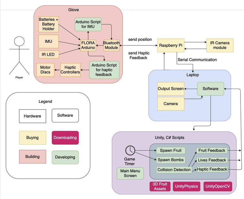
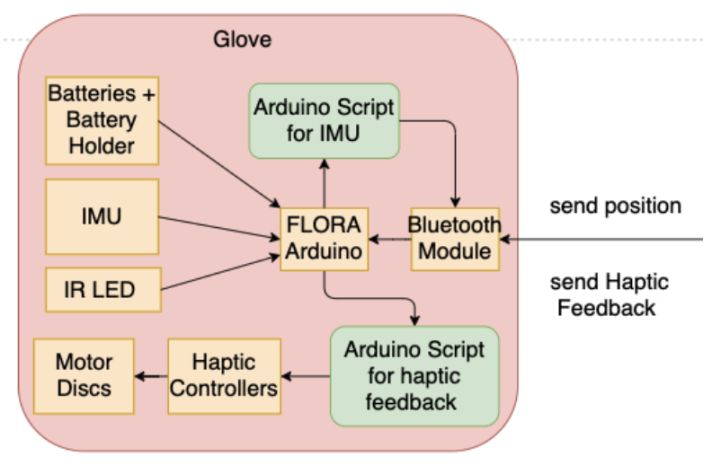
18-500 Design Report: 03/17/2021 2

 III. ARCHITECTURE AND/OR PRINCIPLE OF OPERATION
 The main component of the glove controller (Fig 1.) is the
wearable FLORA Arduino. For tracking the position of the
glove, we are using a combination of Infrared LEDs and an
Inertial Measurement Unit (IMU) to send positional data
directly to the FLORA. The IR LEDs are being tracked by the
Infrared Camera Module on the RaspberryPi which is
connected to the Laptop. The FLORA will have two scripts for
communicating with Unity through the Arduino Bluetooth
module. The first script is for sending the positional data, and
the second is for receiving feedback from the laptop. Depending
on what this feedback value is, a Multiplexer will turn on the
appropriate Haptic Motor Controller, which itself controls a
Vibrating Mini Motor Disc. In this manner, the player will
receive different vibrations depending on the current game Fig. 1. Zoomed-In Glove Schematic.
state. Finally, the glove controller also has a battery holder so
that it can be wireless. This is critical for convenience and
usability since we want this controller to replace the current
Augmented and Virtual Reality controllers that exist at the
moment.
 In between the Hardware glove controller and the Unity
Software (Fig 2.), the IR LEDs on the glove will be tracked by
the IR Camera Module which is attached to a RaspberryPi. The
RaspberryPi can then transmit this positional data to Unity with
Serial Communication. It can also receive haptic feedback from
the game and send this back to the FLORA on the glove. We
will have at least one camera pointed at the glove so that the
IMU can also track its position because we are using a
combination of IR LEDs and an IMU. The second camera,
which is not part of our MVP, could be used to play the game
in a more immersive experience. If the player chooses to point
this camera in their living room or anywhere they desire, they
could play Augmented Reality Fruit Ninja on the background
that they choose.
 The Software diagram (Fig. 3) shows an arrow coming into Fig. 2. Zoomed-In RaspberryPi + Laptop Schematic
the block on the left. This is the positional data being sent from
the glove controller. Since Unity has Bluetooth communication,
it is able to send and receive data to/from the Arduino’s
Bluetooth module on the glove. This positional data needs to be
interpreted and converted into a mouse on the screen. From
there, Unity can simply assume that the mouse is the input for
the Fruit Ninja game. We can then do some Collision detection
with the mouse and the other objects in the game (fruits, bombs,
special fruits/bombs). For both Fruit and Bomb objects, we can
keep track of their position, their name or type of fruit/bomb,
the number of points that they are worth, and whether they have
been cut or not. The game keeps track of an array of fruits and
bombs that are on-screen and have not been cut. The game Fig. 3. Zoomed-in Software Schematic
physics in Fruit Ninja are relatively simple: the fruits and
bombs spawn at the bottom of the screen and then travel in an
arc motion, first up to the top of the screen and then back down.
The game timer is in charge of actually spawning these objects
and will spawn more over time as the game progresses. Finally,
our game will also have a Main Menu.
18-500 Design Report: 03/17/2021 3

Fig. 4. Complete Block Diagram

 The figure above (Fig 4.) shows the Block Diagram as whole,
which is a combination of Figures 1, 2, and 3: the glove C. IR LED – RaspberryPi Interface
controller, the RaspberryPi and cameras, and the Unity Fruit Infrared Cameras connected to the Raspberry Pi will track
Ninja Game. the IR LED position in real time.
 IV. INTERFACES D. RaspberryPi – Laptop Interface
A. LED-Laptop Interface The RaspberryPi sends the following data to the laptop:
 1. Processed IMU positional data
 The Laptop camera will capture video of the surrounding 2. Processed IR LED positional data
environment and OpenCV computations will track the position
of the LED. The laptop sends the following data to the RaspberryPi:
B. Arduino-RaspberryPi Interface 1. Haptic feedback signal to trigger Arduino Motor
 The bluetooth serial module connected to the arduino Controllers
periodically sends the IMU accelerometer readings to the E. Unity – Laptop Interface
Raspberry Pi. The laptop provides Unity with the processed glove
 The Raspberry Pi sends the haptic feedback signal to the position. Unity sends the haptic feedback signal to the laptop.
arduino when the motors need to be triggered.
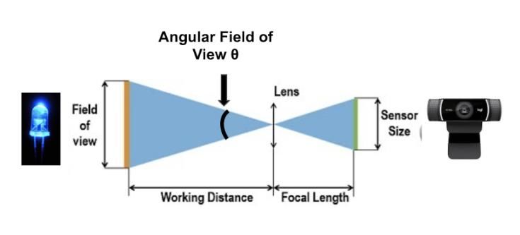
18-500 Design Report: 03/17/2021 4

 V. DESIGN TRADE STUDIES 2.5 2.54762789 1019.051156
 In order to ensure an ergonomic system, the glove tracking 5 5.095255779 2038.102312
should have a high accuracy and minimal latency. In order to
achieve this requirement, the following approaches were Since the camera provides us with 1280x720 pixels all
considered. measurements up to a working distance of 1.5 meters would be
 possible, however, the accuracy along the y-axis would reduce
A. Using colored LEDs with OpenCV: when working distance ⩾ 1.5 meters. This approach also
 This approach consisted of tracking the specific color of the involved 3 OpenCV operations on every frame which would
LED and involved resizing each frame, blurring it, converting take ( ℎ ∗ ℎ ) runtime and lead to poor latency.
it to HSV and then applying a mask for the specific LED color.
The accuracy of this approach depends on the field of view of
the camera, and number of pixels used per feature. In order to B. Inertial Measurement Unit (IMU)
verify if this solution would meet our accuracy requirements we
used the following figure: The IMU consists of an accelerometer and gyroscope unit
 that can be used to track the glove position in 3-D. The
 accelerometer can provide 3-D acceleration measurements and
 accelerations due to motion am, a gravitational component ag
 and error ε [6]. This provides us with the following equations:

 Assuming initial glove velocity is v(t1), the glove velocity at
 an instant of time t2 can be calculated by accumulating
Fig. 5. Camera Field of View
 acceleration changes [6].
 Based on the figure, the following equations were derived to
calculate the minimum required sensor resolution:

 Similarly, the displacements s(t), can be estimated by
 accumulating changes in velocity.

 Assuming we are using a MacBook 2020 Laptop we assumed
the following values:
 Assuming the following values: After testing the IMU on our subsystem we found poor
 Variable Value accuracy as compared to the LED due to the following reasons:
 Minimum Working Distance (meters) 0.5 • Double integration of acceleration to find new
 [3] positions. This implies that any errors in
 Maximum Working Distance (meters) 2.5 acceleration measurements will increase
 [3] exponentially.
 Sensor Resolution (pixels x pixels) [4] 1280x720=928,800 • Position error accumulates because the new position
 Sensor Angular Field of View 54° depends on the initial position.
 Pixels per feature 2 • Errors associated with IMU hardware itself.
 Size of LED to track (millimeters) [5] 5

 Using the following fixed values, the table below C. Infrared LED and Receiver
demonstrates the minimum sensor resolution required to These components help accurately track the position of the
accurately track a 5mm LED based on variable working glove in the x,y,z planes using the setup outlined in Figure 6
distance. (below):
 Working Distance Linear Field of Minimum Sensor
 (meters) View (meters) Resolution (pixels)
 0.5 0.5095255779 203.8102312
 1 1.019051156 407.6204623
 1.5 1.528576734 611.4306935
 2 2.038102312 815.2409247
18-500 Design Report: 03/17/2021 5

 VI. SYSTEM DESCRIPTION
 The overall system is composed of multiple subsystems
 which, combined, allow for the project to achieve the desired
 goals for a smooth gameplay experience.
 A. Bluetooth Communication Module
 Haptic feedback will be achieved via a Bluetooth Low-
 Energy (BLE) connection to the Raspberry Pi. The Raspberry
 Pi is the communication bridge between the computer running
 the game and the glove itself. To describe the flow of data for
 the haptic feedback event, first the Unity game encounters an
 event which it wishes to trigger haptic feedback. The game then
Fig. 6. Infrared LED – Camera Setup calls a function which invokes a script to send a serial message
 (see Section VI.B) to the Raspberry Pi, which triggers the
 The IR LEDs provide a radiometric power of 530MW,
 Raspberry Pi to send a Bluetooth signal to the Arduino FLORA,
wavelength of 850nm. The receiver resolution of 1080x720
 which receives it and triggers the rumble effect. The Adafruit
pixels for video provides accuracy similar to using a laptop
 BLE library is used to handle Bluetooth communication on the
camera for color detection (should provide required accuracy
 Arduino Flora. Adafruit provides drivers which will be used to
up to 1.5 meters from camera). Using IR tracking provides the
 interface with the FLORA Bluetooth module [7]. On the
following benefits over the previously discussed approaches:
 Raspberry Pi, the standard socket library is used to interface
 • Optical tracking is less susceptible to background
 over Bluetooth. The protocol that drives the Bluetooth
 noise. Color tracking is susceptible to background
 communication defines the following messages:
 colors within the LED color range.
 • “init” – sent by the RaspberryPi, and necessitates a
 • Since the input frames will only consist of the
 response of “init:true” within 2.5 seconds if the
 Infrared signal there will be 1 filter applied to every
 FLORA is in working order
 frame. A reduction in computation requirements
 • “rumble” – sent by the RaspberryPi, and expects the
 will ultimately lead to a reduction in latency.
 FLORA to trigger a rumble effect on the glove
 B. Serial Communication Module
 The Raspberry Pi communicates via a serial connection with
 the computer. The communication protocol is as follows: For
 Comparison of Proposed Solutions both sides of the communication, a message is defined as a
 sequence of bytes followed by a line separator. A message is a
 Metric OpenCV + IMU IR LED + loosely-defined and extensible sequence of bytes that controls
 LED Receiver an effect on the receiving end of the message. One such
 Resolution 1280x720 - 1080x720 message is the “init\n” message sent by the PC to the Raspberry
 Accuracy Can provide Poor Can provide Pi. It expects a response of “init:true\n” or “init:false\n” within
 required accuracy, required 5 seconds, where a timeout implies a failure to connect. A value
 accuracy up to needs to be accuracy up of true denotes that the Raspberry Pi was successfully able to
 1.5 meters recalibrated to 1.5 meters communicate with the Arduino FLORA, and a value of false
 from camera often from camera means that the communication check failed. After initialization
 2-D Yes Yes Yes has succeeded, the PC can send a message of the form
 Tracking “rumble\n” to the Raspberry Pi at any time in order to cause a
 3-D No Yes Possible with rumble effect. The Raspberry Pi outputs the calculated
 Tracking two receivers positional data via messages of the form “x:3, y:7, z:-9\n”. The
 Input If background High Low pySerial Python library is used to handle the sending and
 Signal consists of receiving of these messages on both the Raspberry Pi and host
 Noise colors similar machine [8]. To facilitate communication between the game
 to glove LED environment and the Python script managing the serial
 Latency High latency, Low Low latency, connection, a simple library is provided for the Unity game.
 3 filter applied latency, 1 filter This library exposes a function Init() which starts the Python
 to each frame minimal applied to script and connects to its socket. An event handler is registered
 computation each frame during the Init() process which is invoked when new position
 data is available. A Rumble() method is also exposed which
 sends data over the Python socket to trigger the rumble effect
 on the glove.
18-500 Design Report: 03/17/2021 6

C. Infrared Position Module Arduino FLORA.
 Infrared Position tracking is the main module responsible for
determining the glove’s position. It performs this via an infrared VII. PROJECT MANAGEMENT
camera on the Raspberry Pi which follows an Infrared LED A. Schedule
mounted on the tip of the glove. The Raspberry Pi handles the
 It is important to reiterate the primary focus of our project:
image processing and transformation of raw image data into x,
 the glove controller. Thus the first half of the project, and of the
y, and z position mappings. To accomplish this, a calibration
 semester, is dedicated to building the glove and testing it. We
step will have to be performed that identifies the boundaries of
 need to make sure that the Bluetooth communication between
the user’s gameplay space. The calculation for mapping
 the Arduino and the RaspberryPi works. To test this, the
coordinates from the infrared camera to game coordinates will
 Arduino must be able to send the positional data (from the IMU
be performed by this module on the Raspberry Pi. This allows
 and the IR LED) to Unity and receive the feedback that it sends
for the data which is transmit over serial to the PC to be pure
 back based on the game state. Once all parts on the glove have
positional coordinates that it can access immediately with no
 been tested and we are sure that the back and forth
calculation. The design intentionally leaves open the potential
 communication functions correctly, then we can move onto the
to add an additional Raspberry Pi and camera module which
 Software side of the project. This includes the base game
tracks the IR LED from a different perspective, allowing for 3D
 engine, collision detection between the fruit/bomb objects and
depth sensing. Absent of this upgrade, the z coordinate will
 the mouse, game physics, and any other functionalities for the
always remain constant at 0.
 Fruit Ninja game.
D. Game Module
 B. Team Member Responsibilities
 We intentionally designed our system such that it is not
 Due to the circumstances that arise from this global
tightly integrated into the game code. The game is merely
 pandemic, this course is being taught remotely. For this reason,
treating the glove system in a black-box way, where it does not
 it makes sense to have one member of our group in charge of
deal with the data processing itself. It simply expects the
 assembling the Hardware so that we don’t need to each build a
positional data to arrive over a socket connection, and displays
 glove. So, all of the parts have been ordered to Arthur’s house,
the game objects accordingly. Therefore, a different game could
 but the three of us will meet on campus to build it. Then, all
make use of our glove without re-engineering the underlying
 three of us will be focused on the back-and-forth
components. The Fruit Ninja game is intended to be a
 communication between the glove and Unity (positional data
demonstration of using the glove system, and as such is
 and haptic feedback). While Arthur is testing the functionality
intentionally designed to not be tightly integrated. It has full
 of the glove, Ishaan and Logan will test the Bluetooth
access to the glove system via the scripts and socket connection,
 Communication between Unity and the FLORA Arduino. Then,
but the details for how position is sensed and tracked are
 Ishaan and Arthur will write Collision Detection algorithms in
irrelevant to the game developer. This is crucial for portability
 Unity while Logan builds the basic game engine for Fruit Ninja.
of the glove system. For the Fruit Ninja game implementation
 Once we have the skeleton of the game, the three of us will
specifically, the game begins by performing a setup process as
 focus on the game physics and some last details for certain
defined by our Unity API, which confirms all components are
 game functionalities.
connected. During the initialization, the player will be asked to
move their hand to draw the corners that define the border of C. Budget
where they will be playing. An on-screen prompt explains this To date, we have purchased all of the components outlined
process. After initialization has been completed, the game in our design, and almost all components have arrived. There
begins, and motions of the player’s hand will swipe and slice are a number of components that have been ordered and arrived,
fruit which float into the screen. The game uses the Unity but may not make it into the final system. This was a conscious
Physics Package to simulate the effect of fruit being tossed onto decision, however, since the total cost for our components was
the screen and falling in a realistic way, under the effect of always expected to be relatively low, so wasted budget was not
gravity [9]. a large concern. The breakdown of components and budget is
E. Haptic Feedback Module appended in a table at the end of this report (Figure 8).
 The haptic feedback module depends on the previous D. Risk Management
modules for communication, and builds upon them to provide a Already this project has faced a number of unexpected
rumble effect on the glove. The rumble effect is achieved via a deviations from the initial idea. Some strategies we have made
simple vibrational motor disk. This motor disk is controlled by to reduce risk are inherent to the modular design of the
the Adafruit haptic motor controller, which communicates with system, and our plan to frontload work on the physical aspects
the FLORA over I2C [10]. When the FLORA receives a of the project, while leaving software finishing touches to the
Bluetooth message to trigger a rumble, it sends an initialization end. With our initial design, we wanted to track position via a
sequence followed by a simple rumble code as documented on laptop webcam and an RGB LED. We then explored swapping
the Adafruit website. The power for the motor controller is this method for an IMU sensor, however, preliminary research
connected in parallel with the 3.3V power supply for the showed that since IMUs can only detect acceleration, position
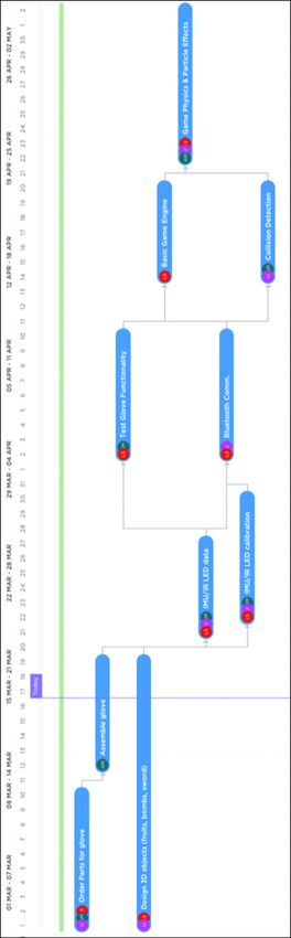
18-500 Design Report: 03/17/2021 7

is achieved by a double integration. This means that any error
would be squared, so drift would be quadratic, and unsuitable
for our purposes. Therefore, our current plan is to use an
infrared LED and camera for position tracking. For another
layer of risk mitigation, if the IR system does not achieve our
required benchmarks for precision, we can add the IMU
module back on the glove to assist with position tracking,
while using the IR system to gain a reference point. We are
capable of making this pivot if necessary because the
Bluetooth module is designed to be extensible and transmit
data as needed to the Raspberry Pi receiver box.

 VIII. RELATED WORK
 The main commercial product that relates to our system is
the CyberGlove by CyberGlove Systems, which is a company
with over 20 years of work in building motion and finger
tracking gloves. As such, their products are $30,000 per glove
and incorporate advanced sensors [11]. Researchers such as
Johnny Lee have successfully used the infrared camera
bundled in the Wii remote to track infrared-emitting objects in
a room [12]. This approach is similar to our plan to use an IR
tracking system. One academic approach that makes use of an
IMU system for finger tracking was explored by The Control
Systems Group in Berlin [13]. By using high quality 9DOF
IMU sensors, the researchers were able to track finger
movements within an error of +/- 3% over a 15-minute period.
The advantage of IMU approaches is the lack of a dependency
of line of sight. This is not a design constraint of our project,
but past work on stabilizing IMU position data via point of
reference dead reckoning could allow us to achieve higher
quality data.

 Fig. 7. Schedule
18-500 Design Report: 03/17/2021 8

 IX. REFERENCES [13] Christina Salchow-Hömmen et al. (19 January 2019).
 Retrieved 17 March 2021.
 https://www.ncbi.nlm.nih.gov/pmc/articles/PMC63392
 14/
[1] Prakash Haridas (December 2020). How Fruit Ninja
 Achieved 1 Billion Downloads Over 5 Years.
 Retrieved 17 March 2021.
 https://www.referralcandy.com/blog/fruit-ninja-
 marketing-strategy/

[2] Richard Leadbetter (5 March 2018). What Went Wrong
 with Kinect? 17 March 2021.
 https://www.eurogamer.net/articles/digitalfoundry-
 what-went-wrong-with-kinect

[3] UNITED States Department of labor. (n.d.). Retrieved 18
 March 2021
 https://www.osha.gov/SLTC/etools/computerworkstati
 ons/components_monitors.html

[4] Hiner, J. (2020, March 18). Apple's new 2020 MacBook
 air left out one important upgrade. Retrieved 17 March
 2021, from https://www.cnet.com/news/apples-new-
 2020-macbook-air-left-out-a-key-upgrade-for-people-
 working-from-home/

[5] Cooper, T. (n.d.). All about leds. Retrieved 17 March
 2021, from https://learn.adafruit.com/all-about-
 leds/what-is-an-led

[6] Trung, L. H. (2019). Retrieved 17 March 2021
 Https://euroasia-science.ru/pdf-arxiv/the-
 controllability-function-of-polynomial-for-descriptor-
 systems-23-31/

[7] Adafruit FLORA Bluetooth LE (12 May 2015). Retrieved
 17 March 2021. https://learn.adafruit.com/adafruit-
 flora-bluefruit-le

[8] pySerial (22 November 2020). Retrieved 17 March 2021.
 https://pypi.org/project/pyserial/

[9] Unity Physics (2020). Retrieved 17 March 2021.
 https://docs.unity3d.com/Manual/PhysicsSection.html

[10] Adafruit DRV2605L Haptic Controller Breakout (17
 December 2014). Retrieved 17 March 2021.
 https://learn.adafruit.com/adafruit-drv2605-haptic-
 controller-breakout/downloads

[11] CyberGlove Systems. Retrieved 17 March 2021.
 http://www.cyberglovesystems.com/cyberglove-iii

[12] Johnny Lee (2008). Retrieved 17 March 2021.
 http://johnnylee.net/projects/wii/
18-500 Design Report: 03/17/2021 9

 Fig. 8. List of Parts for Budget
You can also read