Team Description Paper robOTTO RoboCup@Work 2021
←
→
Page content transcription
If your browser does not render page correctly, please read the page content below
Team Description Paper robOTTO
                RoboCup@Work 2021

   Christoph Steup, Martin Seidel, Leander Bartsch, Inga Brockhage, Nils
   Harder, Niklas Harriehausen, Gerhard Jörges, Anna Klobertanz, Adrian
Köring, Franziska Labitzke, Wiebke Outzen, Hauke Petersen, Anton Striecks,
     Fabian Richardt, Jurek Rostalsky, Jakob Rühe, Nele Traichel, Sanaz
               Mostaghim, Arndt Lüder, and Stephan Schmidt

            Otto-von-Guericke University, 39106 Magdeburg, Germany
                          {steup,maseidel}@ovgu.de,
                     WWW: http://www.robotto.ovgu.de/

      Abstract. Team robOTTO is the RoboCup@Work League team of the
      Otto-von-Guericke University Magdeburg, formerly participating in the
      Robocup Logistics League since its founding in 2010. In our team, we
      combine the expertise from Computer Science, Electrical and Mechanical
      Engineering to solve @Work’s unique challenges while fostering knowl-
      edge exchange between the different leagues.

      Keywords: RoboCup@Work, robOTTO, RoboCup2019

1   Introduction
robOTTO was founded as a RoboCup Logistics[5] team in 2010 by nine stu-
dents from different fields, enabling exchange of knowledge and views between
the members. After achieving second place 2010 in Singapore the team continued
to attend following RoboCup competitions with further successes in 2012 (4th
Place) and 2013 (2nd Place). The change from RoboCup Logistics to @Work
League helped to broaden the expertise of the team and in fact eased the
Crossover Challenge[9] at the @Work League, resulting in a first place at world
cup in Leipzig 2016. In 2012 a first attempt at a second competition resulted in
an 8th place in the 2D Soccer Simulation League. With regards to broad rule and
equipment changes in the Logistics League in 2015 we decided to participate in
the @Work League[4], as the Computer Science Faculty already had some expe-
rience on the KUKA youBots[1], thus providing a pool of experienced students
and easy integration into courses and research projects. The team competed in
the world cup 2015 in China and reached 6th place followed by the world cup in
Leipzig in 2016, where we scored 4th. 2017 was very successful for us, resulting in
a third place at the GermanOpen and a second place at the world cup in Japan.
In Montreal (Canada) the team achieved the first place in the Arbitrary Surface
Challenge. In the last WorldCup in Sydney (Australia) the team achieved the
Vice-World-Champion title again. In 2020 no real world cup was done and the
team achieved a best-presentation award in the Virtual RoboCup Asia Pacific
Open (VRCAP).
2
2 Team Structure
Task Name Field / Role
Sanaz Mostaghim Responsible Professor
Arndt Lüder Liason to Mechanical Engineering
Stephan Schmidt Liason to Mechanical Engineering
Organisation Christoph Steup Team Leader
Martin Seidel Co-Team Leader
Anna Klobertanz Electrical Engineering
Nils Harder Electrical Engineering / OC Member
Navigation
Niklas Harriehausen Mechanical Engineering
Nele Traichel Computer Science
Gerhard Jörges Electrical Engineering
Hardware Leander Bartsch Electrical Engineering
Inga Brockhage Electrical Engineering
Manipulation Hauke Petersen Mechatronics
Adrian Köring Computer Vision
Recognition Jakob Rühe Electrical Engineering
Anton Striecks Medical Technology
Wiebke Outzen Computer Science
Fabian Richardt Computer Science
RobotCoordination
Jurek Rostalsky Mathematics
Franziska Labitzke
Table 1. Overview of robOTTO team members by task and field of studies or role
Currently, the team consists of 16 active members, whereas the professors are
not involved in the development and only provide guidance and organizational
support. Since the team is mainly composed of students, who leave the team
after finishing their studies, we have a young and dynamic team of students.
Depending on the new members and their backgrounds, the team can largely
benefits from a diverse set of expertise. The current team members provide a
large spectrum of topics from cybernetics and computer science to electrical
engineering to the team as shown in Table 1. The new students provide new
ideas and also new challenges to the team. Currently, the new members try to
ease the use of the robot in the competition to minimize human errors, as they
found the work-flow quite difficult.
3 Robot Description
The standard KUKA youBot does not provide any sensory equipment. Modi-
fication were necessary to use the robot in the @Work league. To minimize effort
and maximize results most of the additions are COTS, used in the robotics
community. Our modification relate to the sensory equipment consisting of an3
additional camera and two laser scanners and to the manipulation system ex-
tended with a specialized gripper. Additionally, we switched to a more powerful
PC.
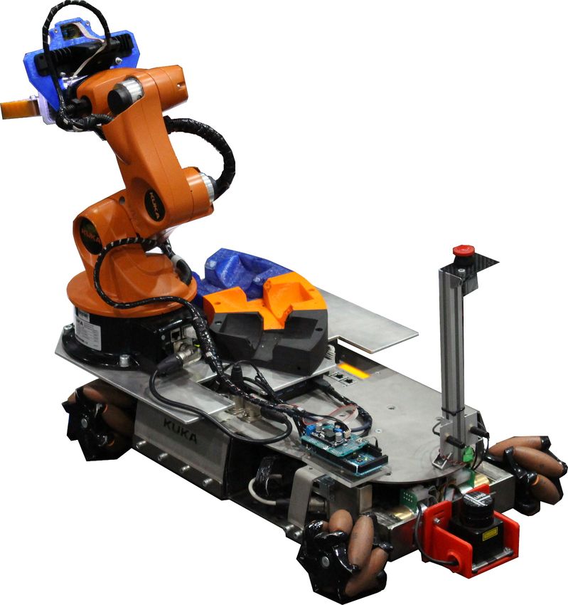
Fig. 1. Modified KUKA youBot
3.1 Changes to the standard Platform
Camera We use an Intel RealSense RGB-D camera which provides registered
point clouds as well as an RGB-D image. Currently, we focus on the colour data
for recognition and use the depth image as a highly flexible distance sensor.
Around the lenses and projectors of the RealSense we mounted an oval-shaped
ring of LEDs to improve lighting conditions and enable a reliable object detection
and classification. During navigation the RealSense camera is used to detect
barrier tape.4
Gripper The objects of the @Work league have varying shapes and sizes. After
preliminary tests we observed that the normal metal gripper on the KUKA
youBot cannot reliably handle many of these objects. Our current gripper is
based on an custom 3D-Printed mount using servos by Dynamixel and Finray-
fingers by Festo, which are controlled by an Arduino. Current development
focus on correctly identifying and handling error cases like the loss of an object.
Additionally, we aim to improve the grasping of not perfectly aligned objects.
Computing and Connections An Intel Core i7 NUC was fitted into the
robot as a replacement for the original Atom-based computer to enable more
complex algorithms for navigation, path planning and task optimization. Addi-
tionally, an Arduino was fitted to the chassis to integrate various embedded
components like servos, time-of-flight distance sensors and LEDs. The hardware
and software architecture is modularized through defined interfaces to provide
a stepping stone for students inexperienced with programming to experiment
without needing the whole development stack used on the main robot.
Laser Scanner Mounting Brackets The team uses Hokuyo URG-04LX
laser scanners. These provide appropriate distance measurements in a 240◦ ra-
dius with a maximum distance of 5.5 m. A reliable localization is possible if the
laser scanners are exactly parallel to the ground. To this end the team designed
reliable, adjustable mounting brackets, which were 3D printed by the team to
prevent tilt errors even at the edge of the scanner’s measurement range and
shield the expensive sensors in the case of accidental collisions.
Replacement of the Upper Case For the time being, the upper case of the
youBot is a bended steel plate, that’s connected to the bottom panel. On the top
there are recesses for the display, various ports (USB, LAN, power connection)
and threaded holes to mount the Arm. Beneath the steel case is the electronics.
We have extended the upper case with an aluminium plate. It provides more
place for an inventory and gives the opportunity to offset the arm to the side,
see Figure 1.
The newly designed and manufactured upper case completely replaces the
old top cover of the YouBot. It provides the option to access the underlying
electronics easy, while extending the space inside the robot. This enables another
Intel Core i7 NUC, the power supply of the grippers and our USB3 hub to be
stored inside the robot, see 3.1. Furthermore, the inventory, emergency switch
and arm has pre-build mountings on the new case. Thanks to multiple mounting
holes the inventory can be offset and additional parts can be added easy to the
surface. However, integration and testing of the new cover is currently in progress
and it remains an open question if it will be used in this years’ competitions.
Lithium Polymer-based Battery System The original lead-based batteries
of the YouBot have two major drawbacks. Firstly, they are incredibly heavy,5 which increases the transportation cost when flying. Secondly, their contained energy is rather scarce compared to the power necessary for all the components. Currently our bot lasts at max 30 minutes, which is quite limited. Because of these reasons we decided to switch to Lithium-Polymer-based batteries. But in- stead of using single cells, we uses Bosch tool batteries, which are widely available and raise no suspicion at the airport. To this end, we integrated two of-the shelf buck-boost DC-DC converters for 12V and 24V as well as a customly designed PCB to hold voltage and current measurement as well as emergency switches to cut the different power rails. The current setup uses two batteries in parallel, which allows us to Hot-Swap the batteries without powering down and up the bot. Because of the ongoing Corona-Pandemic we could not test the endurance of the new system. 4 Software Architecture In this section we want to describe the main software components and how they interact. We use the Robot Operating System (ROS)[7] in the Melodic version running on Ubuntu 18.04 LTS. The main advantages are the commu- nication abstraction and the great number of easy-to-use debug tools. 4.1 Overview Fig. 2 shows the interaction of our software components. They are described in detail in the following sections.
6

                                       @Work
                                       RefBox

                                     Optimizer

                                       State
                                      Machine

         Navigation                                         Manipulation
                                     RTT State
           State                                               State
                                      Machine
          Machine                                            Machine

                Barrier Tape                            Gripper
                                     Deep Vision
                 Detection                              Control

    move base             AMCL                                       MoveIt!

     KUKA
                      Hokuyo Lidar          Realsense         Gripper
     YouBot

Fig. 2. Overview of the main software components of the robOTTO @Work framework.
7
State-Machine and Optimizer Core elements of the robot software architec-
ture are the optimizer and the state-machine, which are responsible for coordi-
nating the other modules of the robot like vision, navigation and arm movement.
The transportation tasks, which the robot has to fulfil, are generated by the
@work referee box of the league and transferred to the robot. On the robot side
the receiver node is used for processing and forwarding those messages to the op-
timizer. The optimizer searches for a sequence of transport tasks which reaches
the maximum score within the time limit. Subsequently it generates SubTasks
as an input for the state machine. Typical SubTasks are picking up an object,
placing an object or moving the robot to a workstation.
The state machine contains a logic for every SubTask. The logic determines
a graph of parametrised actions which are necessary to perform the SubTask.
Common actions are the MoveAction, ArmAction and VisionAction. They con-
trol the sub-state machines of the corresponding robot modules. For instance a
simplified PickLogic consists of following actions:
1. ArmAction moves the arm to the pose for barrier tape recognition.
2. MoveAction moves the robot to a specified workstation.
3. ArmAction moves the arm to the pose for object recognition.
4. DetectAction looks for the specified object on the workstation.
5. ArmAction picks up the object which was localized by the vision and place
it in the inventory.
Because a reliable state machine is critical for the success of a robot performance,
it is one of the most intensively unit tested modules of the robot.
World Model The world cup 2017 in Leipzig showed that the complexity
of the tasks and the environment is difficult to handle in our current software
architecture. To incorporate additional information on the state of the arena
or the robot lots of changes to code and interfaces were necessary. To mitigate
this engineering issue, we decided to manage the information on the world in
a central component. The resulting world model component allow us to store,
track and replay changes to the robots and the arenas state. Additionally, we
add support to add and modify the data in the world model of a specific task
and visualize it. The major benefit of this approach is the stability of interfaces
between our functional SubTask components, as well as the centralized point
for team members to add and request information on the world. Finally, the
visualization tool gives us better insights into the robots current behaviour and
choices to ease debugging.
Deep-Learning-based Vision - Deep Vision We currently only use 2D
images for object detection even though the realsense also provides 3D data. Our
object detection system is based on the Tensorflow Object Detection API. We
created a custom bootstrapping and augmentation system to generate additional
training data. The major work in this systen was the manual generation of
training data. To ease the process we developed a custom tool to check the8
detection and classification output and generate manually corrected training
samples. To only addition to the original detection API is an additional object
orientation detection code to also output a 2D rotation of the object on the
workstation.
Path Planning for Industrial Robots The navigation of industrial robots
has to be developed with multiple competing influences in sight, as fast move-
ment and collision avoidance are both critically important to successfully par-
ticipate in RoboCup@Work. Other factors are more subtle, like predictability
of behaviour and easy maintenance and adaptability. The last two points are
especially important in the context of RoboCup as a competition of students,
where team members and responsibilities switch regularly and members have to
be able to familiarise them self with the code, often on a short notice.
The current navigation stack used by robOTTO supports two different ap-
proaches. The first approach uses the DWA-Planner (Dynamic Window
Approach)[3] which is open source code and the standard planner for holo-
nomic platforms in ROS. Since, it is quite complex with many configurable
parameters we use a slightly modified parameter-set which was made available
publicly by the b-it-bots team for usage with the KUKA youBot.
The second approach is a minimal implementation of a local Planner which
relies on the global planner for object avoidance to keep the complexity and fea-
ture duplication down. It was developed after preliminary tests with the DWA-
Planner showed unpredictable and often oscillating behaviour depending on a
multiple factors like CPU load and floor conditions.
Integration of the MoveIt! Trajectory and Kinematics Stack The pre-
viously used kinematics stack for the manipulator used by the team, SAMIA,
was built by former member Stefan as a by-product of his Master’s Thesis and
subsequently adapted for the @Work competition. But with Stefan gone we now
face problems maintaining and extending the codebase. This led to the decision
to abandon our own stack in favour of MoveIt! [2]. MoveIt! is an open-source
motion planning framework originally developed by Willow Garage, which unifies
motion planning kinematics, collision checking and dynamic three-dimensional
environment representations. As it was initially developed to be used with ROS,
it offers a high degree of integration with existing packages and tools, such as
RViz. The stack’s incorporation into our code, as well as the creation of the
arm-state-machine Figure 2 and interfacing with our main state machine was
done by Hauke. Since then it proved to be a viable alternative to our previous
solution and had successfully been used at GermanOpen 2016 in Magdeburg
and RoboCup 2016 in Leipzig. One of the stack’s issues on our platform was
the calculation time required to generate a valid movement trajectory. For this
purpose we have developed a ROS package which allows caching static trajec-
tories (e.g. when placing an object in one of the inventory slots) and integrate
them in dynamic trajectory paths to speed up the calculations. Currently, we9
are working on a feature allowing quick movements within a small area with-
out time-costly kinematic calculations, an option much needed for the upcoming
implementation of the Precision Placement Task.
Barrier Tape Detection The Barrier Tape Detection is asked to spatially
locate barrier tape strips given a camera image and position.
To achieve this, we first detect the barrier tape in the image. This is done
using a semantic segmentation on the camera image also used for object detection
and recognition. However, in this case a convolutional neural network is used,
which combines the task of filtering, segmentation and recognition. We used
Tensorflow to implement the network and train it. The output of the network
is an image of white pixels, where the barrier tape was detected. The training
samples are generated using images of the used barrier tapes in the competition
overlayed on various background images and lighted by Blender. To get the
world coordinates of the barrier tape we cast rays from the camera through the
white pixels in the mask into the scene and find intersections with the ground
plane. All such intersection points finally form the resulting point cloud, which is
fed to the navigation stack as an additional sensor. The only manually configured
part of the Barrier Detection is the calibration of the mapping of the 2D camera
coordinates to the 2D map coordinates of the navigation.
4.2 Future Software Components
Fully Integrated Rotating Table Operations Changes in the RuleBook of
the league [6] needed new behavior to handle grasping from the rotating table.
The team already created new behavior including new detection mechanisms
to handle the rotating table. However, the current approach is a cross-layer
approach, which breakes the normal flow of control between the system compo-
nents, as described in Section 4. Consequently, the current software works for
the designated rotating table task as specified in the RuleBook [6]. To enable the
rotating table operations also in normal tasks like the FINAL, an integration of
the behavior is necessary, which needs a generalization of the current software
architecture.
Graph-based Visual State-Machine Currently, the behavior of the robot is
encoded in three state-machines, which control the actions necessarz for navi-
gation and manipulation as well as the general behavior to pick-up and place
objects. However, these encoding are based on manually written C++-Code.
This code is cumbersome to modify and also fails easily. However, in competi-
tions the ability to quickly modify the state-machine is crucial. Consequently,
we currently try to move our state-machines to FlexBE [8] to enable easz modi-
fications and integrated testing of the encoded behaviors.10 5 Conclusion With the influx of new team members and the continued participation by last years members we are cautiously optimistic that we will be able to build upon the work done last year. Expected changes to the rules of the competition mandate some overhauls of components like PPT control and the Round-Table grasping and detection mechanism. The last participation left us with a code base solving most of the tasks of the @work league. This enables us to focus this year on testing and improving the robustness of the working solutions, while adapting them to the new rules. Acknowledgements We would like to thank Sanaz Mostaghim, Chair of Computational Intelligence for her support during the year and providing us with access to tools and the necessary facilities for storage and testing. The team and all former members would also like to thank Arndt Lüder for his engagement and support since our founding in 2010. References 1. Rainer Bischoff, Ulrich Huggenberger, and Erwin Prassler. Kuka youbot-a mobile manipulator for research and education. In Robotics and Automation (ICRA), 2011 IEEE International Conference on, pages 1–4. IEEE, 2011. 2. Sachin Chitta. Moveit!: an introduction. In Robot Operating System (ROS), pages 3–27. Springer, 2016. 3. Dieter Fox, Wolfram Burgard, and Sebastian Thrun. The dynamic window approach to collision avoidance. IEEE Robotics & Automation Magazine, 4(1):23–33, 1997. 4. Gerhard K Kraetzschmar, Nico Hochgeschwender, Walter Nowak, Frederik Hegger, Sven Schneider, Rhama Dwiputra, Jakob Berghofer, and Rainer Bischoff. Robocup@ work: competing for the factory of the future. In Robot Soccer World Cup, pages 171–182. Springer, 2014. 5. Tim Niemueller, Daniel Ewert, Sebastian Reuter, Alexander Ferrein, Sabina Jeschke, and Gerhard Lakemeyer. Robocup logistics league sponsored by festo: a competitive factory automation testbed. In Automation, Communication and Cybernetics in Science and Engineering 2015/2016, pages 605–618. Springer, 2016. 6. Asadollah Norouzi, Sebastian Zug, Deebul Nair, Christoph Steup, Marco Masannek, and Lucas Reinhart. Robocup@work 2021 - rulebook. https://atwork.robocup.org/rules/, 2021. 7. Morgan Quigley, Ken Conley, Brian Gerkey, Josh Faust, Tully Foote, Jeremy Leibs, Rob Wheeler, and Andrew Y Ng. Ros: an open-source robot operating system. In ICRA workshop on open source software, volume 3, pages 1–6. Kobe, 2009. 8. Philipp Schillinger. An approach for runtime-modifiable behavior control of hu- manoid rescue robots. Master’s thesis, Technical University Darmstadt, 2015. 9. Sebastian Zug, Tim Niemueller, Nico Hochgeschwender, Kai Seidensticker, Martin Seidel, Tim Friedrich, Tobias Neumann, Ulrich Karras, Gerhard Kraetzschmar, and Alexander Ferrein. An integration challenge to bridge the gap among industry- inspired robocup leagues. In RoboCup Symposium, pages 1–12, 2016.
You can also read