The application of duroplastic gap filling material DIAMANT MM1018 in preloaded bolted connections
←
→
Page content transcription
If your browser does not render page correctly, please read the page content below
DOI: 10.1002/stab.202200069                                         [Translated by DIAMANT Polymer GmbH]

                                                                                                                                                     AUFSATZ ARTICLE
Natalie Stranghöner, Lukas Makevičius, Anas Korbaj, Carsten Kunde                                                                    ARTICLE

The application of duroplastic gap filling material
DIAMANT MM1018 in preloaded bolted connections
Im Stahlbau werden Schraubverbindungen entweder aus                   The application of duroplastic gap filling material DIAMANT
Gründen der Tragfähigkeit oder der Gebrauchstauglichkeit              MM1018 in preloaded bolted connections
vorgespannt. Ein- und mehrschnittige Verbindungen in Brücken,         In steel construction, bolted connections are preloaded either
Funkmasten und Turmbauwerken von Windenergieanlagen                   for load-bearing capacity reasons or for serviceability reasons.
gehören zu den typischen Einsatzgebieten. Eine Spaltbildung,          Single and multi-section connections of wind turbines, offshore
hervorgerufen durch fertigungs- und montagebedingte                   plants, bridges etc. are typical application examples. Gap
Imperfektionen, stellt ein Risiko z. B. für das kontrollierte         formation, caused by imperfections due to fabrication and
Aufbringen des erforderlichen Vorspannkraftniveaus sowie zur          assembly, poses a risk e. g. for the controlled application of the
Vermeidung von Spaltkorrosion dar. Dies kann die Tragfähigkeit        required preload level as well as for the prevention of cavity
sowie die Dauerhaftigkeit der Verbindung erheblich                    corrosion. This can significantly impair the load-bearing
beeinträchtigen undsogar zu einem vorzeitigen Versagen                capacity and the durability of the connection and even lead to a
führen. Die Spaltbildung ist daher auf ein Minimum zu                 premature failure. Therefore, the formation of gaps must be kept
begrenzen, wobei DIN EN 1090-2 dazu Maßnahmen wie z. B.               to a minimum, whereby DIN EN 1090-2 provides possible
den Einsatz von Futterblechen vorsieht. Eine mögliche                 measures such as the use of packing plates for this purpose.
Alternative für den Ausgleich von Spaltenstellen                      Two-component reaction resin systems based on epoxy resins,
Zweikomponenten-Reaktionsharzsysteme auf Epoxidharzbasis              which are filled with special metallic materials to improve the
dar, die zur Verbesserung der mechanischen Eigenschaften              mechanical properties, are a possible alternative for gap filling.
mit speziellen metallischen Werkstoffen gefüllt sind. Im              Within the framework of the ZIM cooperation project “Bri-San-T
Rahmen des ZIM-Kooperationsprojekts „Bri-San-T –                      – DuroFüllSta”, systematic investigations were carried out into
DuroFüllSta“ wurden systematische Untersuchungen zum                  the use of the gap-filling material MM1018 of the company
                                                                      Diamant Polymer GmbH for use in preloaded bolted connections.
Einsatz des duroplastischen Spaltausgleichsmaterials MM1018
                                                                      In this contribution, experimentally determined slip factors as
der Firma Diamant Polymer GmbH in vorgespannten                       well as the expected preload losses overthe service life are
geschraubten Verbindungen durchgeführt. Im vorliegenden               presented and discussed.
Beitrag werden die experimentell bestimmten
Haftreibungszahlen sowie die zu erwartenden                           Keywords preloaded bolted connections; duroplastic gap filling material;
                                                                      slip-resistant connections; slip factor; preload losses
Vorspannkraftverluste vorgestellt.

Stichworte vorgespannte geschraubte Verbindung; duroplastisches
Spaltausgleichsmaterial; gleitfeste Verbindung; Haftreibungszahl;
Vorspannkraftverluste

1       Introduction                                                  A gap poses a direct hazard, e.g. for the controlled
                                                                      application of the required preload level or for the
In steel construction, bolted connections are preloaded               avoidance of crevice corrosion, and can therefore
either for reasons of load capacity or usability. Typical             significantly impair the load-bearing capacity and
application examples are single- and multi-shear                      durability of the preloaded bolted connection.
connections in (temporary) bridges, radio masts, etc.
                                                                      In order to avoid the consequences of gaps as far as
EN 1090-2 [1] defines requirements for the execution of               possible, EN 1090-2 limits a thickness difference of
steel constructions in order to guarantee sufficient load             separate components in preloaded applications to 1 mm
capacity, usability and durability. Although the necessary            and points out that smaller gap dimensions may be
technical competence and the corresponding technical                  necessary in corrosive environments to avoid crevice
equipment are usually available on the building site to               corrosion. Stiffeners are usually used in steel construction
meet the normative requirements, manufacturing and                    to compensate for gaps. However, care must be taken to
assembly-related imperfections cannot always be ruled                 ensure that the corrosion properties and mechanical
out, so that gaps can form between the bolted components.             strengths of the stiffener correspond to those of the
                                                                      adjacent components.

                                                                       © 2022 Ernst & Sohn GmbH, Berlin. Stahlbau 92 (2023), booklet 1, p. 27-38
                                                                                                                                                 1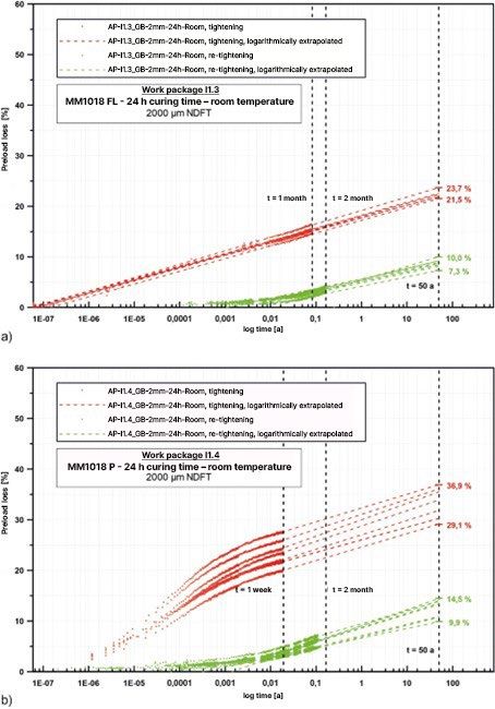
N. Stranghöner, L. Makevičius, A. Korbaj, C. Kunde: The application of duroplastic gap filling material DIAMANT MM1018 in preloaded bolted connections

In applications where a gap cannot be completely                                          2        Basic information about the
compensated by stiffeners, an alternative is to use, for                                           investigations carried out
example, two-component reaction resin systems based on
epoxy resin (if an appropriate approval is available).                                    If a friction surface class with the associated slip factor
                                                                                          cannot be assumed for the selected type of surface
These so-called hybrid connections are widely used in the
                                                                                          treatment of a slip-resistant connection on the basis of
aircraft industry, for example. In order to determine the
                                                                                          EN 1090-2, a standardised test method for determining
load-bearing behaviour of such connections, studies are
                                                                                          the slip factor according to EN 1090-2, Annex G is to be
carried out on an ongoing basis [2–12]. In the field of steel
                                                                                          used. The three-stage test method has already been
construction, however, the use of such materials, especially
                                                                                          presented in a great many national and international
in combination with bolted connections, is not yet
                                                                                          publications and will therefore not be explained in greater
common. The first studies of the use of a hybrid
                                                                                          detail at this point. In order to enable determination of the
connection (also referred to as a preloaded adhesive bond)
                                                                                          slip resistance of the gap filling material named, the test
in Germany were already carried out in the early 1960s [13,
                                                                                          method according to EN 1090-2, Annex G (among other
14] and were aimed at increasing the static load-bearing
                                                                                          things with modifications of the test specimens) was also
capacity of slip-resistant connections and their subsequent
                                                                                          applied within the framework of the ZIM cooperation
use in bridge construction. New studies by Wanner et al.
                                                                                          project "Bri-San-T – DuroFüllSta". Parameters such as the
[15], Glienke et al. [16], Afzali [17], Gerke et al. [18] and
                                                                                          gap width (2 mm, 5 mm, 10 mm), the curing time (24 h,
Boretzki/ Albiez [19] have also shown that the use of
                                                                                          7 d) and the assembly temperature (here: component and
adhesives can lead to an increase in the static slip loads as
                                                                                          outside temperature, low: 5 °C, high: 40 °C, room
well as slip factors. Thus, the structural adhesives
                                                                                          temperature: 20.5–23.1 °C) and their influence on the
investigated not only show great potential for possible gap
                                                                                          load-bearing behaviour of a slip-resistant connection were
compensation in general, but also open up new
                                                                                          randomly checked, wherein the reference configuration,
possibilities for the use of similar materials in preloaded
                                                                                          which has run through the entire test procedure according
bolted connections.
                                                                                          to EN 1090-2, Annex G, was defined for the respective
The metal polymer MM1018 from Diamant Polymer                                             product MM1018 FL and MM1018 P as a 2 mm gap width
GmbH is a two-component reaction resin system filled                                      (based on experience from previous applications) with
with special metallic materials than can be delivered both                                24 h curing time at room temperature. With regard to the
with a liquid consistency (MM1018 FL) and a pasty                                         renovation measures, e.g. in steel bridge construction, the
consistency (MM1018 P). The applicability of this metal                                   tests were also carried out on two possible surface
polymer has been proven by the general building authority                                 treatment methods:
approval (abZ) Z-3.82-2042 [20] in Germany and has
already been used in a variety of maintenance and repair                                  – GB: shot-blasted on all sides (angular blasting agent
applications.                                                                               made of chilled cast iron granulate, grain size: 0.6-
                                                                                            1.0 mm), degree of purity Sa 2.5 according to
Within the framework of the ZIM cooperation project "Bri-
                                                                                            EN ISO 8501-1 [21], surface roughness medium (G) of
San-T – DuroFüllSta/Development of a material model
                                                                                            approx. 99 µm according to EN ISO 8503-1 [22] and
and dimensioning concept for gap filling materials",
systematic investigations into the use of duroplastic gap                                 – GB+ASI: blasted on all sides (like GB) + 2K alkali
filling materials in preloaded bolted connections were                                      silicate zinc dust coating (ASI, here: product Interzinc
conducted by the Institute of Metal and Lightweight                                         697), measured mean dry layer thickness DFTmean of
Construction (IML) at the University of Duisburg-Essen                                      approx. 71 μm.
(UDE) in cooperation with Diamant Polymer GmbH in
                                                                                          Tab. 1 shows a summarising overview of the experimental
Mönchengladbach. Here, slip factors were determined on
                                                                                          investigations carried out. Initial test results have already
the basis of the test method according to EN 1090-2,
                                                                                          been presented in [23].
Annex G, taking into consideration various boundary
conditions such as gap width, curing time, assembly                                       For the purpose of better comparability of the test results ,
temperature and surface condition. In addition, relaxation                                the geometries of an M16 standard test specimen
tests were carried out in order to experimentally determine                               according to EN 1090-2, Annex G were uniformly adopted
the pure preload losses as a result of settling and creeping                              for the execution of the tests. However, a slight test
of the gap filling material over the planned service life. The                            specimen modification in the form of an increasing
results of the above-mentioned investigations are                                         clamping length ratio ∑t/d resulted due to the setting of
presented in this article.                                                                the planned gap width (fig. 1).

                                                                                          The two materials, MM1018 FL and MM1018 P, were
                                                                                          injected with a cartridge gun via a specially developed
                                                                                          adaptor (fig. 2).

2        Stahlbau 92 (2023), booklet 1 (reprint)
N. Stranghöner, L. Makevičius, A. Korbaj, C. Kunde: The application of duroplastic gap filling material DIAMANT MM1018 in preloaded bolted connections

                                                                                                                                                                                ARTICLE
Tab. 1 Zusammenfassender Überblick über die durchgeführten experimentellen Untersuchungen
       Summary of the experimental investigations

Material           Gap width           Curing            Temperature1)          Surface                 Slip resistance tests Relaxation                  ∑t/d 3)
                                       time                                     preparation             performed2)           tests                       [–]

                                                                                                        st       ct       ect

MM1018 FL          2 mm                24 h              Room                   GB                      4        1        4       1                       ≈ 2.7–2.8

                                                         Room                   GB+ASI                  4        1        5       –

                                       14 d              low                    GB                      2        –        –       –

                                       24 h              high                                           2        –        –       –

                                       7d                Room                                           2        –        –       –

                   5 mm                24 h              Room                                           1        –        –       –                       ≈ 3.1

                   10 mm               24 h              Room                                           2        –        –       –                       ≈ 3.8

MM1018 P           2 mm                24 h              Room                   GB                      4        1        4       1                       ≈ 2.7–2.8

                                                         Room                   GB+ASI                  4        1        4       –

                                       14 d              low                    GB                      2        –        –       –

                                       24 h              high                                           2        –        –       –

                                       7d                Room                                           2        –        –       –

                   5 mm                24 h              Room                                           1        –        –       –                       ≈ 3.1

                   10 mm               24 h              Room                                           1        –        –       –                       ≈ 3.8
1)Room: measured between 20.5 °C and 23.1 °C, low: 5 °C (lower temperature range for the processing according to the approval), high: 40 °C
(upper temperature range for the processing according to the approval) | 2) st: static test, ct: creep test, ect: extended creep test | 3) clamping
length ratio; selected HV bolts according to EN 14399-4: M16×65 for ∑t/d ≈ 2.7–2.8 / M16×70 for ∑t/d ≈ 3.1 / M16×80 for ∑t/d ≈ 3.8 | Selected
reference configuration for the parameter investigations within the framework of the project.

                                                                                          In order to determine the pure slip factor, special pins
                                                                                          made of PTFE were manufactured in order to maintain a
                                                                                          hole play of at least 1.6 mm.

                                                                                          In addition to the determination of the load-bearing
                                                                                Source:

                                                                                          behaviour of a slip-resistant connection when using gap
                                                                                          filling materials, relaxation tests were carried out in the
Fig. 1 Exemplarische Darstellung eines M16-Standardprüfkörpers nach
       DIN EN 1090-2, Anhang G (a) sowie des modifizierten Prüfkörpers                    project to determine the preload losses at room
       mit einer planmäßigen Spaltdicke von 2 mm (b) für die GV-Versuche                  temperature. To do this, test specimens on the basis of the
       Exemplary illustration of an M16 standard test specimen acc. to                    slip-resistant connections investigated (double-shear
       DIN EN 1090-2, Annex G (a) as well as the modified test specimen                   execution, 2 mm gap width) were designed as 8-bolt
       with a planned gap width of 2 mm (b) for the slip factor tests
                                                                                          connections with the clamping length ratio ∑t/d ≈ 2.7
Such an approach corresponds to the usual application                                     (fig. 3).
method in the practical application for the liquid material
MM1018 FL [24]. The test plates were initially assembled                                  All test plates were manufactured from S355J2+N
as shown in fig. 1b. The desired gap between the plates was                               structural steel. For the means of connection, hot-dip
set by means of the small metallic spacers (fig. 2) at each                               galvanized HV bolt sets of strength class 10.9 according to
corner of the test specimen and by means of a PTFE pin in                                 EN 14399-4/-6 [25, 26] were uniformly selected. The HV
the middle of the test specimen. The subsequent fitting of                                bolt sets were tightened using a torque wrench up to the
the side plates (fig. 2) provided for complete enclosure of                               nominal preload level Fp,C for HV sets M16 of 110 kN ± 5 %
the gap and offered a further fixing option. The                                          (here: Fp,C = 0.7 × fub × As, where fub: tensile strength of the
reproducibility of the desired thickness of the gap filling                               bolt, As: Stress cross-sectional area of the bolt) according to
material was guaranteed by such an adaptor setup. The                                     EN 1090-2 or according to DASt guideline 024 [27], where
respective gap filling material was injected exclusively                                  the bolt preloads were continuously observed or measured
from one side so that the air in the gap, including the air                               via a strain gauge of the type BTM-3C from Tokyo
bubbles remaining in the material, could escape on the                                    Measuring Instruments Laboratory Co., Ltd. implanted in
other side.                                                                               the bolt shaft.

                                                                                                                  Stahlbau 92 (2023), booklet 1 (reprint)                   3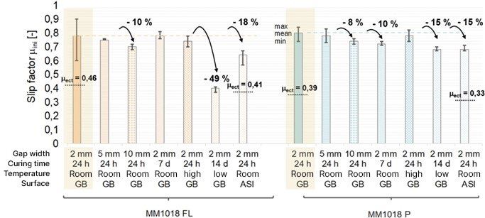
N. Stranghöner, L. Makevičius, A. Korbaj, C. Kunde: The application of duroplastic gap filling material DIAMANT MM1018 in preloaded bolted connections
Source:
Fig. 2 Für die Injektion der Spaltausgleichsmaterialien speziell entwickelte Adapter (hier: beispielhafte Darstellung der Überprüfung der Funktionalität des
Systems an transparenten Acrylglasplatten)
Specially developed adapters for injecting the gap-filling materials (here: exemplary illustration of testing the functionality of the system on transparent
acrylic glass panels)
The already mentioned MM1018 from Diamant Polymer
GmbH in liquid (FL) and pasty (P) form was used as the
gap filling material. The more important technical data for
the gap filling material can be taken from Tab. 2.
3 Use of the gap filling material in slip-
resistant preloaded connections
The results of the slip factor tests taking into account the
use of the gap filling materials MM1018 FL and MM1018 P
are summarised in Tab. 3.
The static tests performed on the reference configuration
of the test specimens with shot-blasted surfaces (GB)
(here: 2 mm gap width, 24 h curing time at room
temperature) (fig. 4: exemplary illustration of a slip-
resistant test specimen, fig. 5: slip displacement / force
Source:
curves) show that the static slip factors µini,mean, calculated
with the respectively measured initial preload, lie for both
Fig. 3 Exemplarische Darstellung des Relaxationsprüfkörpers mit einer materials MM1018 FL and MM1018 P in a comparable
planmäßigen Spaltdicke von 2 mm
Exemplary illustration of the test specimen for relaxation tests with order of magnitude with 0.78 (with a mean slip load of FSm
a planned gap width of 2 mm = 339.2 kN) and 0.80 (FSm = 339.5 kN) respectively.
All tests were carried out at the Institute of Metal and
Lightweight Construction (IML) at the University of
Duisburg-Essen (UDE).
Tab. 2 Wichtigere technische Daten des flüssigen sowie des pastösen Spaltausgleichsmaterials MM1018 FL und MM1018 P nach [20]
Important technical data of the liquid as well as the pasty gap filling materials MM1018 FL and MM1018 P acc. to [20]
Material Field of application Emodulus1) Compressive strength2) Processing time3) [min]
[N/mm2] [N/mm2]
10 °C 20 °C 30 °C
MM1018 FL up to 10 mm 10,000 161 60 30 15
MM1018 P up to 10 mm 10,000 110 30 15 10
1)determined after 7 days of storage at 21 °C and a relative humidity of 60 % | 2) determined on thin plates measuring 100 mm × 100 mm ×
10 mm after 7 days of storage at 21 °C and a relative humidity of 60 % | 3) guiding values for the period during which the material is to be
processed after mixing.
4 Stahlbau 92 (2023), booklet 1 (reprint)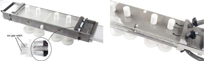
N. Stranghöner, L. Makevičius, A. Korbaj, C. Kunde: The application of duroplastic gap filling material DIAMANT MM1018 in preloaded bolted connections

                                                                                                                                                                                       ARTICLE
Tab. 3 Ergebnisse der GV-Versuche für MM1018 FL und MM1018 P
       Results of slip factor tests for MM1018 FL and MM1018 P

                                                                                Results3)

                                       Temperature1
                                                                                st                                                                 ct          ect
                        Curing time
            Gap width

                                                                                                                                                               X%       µect

                                                      condition

                                                                   st/ct/ect
Material

                                                                                FSm         µini,mean     VX       µnom,mean        µact,mean    90 %

                                                      Surface

                                                                   Tests2)
                                                                                                                                                 FSm
                                                                                [kN]        [–]           [%]      [–]              [–]                        FSm      [–]

            2 mm        24 h           Room           GB            4/1/4       339.2                     9.1       0.77            0.89           n. p.       60 %
                                                      0.78                                                                                                     0.46
                                                                                                          6.2                       0.75
                                       Room           GB+ASI        4/1/5       280.0                               0.6                            n. p.       65 %     0.41
                        14 d                                                                                                        0.76
MM1018 FL

                                                      0.64                                                4
                                                                                                                                                   –           –        –
                        24 h           low            GB            2/–/–       170.7                     4.7                       0.88
                                                      0.40                                                          0.3                            –           –        –
                        7d                                                                                9                         0.88

            5 mm        24 h           Room                         1/–/–       339.3       0.75          0.9      0.77             0.86           –           –        –
            10 mm       24 h           Room                         2/–/–       308.8       0.70          2.8      0.70             0.78           –           –        –

            2 mm        24 h           Room           GB            4/1/4       339.5       0.80          4.6       0.77            0.97           n. p.       50 %
                                                                                                                                                               0.39
                                       Room           GB+ASI        4/1/4       292.1       0.68          2.3                       0.8
                                                                                                                    0.6             3              n. p.       50 %
                        14 d           low            GB            2/–/–       301.7       0.68          6                                                    0.33
MM1018 P

                                                                                                                                    0.8
                        24 h           high                         2/–/–       348.1       0.78          1.7                       2              –           –        –
                                                                                                                    0.6
                        7d             Room                         2/–/–       331.9       0.72          9                         0.9            –           –        –
            5 mm        24 h           Room                         1/–/–       330.9       0.78          9.5      0.75             0.93           –           –        –
            10 mm       24 h           Room                         1/–/–       322.6       0.74          4.2      0.73             0.85           –           –        –
1)Room: measured between 20.5 °C and 23.1 °C, low: 5 °C; high: 40 °C | 2) st: static test; ct: creep test; ect: extended creep test |
3)FSm: mean slip load, µini,mean: mean slip factor in relation to the measured preload at the start of the static tests, VX: coefficient of variation,
µnom,mean: mean slip factor in relation to the normative preload level Fp,C = 110 kN (M16), µact,mean: mean slip factor in relation to the measured
preload on reaching the slip load FSm, n. p.: not passed, µect: slip factor after passing the extended creep test in relation to the normative preload
level Fp,C = 110 kN | Selected reference configuration for the parameter investigations within the framework of the project.

The consideration of the actual preloads at the time of                                      The higher creep tendency of the pasty gap filling material
slipping of a slip-resistant connection leads to slip factors                                was confirmed as expected.
µact,mean of 0.89 for MM1018 FL and 0.97 for MM1018 P
(difference of approx. 9 %) and points in accordance with                                    The static tests carried out on the surface treatment
the results from [20] to the higher creep sensitivity of the                                 GB+ASI with the reference configuration of the test
pasty gap filling material. Since the subsequent creep tests                                 specimens (here: 2 mm gap width, 24 h curing time at
with a load level of 90 % FSm for the two test series had to                                 room temperature) lead as expected in comparison with
be evaluated as not passed, extended creep tests were                                        the investigations into purely-blasted test specimens to
performed in order to determine the slip factor µect. After                                  lower static slip loads FSm and therefore to lower slip
three passed tests for each, slip factors µect of 0.46 and                                   factors µini,mean.
0.39 respectively were determined for MM1018 FL (GB)
(load level 60 % FSm) and MM1018 P (GB) (load level 50 %
FSm).
                                                                                                                                                             Source:

Fig. 4 Exemplarische Darstellung eines GV-Prüfkörpers vor und nach der Durchführung des statischen Versuchs (hier: beispielhaft Referenzkonfiguration mit2
       mm Spaltdicke)
       Exemplary illustration of a test specimen before and after performing the static slip test (here: exemplary reference configuration with 2 mm gap width)

                                                                                                                          Stahlbau 92 (2023), booklet 1 (reprint)                  5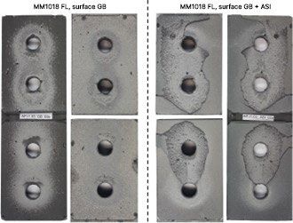
N. Stranghöner, L. Makevičius, A. Korbaj, C. Kunde: The application of duroplastic gap filling material DIAMANT MM1018 in preloaded bolted connections

                                                                                                                   Source:

Fig. 5 Exemplarische Darstellung der Gleitverschiebung-Kraft-Kurven der statischen GV-Versuche für die Prüfkörper mit der ausgewählten
       Referenzkonfiguration (Oberfläche GB, 2 mm Spaltdicke, Raumtemperatur) für Materialien MM1018 FL (a) und MM1018 P (b)
       Exemplary illustration of the slip displacement-load curves of the static slip tests for the test specimens with the selected reference configuration
       (surface GB, 2 mm gap width, room temperature) for materials MM1018 FL (a) and MM1018 P (b)

Poorer adhesion between the coated surface and the gap                                    After three passed tests for each, slip factors µect of 0.41
filling material (fig 6: representative fracture patterns after                           and 0.33 respectively were determined for MM1018 FL
the static slip factor tests performed with the respective                                (GB+ASI) (load level 65 % FSm) and MM1018 P (GB+ASI)
adhesive failure) results in comparison with the                                          (load level 50 % FSm). The higher creep tendency of the
investigations into purely-blasted test specimens in a                                    pasty gap filling material was also confirmed with the
reduction in the slip factor µini,mean of approx. 18 % (here:                             surface treatment GB+ASI.
µini,mean = 0.64 instead of µini,mean = 0.78 for test series GB)
for MM1018 FL and of approx. 15 % (here: µini,mean = 0.68                                 The investigated GB und GB+ASI surface treatments of the
instead of µini,mean = 0.80 for test series GB) for MM1018 P.                             test specimens in combination with the gap filling
Due to the creep tests with a load level of 90 % FSm not                                  materials MM1018 FL and MM1018 P not only point to the
being passed, extended creep tests were performed in                                      expected increased creep sensitivity of the synthetic-based
order to determine the final slip factors.                                                materials, but also highlight the dependence of the slip
                                                                                          factors to be assumed on the adhesive capacity between
                                                                                          the surface and the gap filling material.

6        Stahlbau 92 (2023), booklet 1 (reprint)
N. Stranghöner, L. Makevičius, A. Korbaj, C. Kunde: The application of duroplastic gap filling material DIAMANT MM1018 in preloaded bolted connections
ARTICLE
The static tests carried out on both the liquid and pasty
material MM1018 point to an already sufficiently high
strength of the material after 24 h and therefore
correspond well to the findings from [20]. The reduction in
the static slip factors µini,mean of approx. 10 % after a curing
time of 7 d determined at this point (here: µini,mean = 0.72 in
comparison with µini,mean = 0.80 after a curing time of 24 h)
in the case of the material MM1018 P is more likely
attributable to the small scope of the random tests, but still
confirms the sufficient curing of the material after 24 h.
On the basis of the processing instructions in Z.-3.82-2042
[20], the use of the gap filling materials MM1018 FL and
MM1018 P was also checked at low (here: 5 °C) and high
(here: 40 °C) component and ambient temperatures. It
Source:
should be noted at this point that the material was stored
Fig. 6 Exemplarische Darstellung der Prüfkörper nach den durchgeführten throughout at room temperature. It was shown that the
statischen GV-Versuchen für Prüfkörper mit den Oberflächen GB high assembly temperatures after a curing time of 24 h do
und GB+ASI (hier: Material MM1018 FL)
not lead to a significant reduction in the static slip factors
Exemplary illustration of the test specimens after static slip tests for
the investigated surfaces GB and GB+ASI (here: gap filling material µini,mean either for MM1018 FL or for MM1018 P and
MM1018 FL) therefore correspond to the findings regarding the
compressive strengths at different temperatures and with
Based on the surface treatment/gap filling material different curing times in [20]. Conversely, the application
combination tested, it appears to be conceivable to classify of both the liquid and the pasty gap filling material to
MM1018 FL as friction surface class B according to components with low surface and ambient temperatures
EN 1090-2 (µect > 0.40) and MM1018 P as friction surface (here: 5 °C) is not advisable. Despite the targeted extended
class C according to EN 1090-2 (µect > 0.30). This should storage time (or curing time respectively) of the test
be checked or confirmed by means of supplementary specimens from 24 h to 14 d, the gap filling material could
examinations, including of other surface treatments. In not fully cure or attain its optimal strength properties,
addition to the determination of the slip factor after leading to a reduction in the determined static slip factors
extended creep tests µect on the defined reference µini,mean for MM1018 FL and MM1018 P of approx. 15 % and
configurations and surface treatments, a random approx. 49 % respectively in comparison with the reference
examination of the influence of various possible tests. Such a result does not in any way contradict the
parameters on the load-bearing behaviour of a purely shot- processing instructions in the general building authority
blasted slip-resistant connection was also carried out in approval Z.-3.82-2042. Based on the compressive strength
one to two static tests within the framework of the ZIM development in Z.-3.82-2042, it can be seen that low
cooperation project. In addition to the summary in Tab. 3, temperatures lead to a delayed development of the
the test results for both gap filling materials MM1018 FL strength properties of the material. For practical use on
and MM1018 P are shown graphically in fig. 7. building sites at low temperatures, including a limited
period of time until the bolt sets are preloaded for the first
An increase in the gap width from von 2 mm (reference) to time, this means that the supply of heat for the purpose of
5 mm or 10 mm (maximum recommend gap for the use of material curing, e.g. by infrared heaters or enclosure with
MM1018) shows that the static slip factors µini,mean may air heat radiators, cannot be dispensed with.
already be reduced by up to 10 % both when using 4 Preload behaviour of the bolted
MM1018 FL and when using MM1018 P, wherein the true connections with gap filling
creep behaviour of the gap filling material can only be material
conditionally determined in a static test due to the short
test duration. In order to be able to determine the actual In accordance with the procedure for the slip factor tests
influence of an increase in the gap width on the behaviour and for guaranteeing the reusability of the bolts with strain
of a slip-resistant connection, further extended creep tests gauges, the latter were specifically preloaded to the
need to be carried out in future. nominal preload level Fp,C for HV sets M16 of 110 kN
according to EN 1090-2 or the DASt guideline 024
In addition to the reference curing time of 24 h, the respectively.
possible influence of a curing time of 7 d on the load-
bearing behaviour of a slip-resistant connection was
investigated.
Stahlbau 92 (2023), booklet 1 (reprint) 7N. Stranghöner, L. Makevičius, A. Korbaj, C. Kunde: The application of duroplastic gap filling material DIAMANT MM1018 in preloaded bolted connections
Source:
Fig. 7 Ermittelte Haftreibungszahlen µini,mean (statischer Versuch) und µect (erw. Kriechversuch) für verschiedene Parameter (hier: Spaltdicke, Aushärtezeit,
Montagetemperatur sowie Oberflächenbehandlung) für die Materialien MM1018 FL und MM1018 P
Determined slip factors µini,mean (static test) and µect (extended creep test) for different parameters (here: gap width, curing time, assemblytemperature
and surface treatment) for the materials MM1018 FL and MM1018 P
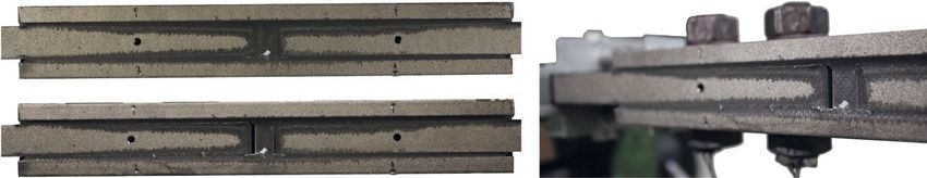
As explained in [28], the drop in the preload occurring In relation to an initial preload Fp,C of approx. 110 kN, the
immediately after tightening can mainly be attributed to mean preload losses ∆Fp,setting,50a,mean in the case of
the so-called overshoot effect of the elastic recovery. In connections with MM1018 FL were approx. 22 % after the
order to determine the real preload losses without the first tightening and only just under 9 % after preloading
elastic recovery portion, the initial preloads Fp,ini were again to Fp,C. In the case of the preloaded connections with
related to a value at 3 s after reaching the peak value. MM1018 P, the preload losses ∆Fp,setting,50a,mean were around
According to the example of the modified torque 33 % after the first tightening and approx. 13 % after re-
preloading method, the 8-bolt connections were tightening. Based on the experimental tests results, it is
specifically re-tightened to the initial preload of Fp,C after a above all the favourable influence of re-tightening (as is
test duration of approx. one month in the case of made possible by modified torque preloading) that should
connections with MM1018 FL or one week in the case of be emphasised. According to the authors' experience in the
connections with MM1018 P. It should be explicitly context of the already completed [29, 30] and currently
pointed out that this was only possible because the ongoing research project, a subsequent compensation of
preloads were subjected to continuous monitoring, for the preload can lead to a reduction in the total preload loss
which reason the bolted connections could also be after the initial preloading of up to 50 % and should be
specifically re-tightened. In practice this is usually not aimed for in particular when using creep sensitive
readily possible with the combined preloading method and materials or multi-layer coating systems.
possibly also unnecessary, because system reserves of the
preloads of more than 30 % are achieved in principle with 5 Summary and outlook
combined preloading. Conversely, in the case of
preloading by means of modified torque preloading, re- Due to manufacturing and assembly-related imperfections
tightening of the preloaded connections after a few days is of steel components, which cannot be avoided despite
by all means common practice and is also urgently sufficient technical competence and equipment, gaps can
recommended by the authors. The complete test duration form during the execution of bolted connections, which,
for the two test series was around two months, during for example, endanger the controlled application of the
which time the preload losses were continuously measured required preload level and can therefore considerably
and subsequently logarithmically extrapolated to the impair the load-bearing capacity and durability of the
possible duration of use of the connection of 50 years. The preloaded bolted connection. As an alternative to the use
test results for the two materials MM1018 FL and MM1018 of stiffeners or in applications where a gap cannot be
P are summarised in Tab. 4. The corresponding log completely compensated by stiffeners, gap filling material
time/preload loss curves for the relaxation tests performed can also be used if an appropriate approval exists.
are shown in fig. 8.
8 Stahlbau 92 (2023), booklet 1 (reprint)N. Stranghöner, L. Makevičius, A. Korbaj, C. Kunde: The application of duroplastic gap filling material DIAMANT MM1018 in preloaded bolted connections
ARTICLE
Source:
Fig. 8 Log Zeit-Vorspannkraftverluste-Kurven der durchgeführten Relaxationsversuche an Verbindungen mit Spaltausgleichsmaterialien MM1018 FL (a) und
MM1018 P (b)
Log time-loss of preload curves of the relaxation tests carried out on test specimens with gap filling materials MM1018 FL (a) and MM1018 P (b)
These experimental investigations are concerned with the The gap filling materials MM1018 FL and MM1018 P
use of the metal polymer MM1018 (in liquid and pasty applied to purely shot-blasted surfaces (GB) and to shot-
form) from Diamant Polymer GmbH in preloaded bolted blasted and ASI-coated surfaces (GB+ASI) (here: valid for
connections. reference configurations consisting of 2 mm gap width and
24 h curing time at room temperature) exhibit in each case
The slip factor tests on the basis of EN 1090-2, Annex G slip factors µect of > 0.40 and > 0.30 respectively after
performed here show a pleasing potential with regard to extended creep tests. A random examination of the
the possible use of the metal polymers MM1018 FL (liquid influence of various parameters on the load-bearing
form) and MM1018 P (pasty form) in slip-resistant behaviour of a purely shot-blasted slip-resistant
preloaded connections. connection shows that an increase in the gap width from
2 mm (reference) to 5 mm or 10 mm can already lead to a
reduction in the load-bearing behaviour on the basis of the
static slip factors µini,mean of up to 10 % in the static test.
Stahlbau 92 (2023), booklet 1 (reprint) 9N. Stranghöner, L. Makevičius, A. Korbaj, C. Kunde: The application of duroplastic gap filling material DIAMANT MM1018 in preloaded bolted connections
Tab. 4 Experimentell ermittelte Vorspannkraftverluste ∆Fp,setting,50a,mean für MM1018 FL und MM1018 P
Experimentally determined preload losses ∆Fp,setting,50a,mean for MM1018 FL and MM1018 P
Initial preloads Preload losses
Temperature1
F 2) Vx3) ∆F 4) Vx
Curing time
Gap width
p,ini,mean p,setting,50a,mean
condition
Material
[kN] [%] [%] [%]
Surface
Phase
MM1018 FL 2 mm 24 h Room GB Tightening 111.0 1.8 22.3 3.0
Re-tightening 111.1 0.7 8.7 9.3
MM1018 P 2 mm 24 h Room GB Tightening 110.7 1.4 33.0 9.1
Re-tightening 111.1 1.0 12.6 14.2
1)Room temperature: measured between 20.5 °C and 23.1 °C | 2) Fp,ini,mean: mean initial preload in relation to approx. 3 s after the peak | 3) VX:
coefficient of variation | 4) ∆Fp,setting,50a,mean: mean preload losses logarithmically extrapolated to 50 years
A further investigation shows that a sufficiently high With the experimental investigations carried out, a
strength of the material is already achieved after 24 hours. fundamental basis was created for the future conception of
With regard to the assembly temperatures, the lower the slip-resistant preloaded connection using the gap filling
temperature range for processing (here: 5 °C according to materials MM1018 FL and MM1018 P in terms of
[20]) is especially to be avoided, as this leads to dimensioning and execution. A broader database, in
incomplete curing even after about two weeks and particular taking into account other surface finishes typical
consequently to a significant reduction in the static slip of steel construction as well as test specimen configurations,
factor µini,mean . the use of super-elastic preloading methods or fatigue
stresses, would be desirable and useful. In the further course
An experimental determination of the pure preload losses of the project, a numerical parameter study based on the
∆Fp,setting,50a,mean at room temperatures shows that, with experimental investigations is planned, which should lead to
regard to a possible service life of 50 years, preload losses the identification of decisive influencing parameters. The
in an order of magnitude of approx. 22 % and 33 % parameter study is intended to expand the existing test
respectively are to be expected for the gap filling materials database (here: further gap widths, faults and defects) and to
MM1018 FL and MM1018 P. At this point, the favourable clarify the borderline cases of applicability, especially with
influence of the re-tightening of a preloaded connection regard to possible recommendations for action. In addition,
should be emphasised. The tests carried out show that re- new formulations for the gap filling materials are to be
tightening can lead to a reduction in the total preload loss developed and investigated.
after the initial preloading of 50 % and even more. While
re-tightening is common practice with modified torque Thanks
preloading, re-tightening is usually not possible and also
The results presented were obtained within the framework
not necessary with combined preloading, as very high
of the ZIM cooperation project "Bri-San-T – DuroFüllSta/
system reserves of more than 30 % are usually achieved
Development of a material model and dimensioning
with combined preloading anyway. Whether and to what
concept for gap filling materials". This project is funded by
extent the preload losses as a result of the use of MM1018
the Federal Ministry for Economic Affairs and Climate
can thus be compensated, must (still) be determined in the
Action on the basis of a resolution of the German
individual case.
Bundestag.
Literature
[1] DIN EN 1090-2:2018-09 (2018) Ausführung von [3] Cheng, L.; Wang, Q.; Ke, Y. (2019) Experimental and
Stahltragwerken und Aluminiumtragwerken – Teil 2: numerical analyses of the shimming effect on bolted joints
Technische Regeln für die Ausführung von with nonuniform gaps. Journal of Mechanical Engineering
Stahltragwerken; Deutsche Fassung EN 1090-2:2018. Science 233, No. 11, pp. 3964–3975.
Berlin: Beuth. Ausgabe Sept.2018. [4] Yun, Y.; An, L.; Gao, G.; Yue, Y. (2017) Effect of Liquid
[2] Comer, A. J.; Stanley, W. S.; Young, T. N.; Ballocchi, P.; Shim on the Stiffness and Strength of the Composite-
George, A. (2011) Thermo-mechanical fatigue analysis of composite Single Lap Joint. DEStech Transactions on
liquid shim in mechanically fastened hybrid joints for Material Science and Engineering.
aerospace applications. Proceedings of the 16th
International Conference on Composite Structures (ICCS
16), Porto, June 28–30, 2011.
10 Stahlbau 92 (2023), booklet 1 (reprint)N. Stranghöner, L. Makevičius, A. Korbaj, C. Kunde: The application of duroplastic gap filling material DIAMANT MM1018 in preloaded bolted connections
ARTICLE
[5] Yue, X.; An, L.; Ye, X.; Wang, C.; Cai, Y.; Xiao, R. (2020) [19] Boretzki, J.; Albiez, M. (2022) Static strength and load bearing
Effect of Gap and Shims on the Strain and Stress State of the behaviour of hybrid bonded bolted joints: experimental and
Composite-Aluminum Hybrid Bolted Structure. International numerical investigations. The journal of Adhesion, pp. 1–26.
Journal of Aerospace Engineering, No. 5, pp. 1–19. https://doi.org/10.1080/00218464.2022.2033619
[6] Han, N.; Jiang, Q. (2016) Investigation into Bearing [20] abZ Z-3.82-2042 (2018) Metall Polymer „MM1018P“ und
Capacity of Composite Bolted Joints with Different Shim. „MM1018FL“. Berlin: Deutsches Institut für Bautechnik.
Proceedings of the 4th International Conference on Zulassungsbescheid vom 15. Jan. 2018.
Sensors, Mechatronics and Automation (ICSMA 2016), [21] DIN EN ISO 8501-1:2007-12 (2007) Vorbereitung von
Zhuhai, Nov. 12–13, 2016. Stahloberflächen vor dem Auftragen von
[7] Liu, l. (2014) The influence of the substrate’s stiffness on the Beschichtungsstoffen – visuelle Beurteilung der
liquid shim effect in composite-to-titanium hybrid bolted Oberflächenreinheit – Teil 1: Rostgrade und
joints. Journal of Aerospace Engineering 228, No. 3, pp. Oberflächenvorbereitungsgrade von unbeschichteten
470–479. Stahloberflächen und Stahloberflächen nach ganzflächigem
[8] Attahu, C.; Luling, A.; Zhaoqing, L.; Guoqiang, G. (2018) Entfernen orhandener Beschichtungen, Deutsche Fassung
Influence of Shim Layers on Progressive Failure of a EN ISO 8501-1:2007. Berlin: Beuth.Ausgabe Dez. 2007.
Composite Component in Composite-Aluminium Bolted [22] DIN EN ISO 8503-1:2013-05 (2013) Vorbereitung von
Joint in Aerospace Structural Assembly. Transactions of Stahloberflächen vor dem Auftragen von
Nanjing University of Aeronautics and Astronautics 35, Beschichtungsstoffen – Rauheitskenngrößen von
No. 1, pp. 188–202. gestrahlten Stahloberflächen – Teil 1: Anforderungen und
[9] Chang, J.; Yang, Y.; Liu, X.; Gao, H.; Wang, Y. (2019) A Begriffe für ISO-Rauheits vergleichsmuster zur Beurteilung
mixed shimming method in eliminating the gaps during the gestrahlter Oberflächen, Deutsche Fassung EN ISO
assembly process of the complex structures. IOP Conference 8503-1:2012. Berlin: Beuth. Ausgabe Mai 2013.
Series: Materials Science and Engineering 493. [23] Makevičius, L.; Stranghöner, N.; Kunde, C.; Thelen, S.
[10] Dhôte, J. X.; Comer, A. J.; Stanley, W. F.; Young, T. M. (2021) Duroplastic gap filling materials in preloaded bolted
(2014) Investigation into compressive properties of liquid connections. Proceedings of Eurosteel 2021 Conference,
shim for aerospace bolted joints. Composite Structures 109, Sheffield, Sep. 1–3, 2021. ce/papers 4, No. 2–4, pp. 197–
No. 1, pp. 224–230. 202.
[11] Attahu, C.; Luling, A. (2017) Influence of assembly gap and [24] Kunde, C.; Di Gegorio, L. (2019) Time-optimized assembly
shims on the strain and stress of bolted composite- of bridge bearings: Force-fit gap compensation of steel-
aluminum structures. ARPN Journal of Engineering and connections with metal-polymers. Proceedings of Nordic
Applied Sciences 12, No. 5, pp. 1593–1619. Steel 2019, Copenhagen, Sep. 18–20, 2019. ce/papers 3, No.
[12] Wang, Q.; Dou, Y.; Cheng, L.; Ke, Y. (2017) Shimming 3–4, pp. 421–425.
design and optimal selection for non-uniform gaps in wing [25] DIN EN 14399-4:2015-04 (2015) Hochfeste vorspannbare
assembly. Assembly Automation 37, No. 4, pp. 471–482. Garnituren für Schraubverbindungen im Metallbau – Teil
[13] Dörnen, A.; Trittler, G. (1956) Neue Wege der 4: System HV-Garnituren aus Sechskantschrauben und -
Verbindungstechnik im Stahlbau. Der Stahlbau 25, H. 8, S. muttern; Deutsche Fassung EN 14399-4:2015. Berlin:
181–184. Beuth. Ausgabe Apr. 2015.
[14] Trittler, G.; Dörnen, A. (1964) Die vorgespannte [26] DIN EN 14399-6:2015-04 (2015) Hochfeste vorspannbare
Klebverbindung (VK-Verbindung), eine Weiterentwicklung Garnituren für Schraubverbindungen im Metallbau – Teil 6:
der Verbindungstechnik im Stahlbau. Der Stahlbau 33, H. Flache Scheiben mit Fase; Deutsche Fassung EN 14399-
9, S. 257–269. 6:2015. Berlin: Beuth. Ausgabe Apr. 2015.
[15] Wanner, M.-C.; Henkel, K.-M.; Blunk, C.; Glienke, R. [27] DASt-Richtlinie 024:2018-06 (2018) Anziehen von
(2011) Entwicklung von Hybridfüge verbindungen in geschraubten Verbindungen der Abmessungen M12 bis M36.
Metallwerkstoffen im Hinblick auf die Tragfähigkeit und Düsseldorf: Stahlbau Verlags- und Service GmbH.
Dichtigkeit. EFB-Kolloquium Blechverarbeitung 2011 – [28] Afzali, N.; Pilhagen, J.; Manninen, T.; Schedin, E.;
Hochfeste und hybride Materialien – Schnelle Umform- und Stranghöner, N. (2017) Preload losses in stainless steel
Fügeverfahren, Tagungsband T-032. Bad Boll, 29./30. bolting assemblies. Steel Construction 10, No. 4, pp. 310–318.
März 2011. https:// doi.org/10.1002/stco.201710041
[16] Glienke, R.; Ebert, A.; Denkert, C.; Henkel, K.-M.; Kalich, [29] Stranghöner, N.; Makevičius, L.; Henkel, K.-M.; Glienke, R.;
J.; Füssel, U. (2017) Erhöhung der Tragfähigkeit von GV- Dörre, M. (2019) Entwicklung eines Konzeptes zur
Verbindungen durch den Einsatz von Klebstoff. Stahlbau 86, H. Erfassung von Vorspannkraft verlusten in vorgespannten
9, S. 811–830. https://doi.org/10.1002/stab. 201710493 Schraubverbindungen unter Ermüdungsbeanspruchung.
[17] Afzali, N. (2021) Slip-Resistant Connections made of Carbon Schlussbericht P 1091. Düsseldorf: Forschungsvereinigung
and Stainless Steel [Dissertation]. Schriftenreihe Institut Stahlanwendung e. V., FOSTA.
für Metall- und Leichtbau, Universität Duisburg-Essen, Band [30] Stranghöner, N.; Makevičius, L.; Henkel, K.-M.; Glienke, R.;
8. Aachen: Shaker Verlag. Dörre, M. (2019) Vorspannkraftverluste geschraubter
[18] Gerke, T.; Denkert, C.; Dörre, M.; Glienke, R.; Flügge, W.; Verbindungen infolge beschichteter Kontaktflächen. Stahlbau
Vallée, T.; Fricke, H.; Mayer, B. (2021) Weiterentwicklung 87, H. 10, S. 991–1009. https://doi.org/10.1002/
der vorgespannten Hybridverbindung mit Schließringbolzen und stab.201810014
hochfesten Schrauben. EFB-Forschungsbericht Nr. 558.
Stahlbau 92 (2023), booklet 1 (reprint) 11N. Stranghöner, L. Makevičius, A. Korbaj, C. Kunde: The application of duroplastic gap filling material DIAMANT MM1018 in preloaded bolted connections
Authors
Univ.-Prof. Dr.-Ing. habil. Natalie Dipl.-Ing. (FH) Carsten Kunde
Stranghöner carsten.kunde@diamant-polymer.de
natalie.stranghoener@uni-due.de Diamant Polymer GmbH
University of Duisburg-Essen Marie-Bernays-Ring 3a
Institute of Metal and Lightweight 41199 Mönchengladbach
Construction
Universitätsstrasse 15
45141 Essen
Lukas Makevičius M.Sc. (Corresponding
author)
lukas.makevicius@uni-due.de
University of Duisburg-Essen Quote this article
Institute of Metal and Lightweight Stranghöner, N.; Makevičius, L.; Korbaj, A.; Kunde, C. (2023) The
Construction application of duroplastic gap filling material DIAMANT MM1018 in preloaded
Universitätsstrasse 15
bolted connections. Stahlbau 92, Booklet 1, p. 27–38.
45141 Essen
https://doi.org/10.1002/stab.202200069
Anas Korbaj B.Sc. This article was assessed in a peer review process. Submitted: 10 October
anas.korbaj@uni-due.de 2022; accepted: 23 November 2022.
University of Duisburg-Essen
Institute of Metal and Lightweight
Construction
Universitätsstrasse 15
45141 Essen
12 Stahlbau 92 (2023), booklet 1 (reprint)You can also read