The ARMM System - Autonomous Steering of Magnetically-Actuated Catheters: Towards Endovascular Applications - Surgical Robotics Lab
←
→
Page content transcription
If your browser does not render page correctly, please read the page content below
IEEE ROBOTICS AND AUTOMATION LETTERS, VOL. 5, NO. 2, APRIL 2020                                                                                                       705

            The ARMM System - Autonomous Steering
            of Magnetically-Actuated Catheters: Towards
                    Endovascular Applications
    Christoff M. Heunis , Yannik P. Wotte, Jakub Sikorski , Guilherme Phillips Furtado , and Sarthak Misra

   Abstract—Positioning conventional endovascular catheters is
not without risk, and there is a multitude of complications that
are associated with their use in manual surgical interventions. By
utilizing surgical manipulators, the efficacy of remote-controlled
catheters can be investigated in vivo. However, technical challenges,
such as the duration of catheterizations, accurate positioning at
target sites, and consistent imaging of these catheters using non-
hazardous modalities, still exist. In this paper, we propose the
integration of multiple sub-systems in order to extend the clinical
feasibility of an autonomous surgical system designed to address
these challenges. The system handles the full synchronization of
co-operating manipulators that both actuate a clinical tool. The
experiments within this study are conducted within a clinically-
relevant workspace and inside a gelatinous phantom that rep-
resents a life-size human torso. A catheter is positioned using
magnetic actuation and proportional-integral (PI) control in con-
junction with real-time ultrasound images. Our results indicate an
average error between the tracked catheter tip and target positions
                                                                                     Fig. 1. The Advanced Robotics for Magnetic Manipulation (ARMM) system
of 2.09 ± 0.49 mm. The median procedure time to reach targets                        in a clinical setting. The system is envisioned to employ magnetic actuation to
is 32.6 s. We expect that our system will provide a step towards                     assist clinicians during endovascular interventions. Two manipulators respec-
collaborative manipulators employing mobile electromagnets, and                      tively actuate an electromagnetic coil ! A , and an ultrasound transducer !    B . An
possibly improve autonomous catheterization procedures within                        automated catheter insertion device ! C , inserts catheters into an arterial phantom
endovascular surgeries.                                                              model ! D , fabricated from computed tomography (CT) images. The poses of all
                                                                                     objects are tracked in real-time using a motion capture system !     E.
   Index Terms—Medical robots and systems, surgical robotics:
steerable catheters/needles, surgical robotics: planning.
                                                                                     intervention would involve the insertion of a catheter in the groin
                             I. INTRODUCTION
                                                                                     to access the heart or important arterial branches [3]. The catheter

S    TEERING and positioning a catheter in target vessels dur-
     ing endovascular surgery is a challenging task [1]. In partic-
ular cases, standard interventions for endovascular repair involve
                                                                                     is, in most cases, tracked by utilizing X-ray imaging facilitated
                                                                                     by the injection of contrast material, which discriminates the
                                                                                     catheter from the arterial tree [4]. Despite its convenience, X-ray
high-risk complications, which can lead to unnecessary trauma                        imaging causes additional safety risks due to the prolonged
during insertion [2]. Moreover, the accuracy of steering is highly                   exposure of both patients and clinicians to ionizing radiation.
dependent on the abilities of a clinician. A typical endovascular                       This brings to light two main complications in the clinical
                                                                                     room, which are the limited diversity of actuation methods of
   Manuscript received September 10, 2019; accepted December 24, 2019.               surgical instruments, and the real-time visualization of such
Date of publication January 9, 2020; date of current version January 21, 2020.       instruments in a hazard-free environment. Actuating surgical
This letter was recommended for publication by Associate Editor Z. Li and
Editor P. Valdastri upon evaluation of the reviewers’ comments. This work was        instruments by robotic and computer-aided means have expe-
supported by funds from the Netherlands Organization for Scientific Research         rienced two major evolutions in the past decade. First, novel
(Innovational Research Incentives Scheme – VIDI: SAMURAI project # 14855).           actuation methods, including the use of magnets for surgical
(Corresponding author: Christoff Marthinus Heunis.)
   C. M. Heunis, Y. P. Wotte, J. Sikorski, and G. P. Furtado are with the Surgical   instrument actuation, have advanced the endovascular industry
Robotics Laboratory, Department of Biomechanical Engineering, University of          in critical ways [5]–[8]. Next, when compared to human-in-
Twente 7500 AE, Enschede, The Netherlands (e-mail: c.m.heunis@utwente.nl;            the-loop actuation of surgical instruments, multiple serial-link
y.p.wotte@utwente.nl; j.sikorski@utwente.nl; g.phillipsfurtado@utwente.nl).
   S. Misra is with the Surgical Robotics Laboratory, Department of Biomedical       robotic actuators (manipulators) have shown to offer decreased
Engineering, University of Groningen and University Medical Centre Groningen         labor costs, a greater range of motion of instruments, and im-
9713, GZ, Groningen, The Netherlands (e-mail: s.misra@utwente.nl).                   proved ergonomics for the clinician [9]–[12]. To support this
   This letter has supplementary downloadable material available at http://
ieeexplore.ieee.org, provided by the authors.                                        notion, we have developed a novel and highly versatile system
   Digital Object Identifier 10.1109/LRA.2020.2965077                                for the magnetic actuation of surgical instruments (Fig. 1).
                          2377-3766 © 2020 IEEE. Personal use is permitted, but republication/redistribution requires IEEE permission.
                              See https://www.ieee.org/publications_standards/publications/rights/index.html for more information.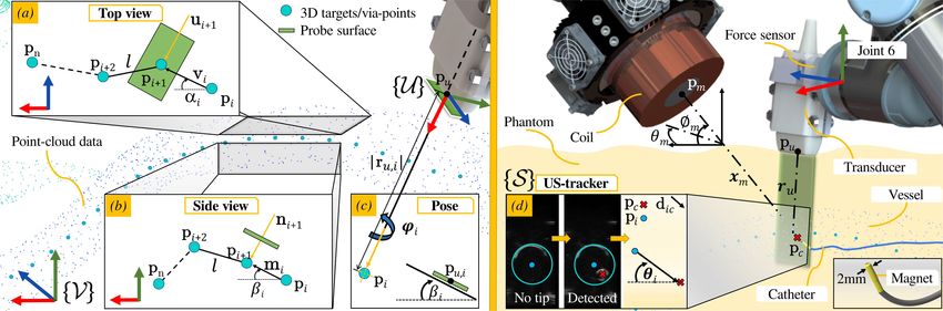
706                                                                        IEEE ROBOTICS AND AUTOMATION LETTERS, VOL. 5, NO. 2, APRIL 2020

The Advanced Robotics for Magnetic Manipulation (ARMM)                  II. ADVANCED ROBOTICS FOR MAGNETIC MANIPULATION
system employs, amongst others a single, cored electromagnetic
                                                                         This section describes the apparatus used in the ARMM
coil attached to a 6 degree-of-freedom (DoF) manipulator arm,         system. The implemented methods result from two phases:
which can be used to generate codirectional, prescribed magnetic
                                                                      pre-operative planning of a patient-specific arterial model, and
fields and forces with independently controlled magnitudes [13].
                                                                      intra-operative surgery involving catheterization.
Similar studies have been conducted on the remote steering of
magnetic catheters. Charreyron et al. demonstrated a proof-of-        A. The ARMM Manipulators
concept for delivering drugs to precise locations inside the retina
using a magnetic microcatheter [14]. The positioning accuracy            The ARMM system consists of two serial-link manipulators
of their system was limited by the workspace illumination con-        (Models UR5 and UR10, Universal Robots, Odense, Denmark).
ditions. Jeong et al. proposed a magnetically steerable guidewire     These manipulators employ a native interface of both manip-
using Helmholtz coils [15]. The guidewire was steered inside a        ulators to communicate with their own embedded controllers.
phantom with five different arterial branches. Finally, a similar     These controllers execute the movement of the manipulators
mobile electromagnetic coil system has been introduced that           upon receiving a pose command, expressed as a set of joint
enables motion control of a magnetic catheter inside three-           velocities. A linear US L14-5 transducer (SonixTouch Q+, BK
dimensional (3D) printed channels [16].                               Medical, Quickborn, Germany) is mounted to the UR5 (here-
   While the aforementioned studies have indicated a con-             inafter referred to as ‘RobUltra’). The UR10 (referred to as
siderable amount of success in steering magnetic catheters,           ‘RobARMM’) carries an electromagnet capable of generating
these tests were either executed within non-anthropomorphic           prescribed magnetic fields and gradients at the point of interest.
mock-ups [16], or using computationally expensive mechanical          The effective workspace of the ARMM system can be approxi-
models for catheters [15]. Furthermore, while accurate position-      mated by a sphere with a radius of 783 mm, though positioning
ing of catheters has been reported to be between 1.9 ± 0.40 mm        the coil at a safe distance of 50 mm using RobARMM could
and 4.18 ± 1.76 mm under electromagnetic guidance, these              allow for a maximum spherical workspace radius of 1300 mm.
studies have presented simplified scenarios in highly-controlled      As the coil should be positioned outside the human body, we
environments and small (< 20 × 30 × 50 cm3 ) workspaces that          assume that the catheter is located between 50 mm and 200 mm
deviate from clinically-relevant sizes [5], [17]. Finally, sim-       away from the coil at any instance during the intervention. The
ilar actuation systems have been designed to steer catheters          coil can generate fields of at least 20 mT and gradients of more
at system bandwidths of 10–20 Hz [8]. This especially influ-          than 0.6 mT/mm, similar to the ones used in previous studies on
ences the duration of catheterization procedures, as indicated        magnetic catheters as discussed in our previous work [13].
by Manstad et al., who reported median durations of between           B. Magnetic Actuation of Flexible Catheters
34.5–41.5 s for steering catheters to in vivo target sites [18].
To the best of our knowledge, no report has been found so far            Magnetic interaction occurs between two principal agents: the
that demonstrates the integration of multiple surgical systems        dipole (m ∈ R3 ) attached to the actuated device and the field
that operate autonomously at a higher bandwidth to achieve            (B(p) ∈ R3 ) at a point (p ∈ R3 ) [19]. The magnetic catheter
similar accuracies or durations. In this paper, we demonstrate        implemented within the ARMM system is actuated by varying
that magnetic catheters can be autonomously actuated in a             the current supplied to the external electromagnetic coil. The
clinically-relevant environment. We achieve this within a larger      current supply to the coil is controlled and amplified using
workspace than that of the aforementioned studies, in a volume        a XenusPlus EtherCAT (XEL-230-40, Copley Controls, Can-
of 9 m3 . This environment includes a phantom with pulsating          ton, USA) amplifier. The actuated instrument is a commercial
fluid flow, feedback from US images of the catheter tip, and          coronary guide catheter (Sherpa NX Active, Medtronic, Min-
two collaborative manipulators. We implement a simple, yet            neapolis, United States, diameter: 2 mm, length: 500 mm). The
time-efficient approach that does not require an explicit model of    catheter shaft consists of low-density polyethylene (HDPE) with
the catheter mechanics. The catheter tip is controlled at a stable    a stiffness of ±1.5 N·m/rad and a hydrophilic surface coating to
30 Hz to reach targets provided by an end-user, and a US-based        provide a smooth, low-friction surface. Five cylindrical magnets
template matching algorithm.                                          (NdFeB, diameter: 2 mm, length: 2 mm) are embedded in its tip.
   This paper is organized as follows: Section II describes the          A catheter insertion device (CID) is designed to continuously
serial-link manipulators and apparatus used in the ARMM sys-          feed or retract catheters with sizes ranging from 3–34 Fr into
tem. Our gelatin phantom model, catheter insertion device, and        the port of entry, such as an incision in the groin. The shaft
magnetic endovascular catheter design are explained. This is          of the catheter is gripped between a gear and bearing structure,
followed by the control algorithms for magnetic actuation, as         and fed through a tube by a servo motor (MX-64AR Dynamixel,
well as an outline of the path- and trajectory planning of the        Robotis, South Korea). The insertion is done linearly with speeds
catheter tip and manipulators in Section III. In Section IV,          ranging between 1.3–6.4 mm/s.
we demonstrate the closed-loop control of the catheter in a
clinically-relevant environment, followed by the results and a        C. Arterial Phantom Model Fabrication
discussion of these results. Section V concludes this paper and          An anthropomorphic phantom model of the human abdom-
provides directions for future work.                                  inal arteries is fabricated from raw pre-operative computed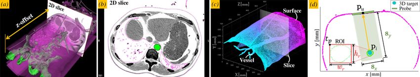
HEUNIS et al.: THE ARMM SYSTEM - AUTONOMOUS STEERING OF MAGNETICALLY-ACTUATED CATHETERS                                                                       707

Fig. 2. The fabrication process of the arterial phantom model. (a) Axial (A), sagittal (S) and coronal (C) views of a segmented scan of a male torso are extracted
directly from computed tomography (CT) slices. Everything other than the vasculature of interest (green) has been masked. (b) The scan is then prepared as a mesh
object in Meshlab (Visual Computing Lab, Pisa, Italy), and registered within the phantom reference frame ({V}), before transformed to the global reference frame
({G}). (c) The point-cloud dataset (C ∈ Rm×3 ), where m is the number of datapoints (40,212). (d) The final stereolithography (SLA) 3D-printed model, before
being submerged in gelatin.

tomography (CT) data (Fig. 2(a-d)). CT slices of a 62-year old                    3D offset with respect to the phantom reference frame. We
anonymous male torso (Medisch Spectrum Twente, Enschede,                          employ the aforementioned ICP method for determining the
The Netherlands) are converted to a mesh object (Meshlab,                         reconstruction accuracy of the US images, resulting in an overall
Visual Computing Lab, Pisa, Italy), and imported to computer-                     mean error of 0.85 ± 0.56 mm. Finally, a 3D volume of the
aided design (CAD) software (Solidworks, Dassault Systemes,                       phantom is displayed on an interactive screen that allows the
Tennessee) for editing. For our experiments, the external, inter-                 operator to select any target region, or 3D points of interest,
nal and common iliac arteries through to the descending aorta                     within the phantom, with sub-millimeter precision.
are 3D-printed using stereolithography (SLA) and submerged in
a mix of chemical gelatin and diluted water (80 g/L). Pulsating                                  III. CONTROL OF THE ARMM SYSTEM
fluid flow is simulated through the arteries using a peristaltic
                                                                                     In this section, we present the workflow as it occurs chrono-
pump (ISM 404, Ismatec, Wertheim, Germany). This fluid
                                                                                  logically through the operative phases. We start by explaining
consists of a mixture of water, water-soluble silicone oil, and
                                                                                  the pre-operative US acquisition phase, followed by the path-
glycerin, which has been proven to approximate an appropriate
                                                                                  planning of the catheter tip and the manipulators. Finally, the
sonographic appearance of blood flow in US images [20].
                                                                                  control strategy for the manipulators during the intra-operative
   The reconstruction accuracy of the fabricated model is es-
                                                                                  phase is explained.
timated by registering four known landmarks to a point-cloud
dataset (C ∈ Rm×3 ) of the virtual arteries. These landmarks
                                                                                  A. Ultrasound Reconstruction Using Hybrid Control
are registered in the ARMM workspace using an Optitrack
Flex13 motion capture system (NaturalPoint Inc., Corvallis,                          When the transducer travels along a trajectory on the phantom,
USA). Next, the closest-point distances between the mesh                          we implement hybrid force-position control with a force of 2
vertices and points are measured in a mesh editing software                       N, in order to produce clear US images [24]. In the case that
(CloudCompare V211, EDF R&D, Corsica, France), resulting                          the transducer follows a trajectory in space, position control is
in a mean distance of 0.75 ± 0.08 mm. Finally, the trans-                         used. Let us consider the tool pose of RobUltra, expressed as a
formation matrix between the point-cloud and the fabricated                       position (pu ∈ R3 ) and angle-axis orientation (θu ∈ S3 ). The
model is determined through an iterated closest point (ICP)                       trajectory of the tool of the RobUltra end-effector is provided
algorithm [21]. US image acquisition is implemented during                        by a set of via-points (i : 1 → n). We implement a modulated
both the pre-operative and intra-operative phases to assist with                  proportional-integral (PI) position-force and modulated propor-
US transducer calibration, 3D reconstruction, and catheter tip                    tional (P) orientation controller to realize a trajectory for this
tracking. Cross-section brightness scans (B-scans) are acquired                   point, moved along the gelatine surface. Each point is reached
at a rate of 30 Hz, while 2D images (size 45 × 90 mm) are                         with end-effector velocity (Ve ) provided by
captured at a 10 MHz central frequency with a focus depth of                                   !              "                # $ ∞        %
                                                                                                                             5
20−40 mm and a maximum depth of 90 mm. The US transducer                             Ve = Vd 1 − e−|E|/R Ê + e−|E|/R I                E dt , (1)
is rigidly connected to the RobUltra end-effector, which enables                                                                             0

us to know its exact relative pose within the phantom reference                   where Vd is the maximum tool velocity, E ∈ R3 is the position
frame ({V}), and global coordinate frame ({G}) (Fig. 2(b)).                       error between pu,i and pu,i+1 , and R is a threshold for the
Reconstructing the phantom volume is done after extracting 2D                     stopping region. The term (1 − e−|E|/R ) ensures continuity to
images that geometrically correspond to the printed model on a                    avoid possible control artifacts caused by measurement noise.
precalculated trajectory. A 3-axis force sensor (K3D40, Mesys-                    The end-effector orientation is described by two unit vectors
teme AG, Henningsdorf, Germany) is connected between the                          (q̂6,z ∈ R3 and q̂6,y ∈ R3 ) which denote the z and y-axes of
US transducer holder and the RobUltra end-effector. This allows                   joint 6 of RobUltra. The desired angular velocity (ω e ∈ R3 ) to
us to control the desired contact force between the transducer                    minimize angular errors (θz and θy ) in order to reach the final
surface and the phantom [22]. A series of volume pixels from                      target orientation is given as follows:
binary US images are used as coordinates on a new point-cloud                                   !             "           !           "
dataset [23]. The pose of RobUltra allows us to determine the                         ω e = ωz 1 − e−|θz |/γ ω̂ z + ωy 1 − e−|θy |/γ ω̂ y , (2)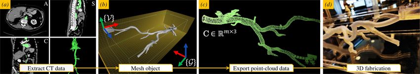
708 IEEE ROBOTICS AND AUTOMATION LETTERS, VOL. 5, NO. 2, APRIL 2020
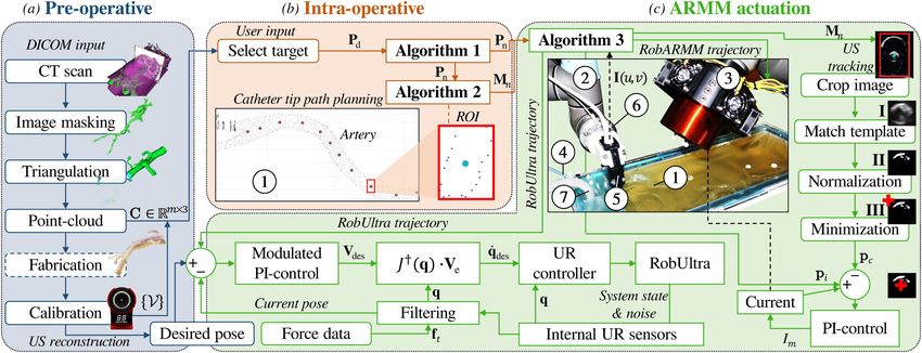
Fig. 3. A path consists of a set of 3D via-points (pn ) for the catheter tip position (pc ). We calculate the desired positions of the coil center point (pm ) and of the
ultrasound (US) transducer point (pu ), as well as their respective distance vectors (xm ) and (ru ) to the catheter tip. (a) The xz-plane of the via-points showing
target points (pi ) for n targets. This allows for calculating the direction vector (vi ) of a via-point (i + 1), and its normal vector (ui+1 ) to derive the angle (αi ).
(b) Similarly, the direction vector (mi ), and its normal vector (ni+1 ) to the closest surface point are calculated to derive the inclination angle (βi ). (c) The angle
(αi ) is used to calculate the rotation angle (ϕi ) of the transducer at a target point (pi ). The offset vector (ru,i ) is calculated by the minimum Euclidean distance
between these points. (d) The 2D catheter tip position is detected using a template-based detection algorithm. RobARMM (Universal Robots, Odense, Denmark) is
positioned using spherical coordinates, where we define θm to be the azimuthal angle in the xz-plane from the x-axis and φm is the polar angle, from the positive
y-axis. 2D US images are used to magnetically deflect the tracked tip (denoted by c) to the target via-point (denoted by i) by minimizing the error of the distance
(dic ) between these two points.
where ωz and ωy are the maximum angular velocities of q̂6,z velocity as an input to the manipulator. Using the task velocity
and q̂6,y . The constant (γ) is analogous to R in (1). Provided in (1), joint velocities (q̇) are computed from the manipulator
the current (θcu ) and desired (θiu ) end-effector orientation, the Jacobian (J ∈ R6×6 ) inverse approach, satisfying
desired angle (θz ) and angular velocity (ω̂ z ) are given by
q̇ = J† Ve (pu ). (9)
θz = arcsin (|q̂c6,z × q̂i6,z |), (3) †
J denotes the damped pseudo-inverse of J, given by [25]:
q̂c6,z × q̂i6,z
ω̂ z = . (4) J† = JT (JJT + ρ2 I)−1 , (10)
sin(θz )
Calculating θy requires a rotation matrix for a rotation by an where ρ is the damping coefficient and I ∈ R6×6 is the iden-
tity matrix. Furthermore, we optimize the control parameters
angle (θ) about the unit vector (k̂), which yields
before executing experiments by simulating a dynamic model
θy = arcsin |(Rk (θz , ω̂ z )q̂c6,y ) × q̂i6,y |, (5) of RobUltra inside a virtual robot experimentation platform
(V-REP) API framework (BlueZero, Blue Workforce, Aalborg,
(Rk (θz , ω̂ z )q̂c6,y ) × q̂i6,y Denmark).
ω̂ y = RTk (θz , ω̂ z ) . (6)
sin(θy )
Finally, PI-force control between the transducer and phan- B. Intra-Operative Control
tom surface is implemented. Direct contact is ensured using a During the intra-operative phase, an end-user is required to se-
setpoint velocity (V(t)) defined by lect the final target point for the catheter tip within the phantom,
V[k] = Kp fe [k] + Ki V[k − 1], (7) the point-cloud of the anatomical part, as well as the distance
(lmax ) between the via-points (Algorithm 1). As such, paths
where the proportional gain (Kp ) and the integral gain (Ki ) for the catheter tip are generated a priori to allow the catheter
are empirically determined to be 0.5 and 0.7 respectively, k to reach its final target position (pd ∈ R3 ) inside the vessel
describes the discrete time index, and fe = (fd − ft ) is the force volume. For our experiments, we implement a path planner that
error between the desired (d) and actual (t) tool forces, measured returns a matrix composed of 3D target points (pn ∈ Rn×3 ).
by the force sensor. For hybrid force-position control, we select This is done for n target points, each at the centroid of the
the velocity component of the end-effector perpendicular to the surrounding artery. The resulting targets can be used as either a
gelatin surface (i.e. aligned with the x-axis of the transducer final target for the catheter tip or via-points (pi ∈ R3 ) between
(Fig. 3), frame {U }) to be controlled by force-control. The the insertion point and end-point, to generate trajectories for the
position error (E) of (2) becomes manipulators.
Following this, we geometrically determine, for each via-
E|| = E − x̂ · (x̂ · E), (8)
point, the US transducer pose, described as an axis-angle rotation
where E|| is the position error component parallel to the sur- vector. We aim to position the transducer such that its center
face and x̂ is the unit vector perpendicular to the surface. point coincides with the shortest distance vector between the
Finally, we traverse the generated trajectories with specified desired via-point of the catheter tip, and the point of contact
joint velocities—that is, we provide the resultant end-effector on the surface. Furthermore, it should be rotated to provide a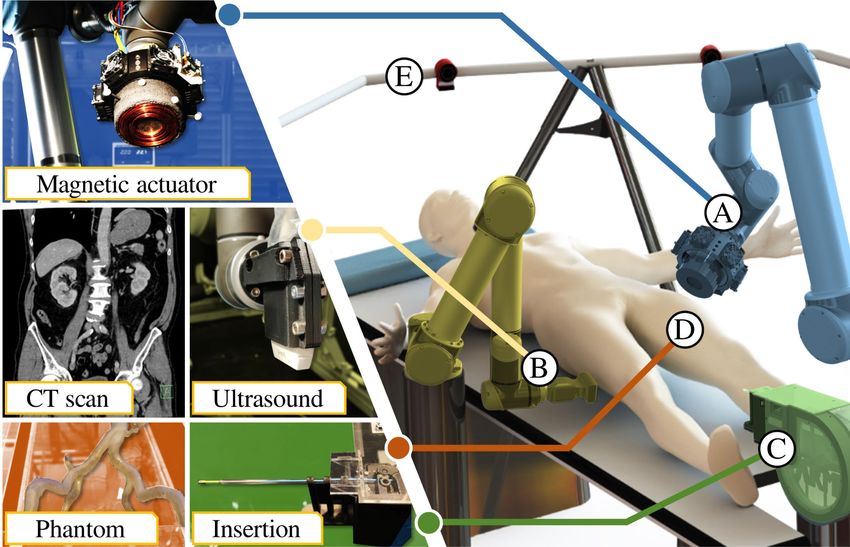
HEUNIS et al.: THE ARMM SYSTEM - AUTONOMOUS STEERING OF MAGNETICALLY-ACTUATED CATHETERS                                                                       709

Fig. 4. Deriving the ultrasound (US) transducer pose from the point-cloud set: (a) Once a 3D target for the catheter tip is known, a 3 mm thick computed
tomography (CT) slice is extracted at the z-offset. (b) The 2D view of the extracted slice, with the artery masked in green, and the surrounding soft tissue in
pink. (c) The anatomical parts of interest are converted to an interactive 3D point-cloud set (d) The corresponding 2D point-cloud representation is a result from
combining xyz-datapoints at each target in a 2D CT slice. This slice is used to determine the transducer center point (pu ) by calculating the minimum distance
(yellow arrow) from the surrounding points (pink) to the catheter tip target position (pi ). The maximum US image width (Sx ) and depth (Sy ) is approximated by
a planar workspace of 90 × 45 mm. Furthermore, the region of interest (ROI) is denoted by a bounding box with upper-left corner xy-position (tp ), width (wr )
and height (hr ).

                                                                                  to get the rotation angle (Fig. 3(c))
                                                                                                                ϕi = π/2 − αi .                             (12)
                                                                                     The transducer inclination angle (βi ) (Fig. 3(b-c)) is calcu-
                                                                                  lated similarly to (12). In our case, the phantom surface is
                                                                                  assumed to be level, such that, for βi = 0, the axis-angle rotation
                                                                                  for the transducer (θu,i ) is calculated as
                                                                                                        θu,i = −vu,i RUV R(βi , ϕi ),                       (13)
                                                                                  where R(βi , ϕi ) ∈ SO(3) is the input 3D rotation matrix and
                                                                                  RUV is the rotation between the phantom and transducer frame.
                                                                                  Furthermore, when the offset vector (ru,i ) is known, we derive
                                                                                  vu,i using [27]:
                                                                                                vu,i = ru,i cos(ϕi ) + (k × ru,i ) sin(ϕi )
                                                                                                          + k(k · ru,i )(1 − cos(ϕi )),                     (14)
                                                                                  where k ∈ R represents the rotation vector (the x-axis of the
                                                                                                   3

                                                                                  transducer).

                                                                                  C. Ultrasound Image Template Matching Algorithm
                                                                                     Once the user defines a catheter target at a known offset on the
                                                                                  phantom surface (Fig. 4(a)), the via-points for both the catheter
                                                                                  and transducer are calculated. To establish proper insertion con-
                                                                                  trol, the catheter tip has to be tracked in the US images. Hence,
                                                                                  we implement an OpenCV (version 3.4.8) image processing
                                                                                  library to detect and track the catheter tip in each US frame
                                                                                  of interest. The anatomical parts of interest can be masked and
                                                                                  converted to a point-cloud dataset (Fig. 4(b-c)). Algorithm 2 and
                                                                                  Fig. 4(d) describe a dynamic masking algorithm that provides,
true axial cross-section of the artery that is perpendicular to the               for each via-point, the region of interest (ROI) bounding box,
vector between each via-point [26]. Thus, we again consider                       based on the surrounding vessel geometry and the catheter target.
the point (pu ), moving to a terminal point (pu,i ) from the                      The box parameters (Mn ) are used to crop the US slice, which
previous via-point (pu,i−1 ). Specifically, let ru,i ∈ R3 be the                  provides the tracking algorithm with a smaller range of pixel
distance vector between the transducer point (pu,i ) and the target               coordinates. Once the first via-point has been reached by the
point (pi ). Using a closest-point detection algorithm on the 3D                  transducer, the catheter insertion begins. The tracking process
point-cloud dataset, we calculate the shortest distance between                   is illustrated in Fig. 5(c) and occurs as follows:
this target point, and the surrounding boundary xy-coordinates                       1) Match the cropped image with the user-defined template
of the phantom surface. Then we derive the angle (Fig. 3(a))                             using the Pearson Correlation Coefficient method [28] (I);
                                                                                     2) Normalize the resulting proximity map (II);
                              pi+1,x − pi,x                                          3) Find the global minimum array elements and return their
          αi = &                                           ,             (11)
                     (pi+1,x − pi,x )2 + (pi+1,z − pi,z )2                               coordinates (III);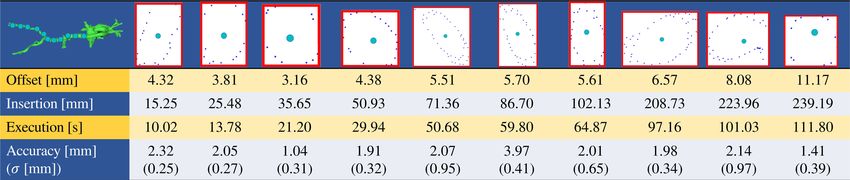
710                                                                                        IEEE ROBOTICS AND AUTOMATION LETTERS, VOL. 5, NO. 2, APRIL 2020

Fig. 5. Block diagram of the experimental setup: (a) During the pre-operative phase, an anatomical model is converted from a computed tomography (CT) scan
to an interactive point-cloud dataset (C ∈ Rm×3 ). (b) During intra-operative planning, a user selects target locations, which are fed to the path planning algorithm
(Algorithm 1), the region of interest (ROI) algorithm (Algorithm 2) and the actuation algorithm (Algorithm 3). (c) The setup shows the gelatine phantom model
!1 , with both manipulators (! 2 UR5 (RobUltra) and !    3 UR10 (RobARMM), Universal Robots, Odense, Denmark) in their initial configurations. The catheter
is inserted using the catheter insertion device (CID) ! 4 , while its tip can be either recognized or tracked on images obtained from the US transducer !      5 . The
transducer is controlled using a force-position hybrid controller with the aid of a force sensor (K3D40, Mesysteme AG, Henningsdorf, Germany) !       6 . A peristaltic
pump !  7 simulates blood flow within the phantom. Please refer to the accompanying video that describes the experimental setup and results.

   The returned pixel coordinates are then the matched template
coordinates. In the case where the catheter merely has to be
detected in order for autonomous insertion to continue, the
template matching algorithm can be adapted to a detection
algorithm by means of pixel intensity comparisons [29]. Each
pixel coordinate (sp ∈ R2 ) in the US slice is transformed to a
corresponding location (sv ∈ R2 ) in the coordinate frame {V}.
Finally, the catheter is deflected to the prescribed target using
the ARMM magnetic actuation strategy.

D. ARMM Actuation Strategy for Flexible Catheters
   In order to magnetically actuate an instrument, the ARMM
system requires knowledge of the RobARMM end-effector pose,                          coil so that p = pi is coincident with the coil symmetry axis
the magnetic field (B(p) ∈ R3 ) generated by the electromag-                         (ZC ∈ R3 : ||ZC || = 1) at all times [13]. We can express the
netic coil, as well as a point on the catheter tip (pc ∈ R3 ), at                    magnetic field at pi as
which the magnetic dipole (m ∈ R3 ) attached to the instrument
is located. Our actuation strategy (Algorithm 3) is to orient the                                          B(pi , Im ) = ZC B(xm , Im ),                         (15)
HEUNIS et al.: THE ARMM SYSTEM - AUTONOMOUS STEERING OF MAGNETICALLY-ACTUATED CATHETERS 711
TABLE I
THE RESULTS OF THE 10 EXPERIMENTS, WHEREIN THE CATHETER IS INSERTED INTO THE ARTERIAL PHANTOM, AND DEFLECTED TO PRESCRIBED 3D TARGETS.
THE RED BOUNDING BOXES INDICATE THE RECONSTRUCTED REGIONS OF INTEREST (ROIS) FOR EACH TARGET. THE STARTING OFFSET BEFORE DEFLECTION IS
SHOWN. NEXT, THE INSERTION LENGTH OF THE CATHETER AT THE TARGET AND THE CUMULATIVE EXECUTION TIME TO REACH THE REGION ARE INDICATED.
THIS IS FOLLOWED BY THE ACCURACY (AVERAGE DISTANCE BETWEEN THE TARGET AND THE CATHETER TIP), AND THE STANDARD
DEVIATION (σ) OF THE ACCURACY.
where Im ∈ R is the current input to the electromagnetic coil, An experiment is conducted using the block diagram shown
xm ∈ R+ is the distance from the dipole (on the catheter tip in Fig. 5. Within this experiment, a magnetic catheter is inserted
position) to the face of the coil, and B(xm , Im ) is the scalar into a phantom in order to reach a 3D target inside the arteries.
value of the magnetic field along the coil symmetry axis. Fluid flow within the artery is set to a speed of 17.6 cm/s.
We aim to influence the bending of the catheter by applying An end-user initializes the user interface associated with the
the external magnetic wrench, such that its tip moves towards the particular CT-data data of the phantom and selects a target in
desired location. With a prescribed offset distance, the coil pose 3D interactively on the point-cloud. This target is then sent to
with respect to the!catheter tip frame
"
is expressed in spherical the ARMM controller, which calculates the desired end-effector
coordinates (sm = xm θm φm ), defined as shown in Fig. 3. poses and trajectories for both the manipulators. This strategy is
We account for the distance (dic ) between the desired (pi (z, y)) repeated for 10 different targets.
and actual (pc (z, y)) catheter tip positions using a linear PI-
controller on the electromagnetic coil current, with feedback B. Results
provided by the US images.
To account for sudden position jumps, a filtered distance The results of all 10 trials are reported in Table I. During
(df,k ) between two points is obtained by the application of a the experiment, the catheter successfully reached the prescribed
first-order filter (using the discrete-time index k) on the esti- targets. The average targeting error between the tracked tip and
mated distance (dic ) - see Algorithm 3, Line 7. The proportional target positions is 2.09 ± 0.49 mm. These errors are slightly
error (eP,i ) and integral error (eI,i ) are calculated as shown in higher than previously reported ex-vivo results using similar
Algorithm 3, Line 8 and Line 9 respectively. We continuously magnetic actuation systems [5], [17]. However, the experiments
update the demand current for the electromagnetic coil (Line 10), presented therein either involved the deflection of a catheter
where KP and KI are proportional gains of the PI controller. in free air, or under the guidance of external cameras (which
Based on empirical tests, these gains are set to 0.12 A/mm and have a higher resolution than US, but nonetheless incompatible
0.05 A/mm2 . with clinical use). Next, a study with nearly identical equipment
than ours reported in vivo accuracies of 4.18 ± 1.76 mm under
IV. EXPERIMENTS electromagnetic guidance [18], which is less precise than the
method presented in this paper. Thus, the US-guided actuation
This section describes the experimental setup used to validate
method in the ARMM system is more promising and, moreover,
our proposed actuation strategy. Furthermore, it reports on the
achieves a stable maximum bandwidth of 30 Hz, which is higher
experimental results that were achieved to validate the overall
than that of similar actuation systems [8].
positioning accuracy of the ARMM system.
The process of acquiring a new US image and applying the
target tracking algorithm introduces an average latency of about
A. Experimental Setup
273 ms. A slice is acquired within 50 ms and target tracking
The poses of the manipulators and other objects within the needs approximately 230 ms, which suggests that most of the
ARMM workspace are monitored in real-time using the motion latency is due to transferring the images to the user interface
tracking system. Any movement within the system is registered for real-time display. Secondly, the median procedure time to
by the means of passive markers - retroreflective spheres that are reach via-points, and to stabilize the catheter tip at the 3D targets
triangulated by the surrounding cameras. We register all objects is 32.6 s. This is comparable to [18], who reported median
inside the ARMM workspace and derive the transformation of durations of 34.5 s using electromagnetic guidance, and 41.5 s
the coordinates from the tracking system reference frame to the using fluoroscopy images of an identic iliac vascular phantom.
global reference frame ({G}). Furthermore, we specify three The manipulators are both able to reach their prescribed poses at
additional frames - that of the US transducer tip ({U }), the US each via-point during the insertion. Consequently, autonomous
image plane ({S}) and the arterial phantom ({V}) (Fig. 3). insertion was achieved from the insertion point to the final target712 IEEE ROBOTICS AND AUTOMATION LETTERS, VOL. 5, NO. 2, APRIL 2020
at a 100% success rate, while full control of the catheter tip [8] C. Heunis, J. Sikorski, and S. Misra, “Flexible instruments for endovas-
was implemented at the final target. The hybrid force-position cular interventions: Improved magnetic steering, actuation, and image-
guided surgical instruments,” IEEE Robot. Autom. Mag., vol. 25, no. 3,
controller implemented on RobUltra resulted in a mean position pp. 71–82, Sep. 2018.
error of the transducer of 1.48 ± 0.65 mm and can move at a [9] N. Preda, A. Manurung, O. Lambercy, R. Gassert, and M. Bonfè, “Motion
maximum speed of 12 mm/s. We noticed that the accuracy in planning for a multi-arm surgical robot using both sampling-based algo-
rithms and motion primitives,” in Proc. IEEE/RSJ Int. Conf. Intell. Robots
the positioning was directly coupled to robustness in the tracking Syst., Hamburg, Germany, Sep. 2015, pp. 1422–1427.
algorithm, which is limited to the imaging depth (90 mm) of the [10] Abbou et al., “Laparoscopic radical prostatectomy with a remote con-
L14-5 transducer. trolled robot,” J. Urology, vol. 197, no. 2, pp. S210–S212, 2017.
[11] L. B. Kratchman, T. L. Bruns, J. J. Abbott, and R. J. Webster, “Guid-
ing elastic rods with a robot-manipulated magnet for medical ap-
V. CONCLUSIONS & FUTURE WORK plications,” IEEE Trans. Robot., vol. 33, no. 1, pp. 227–233, Feb.
2017.
This study investigates the benefits of a model-free catheter- [12] P. R. Slawinski, A. Z. Taddese, K. B. Musto, K. L. Obstein, and P. Valdastri,
ization approach for a novel magnetic actuation system. In this “Autonomous retroflexion of a magnetic flexible endoscope,” IEEE Robot.
Autom. Lett., vol. 2, no. 3, pp. 1352–1359, Jul. 2017.
approach, a magnetic endovascular catheter is guided towards [13] J. Sikorski, C. M. Heunis, F. Franco, and S. Misra, “The ARMM system: An
and positioned at user-defined targets inside an arterial phantom, optimized mobile electromagnetic coil for non-linear actuation of flexible
while relying on US images. The methods presented in this surgical instruments,” IEEE Trans. Magn., vol. 55, no. 9, Sep. 2019,
Art. no. 5600109.
study could allow clinicians with limited experience to insert [14] S. L. Charreyron, B. Zeydan, and B. J. Nelson, “Shared control of a
and position endovascular catheters within the human body at magnetic microcatheter for vitreoretinal targeted drug delivery,” in Proc.
average positioning errors of 2.09 ± 0.49 mm. IEEE Int. Conf. Robot. Autom., May, 2017, pp. 4843–4848.
[15] Jeong et al., “Feasibility study on magnetically steerable guidewire device
In our future work, we plan to reduce positioning errors that for percutaneous coronary intervention,” Int. J. Control, Autom. Syst.,
may result from angular displacements within pulsating fluid vol. 15, pp. 473–479, 2017.
flow. This can be accounted for either by employing adaptive [16] L. Yang, X. Du, E. Yu, D. Jin, and L. Zhang, “Deltamag: An
electromagnetic manipulation system with parallel mobile coils,” in
control methods or by means of independent magnetic field Proc. IEEE Int. Conf. Robot. Autom., Montreal, Canada, May, 2019,
and gradient control, as discussed in [13]. Next, we plan to pp. 9814–9820.
demonstrate the ARMM actuation strategy in a tele-operative [17] J. Edelmann, A. J. Petruska, and B. Nelson, “Magnetic control of contin-
uum devices,” Int. J. Robot. Res., vol. 36, no. 1, pp. 68–85, 2017.
manner which, in practice, would further reduce the risks im- [18] F. Manstad-Hulaas, G. A. Tangen, L. G. Gruionu, P. Aadahl, and
posed by both intermittent X-ray scans during an intervention T. A. Hernes, “Three-dimensional endovascular navigation with electro-
and prolonged catheterization durations. A real-time vessel magnetic tracking: Ex vivo and in vivo accuracy,” J. Endovascular Therapy,
vol. 18, no. 2, pp. 230–240, 2011.
tracking method of the target arteries, while compensating for [19] A. J. Petruska and J. J. Abbott, “Optimal permanent-magnet geometries
breathing-induced motions should be incorporated. Finally, we for dipole field approximation,” IEEE Trans. Magn., vol. 49, no. 2,
will develop improved catheter detection and tracking algo- pp. 811–819, Feb. 2013.
[20] Yoshida et al., “Blood-mimicking fluid for the doppler test objects of
rithms by reducing acoustic clutter and improving the resolution medical diagnostic instruments,” in Proc. IEEE Int. Ultrasonics Symp.,
of the US images. Consequently, it could aid with reconstructing Dresden, Germany, Oct. 2012, pp. 1–4.
arteries within non-homogeneous environments and allow for [21] D. Holz, A. E. Ichim, F. Tombari, R. B. Rusu, and S. Behnke, “Regis-
tration with the point cloud library: A modular framework for aligning
improved control over both insertion and positioning. in 3-D,” IEEE Robot. Autom. Mag., vol. 22, no. 4, pp. 110–124, Dec.
2015.
REFERENCES [22] P. Chatelain, A. Krupa, and N. Navab, “Optimization of ultrasound image
quality via visual servoing,” in Proc. IEEE Int. Conf. Robot. Autom.,
[1] K Abdelaal et al., “4Fr in 5Fr sheathless technique with standard catheters Seattle, USA, May 2015, pp. 5997–6002.
for transradial coronary interventions: Technical challenges and persisting [23] V. Chougule, A. Mulay, and B. B Ahuja, “Conversions of CT scan images
issues,” Catheterization Cardiovascular Interv., vol. 85, no. 5, pp. 809– into 3D point cloud data for the development of 3D solid model using
815, 2015. B-Rep scheme,” in Proc. Int. Conf. Precision, Meso, Micro Nano Eng.,
[2] Health Quality Ontario, “Coil embolization for intracranial aneurysms: An Calicut, India, Dec. 2013, pp. 630–635.
evidence-based analysis,” Ontario Health Technol. Assessment Ser., vol. 6, [24] K. Mathiassen, J. E. Fjellin, K. Glette, P. K. Hol, and O. J. Elle, “An
no. 1, pp. 1–114, 2006. ultrasound robotic system using the commercial robot UR5,” Frontiers
[3] M. Ikhsan, K. K. Tan, and A. S. Putra, “Assistive technology for ultrasound- Robot. AI, vol. 3, pp. 1–16, 2016.
guided central venous catheter placement,” J. Med. Ultrason., vol. 45, no. 1, [25] S. Chiaverini, B. Siciliano, and O. Egeland, “Review of the damped
pp. 41–57, 2018. least-squares inverse kinematics with experiments on an industrial
[4] A. Hernandez-Vela et al., “Accurate coronary centerline extraction, caliber robot manipulator,” IEEE Trans. Control Syst. Technol., vol. 2, no. 2,
estimation, and catheter detection in angiographies,” IEEE Trans. Inf. pp. 123–134, Jun. 1994.
Technol. Biomedicine, vol. 16, no. 6, pp. 1332–1340, Nov. 2012. [26] B. Ihnatsenka and A. P. Boezaart, “Ultrasound: Basic understanding and
[5] J. Sikorski, A. Denasi, G. Bucchi, S. Scheggi, and S. Misra, “Vision-based learning the language,” Int. J. Shoulder Surgery, vol. 4, no. 3, pp. 55–62,
3D control of magnetically actuated catheter using BigMag - an array of 2010.
mobile electromagnetic coils,” IEEE/ASME Trans. Mechatronics, vol. 24, [27] R. M. Murray, A Mathematical Introduction to Robotic Manipulation.
no. 2, pp. 505–516, Apr. 2019. Boca Raton, FL, USA: CRC Press, 2017, pp. 27–29.
[6] B. Véron, A. Hubert, J. Abadie, and N. Andreff, “Geometric analysis of [28] Z. Pan and X. Wang, “Correlation tracking algorithm based on adaptive
the singularities of a magnetic manipulation system with several mobile template update,” in Proc. 3rd Int. Congr. Image Signal Process., Yantai,
coils,” in Proc. IEEE/RSJ Int. Conf. Intell. Robots Syst., Tokyo, Japan, China, Oct. 2010, pp. 98–101.
Nov. 2013, pp. 4996–5001. [29] N. Markus, Mi. Frljak, I. S. Pandzic, J. Ahlberg, and R. Forchheimer, “A
[7] J. Rahmer, C. Stehning, and B. Gleich, “Remote magnetic actuation using method for object detection based on pixel intensity comparisons,” in Proc.
a clinical scale system,” PloS ONE, vol. 13, no. 3, pp. 1–19, 2018. 2nd Croatian Comput. Vision Workshop, 2013, pp. 1–5.You can also read