The elastic-plastic properties of an anti-icing coating on an aluminum alloy: Experimental and numerical approach - De Gruyter
←
→
Page content transcription
If your browser does not render page correctly, please read the page content below
Journal of the Mechanical Behavior of Materials 2021; 30:1–8

Research Article

Wei Zhang, Sheng-Li Lv, Xiaosheng Gao, and Tirumalai S. Srivatsan*

The elastic-plastic properties of an anti-icing
coating on an aluminum alloy: Experimental and
numerical approach
https://doi.org/10.1515/jmbm-2021-0001                              to decreasing cost while concurrently enhancing perfor-
Received Sep 10, 2020; accepted Jan 20, 2021                        mance [1, 2]. Therefore, there does exist a need to carry out
                                                                    research that is aimed at conducting a performance test
Abstract: In this paper, an attempt is made to describe the
                                                                    on a hydrophobic coating that is often chosen for use on
method that combines the results obtained from nanoin-
                                                                    an aircraft structure [3]. Up until now a survey of the me-
dentation experiment with finite element simulation to
                                                                    chanical testing methods, published in the open literature,
determine or establish the elastic-plastic properties of a
                                                                    reveals a few of the methods to be both suitable and appro-
super-hydrophobic anti-icing coating. The nanoindenta-
                                                                    priate for coatings that offer a combination of properties.
tion test was conducted and elastic properties of the coat-
                                                                    The test methods are the following: (i) stretching method,
ing, to include elastic modulus and hardness were obtained.
                                                                    (ii) scratch test method, (iii) nanoindentation method, (iv)
The plastic properties, to include yield stress, monotonic
                                                                    laser scratch method, and (v) wedge loading method [1–3].
strength coefficient and monotonic strain hardening expo-
                                                                    Each of these test methods are fairly well known for both
nent, were obtained using an inverse, iterative method of
                                                                    the advantages and disadvantages they have to offer, which
experimental measurement in synergism with finite ele-
                                                                    makes them an appropriate choice for selection and use in
ment simulation. This approach, which is a combination of
                                                                    a spectrum of relevant applications [4–6]. The technique of
experimental data obtained from the nanoindentation test
                                                                    nanoindentation is by far the most popular and preferen-
and results obtained from numerical finite element simula-
                                                                    tially chosen method for the purpose of not only determin-
tion, was found to be effective for determining mechanical
                                                                    ing but also understanding the mechanical properties of
properties of the chosen coating.
                                                                    a coating. Since the technique of nanoindentation is both
Keywords: hydrophobic coating, nanoindentation, finite easy to implement and does not cause any observable dam-
element simulation, elastic-plastic properties                      age to the material, it has been increasingly preferred and
                                                                    chosen for the study of both micro-mechanical properties
                                                                    and nano-mechanical properties of a coating [7, 8]. Infor-
                                                                    mation specific to both the elastic modulus and hardness of
1 Introduction
                                                                    a coating can be obtained from use of the nanoindentation
                                                                    test technique. However, the technique of nanoindentation
The presence of a hydrophobic coating on the surface of
                                                                    is not easily applicable under a few conditions. These condi-
an aluminum alloy skin used in aircraft structures does
                                                                    tions include the presence of ‘local’ stress distribution and
aid in preventing the formation of ice while concurrently
                                                                    stress concentration. Also, the stress versus strain response
minimizing drag and contributing in an observable way
                                                                    and resultant properties of the coating cannot be easily ob-
                                                                    tained by use of the nanoindentation test technique [9].
                                                                          With continuing developments in the domain of nu-
*Corresponding Author: Tirumalai S. Srivatsan: Department
of Mechanical Engineering, The University of Akron, Akron, Ohio
                                                                    merical    simulation technology, sustained advances have
44325, United States of America; Email: tsrivatsan@uakron.edu       made    it possible to enable numerical simulation of the mi-
Wei Zhang: National Key Laboratory of Science and Technology on crostructure with the primary and only intent of obtaining
UAV, Northwestern Polytechnical University, Xi’an 710072, China;    the mechanical properties of a coating. One such numeri-
School of Aeronautics, Northwestern Polytechnical University, Xi’an cal method, the finite element method (FEM), has in recent
710072, China
                                                                    years, i.e., since the early 1980s, been preferentially chosen
Sheng-Li Lv: National Key Laboratory of Science and Technology on
UAV, Northwestern Polytechnical University, Xi’an 710072, China     and used for studying the mechanical properties of materi-
Xiaosheng Gao: Department of Mechanical Engineering, The            als, structures and coatings [10–13]. Among the FEM tech-
University of Akron, Akron, Ohio 44325, United States of America

  Open Access. © 2021 W. Zhang et al., published by De Gruyter.         This work is licensed under the Creative Commons Attribution 4.0
License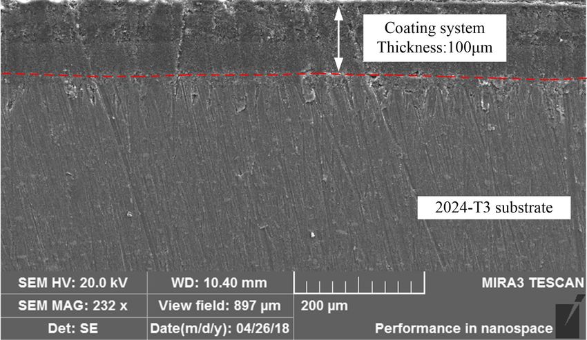
2 | W. Zhang et al.

niques, the ABAQUS software is widely used in material per-        the basic structure of the chosen coating and the ‘key’ per-
formance analysis [14]. Use of the numerical finite element        formance parameters that exist at the coating-substrate
technique is a good supplement to the nanoindentation              interface. Also, based on experimental data obtained from
method and the two can be combined to obtain mechanical            the nanoindentation test, the elastic-plastic properties of
properties of a coating. For example, the plastic properties       the chosen coating were determined by use of a combina-
of a coating can be obtained through a synergism of the            tion of finite element simulation and results obtained from
nanoindentation test and finite element simulation while           the nanoindentation test.
concurrently obtaining the stress versus strain response of
the coating [8, 15].
    In their novel research study, Hyun and co-workers [16]
simulated the double indentation test using a conical in-
                                                                   2 Experimental procedure
denter with the finite element method by simplifying and
deducing a relationship to exist between the following:            2.1 Specimen preparation
   (i) contact radius of the indenter and indenter angle,          It is both important and essential to prepare the surface of
  (ii) arc radius at the tip of the chosen indenter,               the test sample prior to initiating the indentation measure-
 (iii) material properties.                                        ment at the nanoscale level. Test samples (10-mm × 10-mm
      A prediction of both the yield strength (σ YS ) and hard-    × 2-mm) were precision cut from the super-hydrophobic
ening exponent (n) of the chosen material was made pos-            anti-icing coated plate. This was followed by grounding
sible by use of this approach. In their study, Hyun and co-        using 500, 1000, 1500, and 2000 grit abrasive papers, then
workers [16] also documented noticeable differences to exist       ultrasonically cleaned for 15 min. The test samples were
between the results obtained from simulation using a three-        then thoroughly cleaned by immersion in alcohol to remove
dimensional Berkovich indenter and simulation using a              any and all impurities present on the surface and placed
two-dimensional conical indenter. Other related and rele-          in an environment box to ensure drying. The cleaned sam-
vant research studies have attempted to study and record           ples were then observed in a scanning electron microscope
the findings from: (i) finite element analysis of a layered        (SEM) [Model: TEXCAN (Czechoslovakia) MIRA3 XMU] for
elastic solid in normal contact with a rigid substrate [17],       the following: (i) morphology of intrinsic microstructural
(ii) the stress distribution that occurs during sliding con-       features, and (ii) the presence and distribution of impurities
tact of a double coating system [18], and (iii) use of the         on the coating surface, which could contribute to erroneous
numerical simulation technique to establish the maximum            results for the hardness at the nano-level. It can be clearly
contact pressure that can occur at the coating-matrix inter-       seen that there are easily identifiable layers (red dotted
face under the influence of Hertzian pressure [19]. Even the       lines) in the coating as shown in Figure 1. The thickness of
interlayer stress for a titanium / titanium nitride [Ti / TIN]     the chosen coating was around 100 µm.
coating that was prepared by magnetron physical deposi-
tion was precision determined and the findings compared
with the experimental results [20]. Several of these stud-
ies aimed at determining the mechanical properties of the
coating-substrate interface were focused predominantly on
theoretical analysis, with the interface between two coat-
ings and/or the coating and the substrate being simplified
to be a thin layer for the purpose of ease in analysis [21, 22].
      In this research paper, the results of a recent study on
super hydrophobic coatings that show much promise for
selection and use in emerging civilian aircraft is presented
and briefly discussed. The substrate material chosen was
sheet of aluminum alloy 2024-T3, which is the preferred            Figure 1: Scanning electron micrograph depicting the microstruc-
material, [i.e., aluminum alloy] for use as aircraft skin. The     tures at the interface of the aluminum alloy (2024-T3) substrate and
microstructure, surface morphology and interfacial struc-          the coating
ture of the super-hydrophobic ice-proof coating was ob-
served and characterized using a scanning electron micro-
scope. This enabled in establishing an understanding of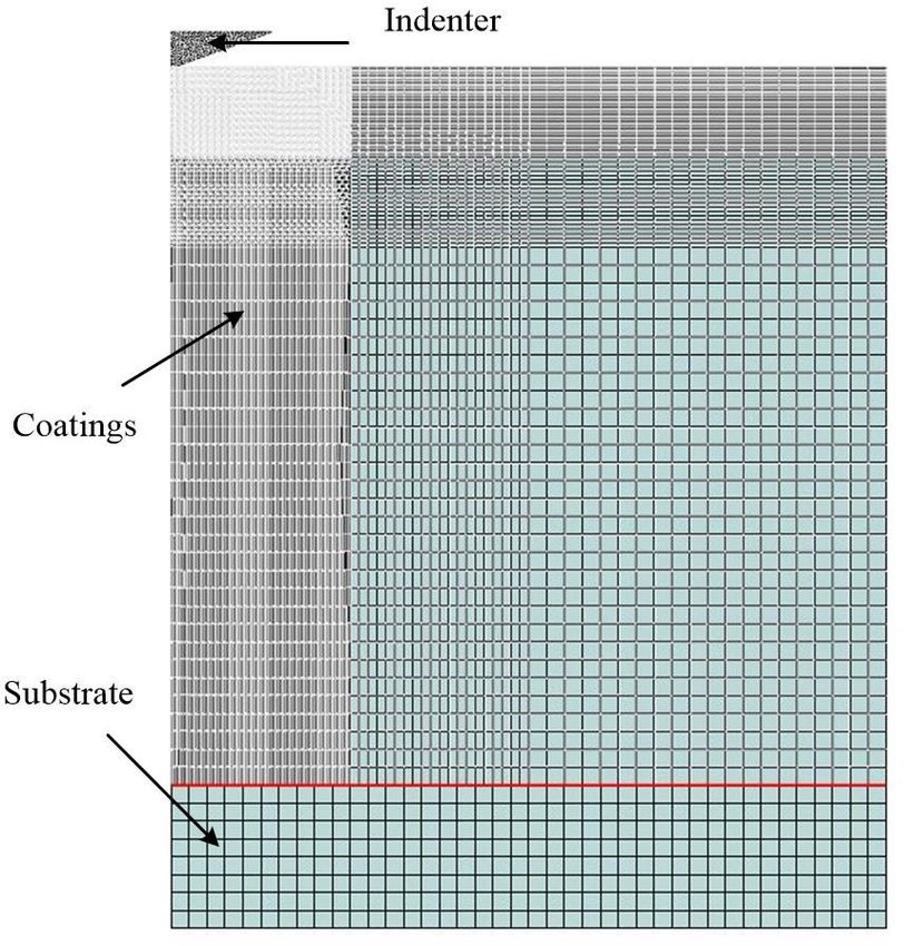
The elastic-plastic properties of an anti-icing coating on an aluminum alloy | 3
2.2 Nanoindentation experiment scopically nonlinear. The relationship between P and h can
be expressed as a function as follows [9]
The surface microstructure of the chosen coating was ob-
served, step by step, from low magnification to high mag- P = C(h2 ) (1)
nification. An observation of the surface of the coating re-
In this expression, P is the load, C is curvature of the load-
vealed it to be essentially compact with the absence of voids,
ing curve and h is measure of depth of indent into the sur-
scratches and other fine microstructural-related defects. A
face of the chosen coating. The curvature value of C was
smooth surface does help in obtaining accurate results from
obtained by data fitting and is equal to 0.00394. Subse-
the nanoindentation test.
quent to the nanoindentation test, the morphology of the
The values of elastic modulus [E] and hardness [H]
indent was observed using in-situ scanning probe imaging
of the chosen anti-icing coating was measured using the
(SPM). A 3-D morphology of the coating was obtained. Over-
technique of nanoindentation. A nano-mechanical tester
all morphology of the surface of the indent was observed
[Model: Hysteron TI950] was used for the experiments. The
to be “concave”. The surface morphology of the coating im-
maximum pressure during the indentation experiment was
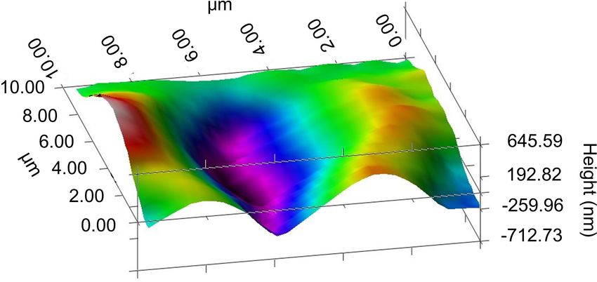
mediately following nanoindentation is shown in Figure 3.
2700 µN based on the material chosen and used for the
The height value at the bottom of the concave is −712.73nm
coating, and the maximum displacement value for the ex-
(in purple).
periment was set to 3000 nm. Since overall thickness of the
coating is less than 100 µm the displacement that occurs
during loading was noticeably less than 10 percent of the
coating thickness.
3 Elastic properties
The experimental results are shown in Figure 2. Six points
on the flat surface of the test sample were randomly se-
lected for the purpose of indentation. Load control was
Figure 3: Profile showing morphology of the indent on the coating
used during the experiment and when the load reached surface subsequent to unloading
2700 µN, a load holding phase starts as is evident from
the straight portion of the force versus displacement curve.
This was followed by the unloading phase. From the figure The experimental results are summarized in Table 1,
is seen the existence and occurrence of indentation creep where E represents the elastic modulus and H represents
at the fine microscopic level. The loading curve is micro- the hardness. The elastic modulus (E) and hardness [H]
values were calculated from slope of the loading curve and
the unloading curve very much in conformance with the
method provided and recommended by Oliver and Pharr [9].
The duplicate measurement results at each point of the
nanoindentation test revealed minimum scatter. To min-
imize and/or eliminate scatter in the test data, all of the
Table 1: Summary of results obtained from the nanoindentation
tests
Number Pmax (µN) E (GPa) H (GPa)
1 2700 4.046 0.187
2 2700 3.580 0.168
3 2700 5.027 0.217
4 2700 3.587 0.175
Figure 2: Force versus displacement curves obtained from the 5 2700 3.824 0.169
nanoindentation tests 6 2700 3.505 0.165
4 | W. Zhang et al.

outliers were excluded by use of the criterion put forth by        dentation test. Thus, is made possible a fairly accurate de-
Grubb [23].                                                        termination of the elastic-plastic properties of the chosen
    Let G n represent the Grubbs value for the measurement         anti-icing coating.
made at point n. This can then be defined as                           The finite element model [FEM] used to simulate
                                                                   nanoindentation test considers the following aspects:
                  G n = [X(n) − (X)average /S]              (2)
                                                                     (a) The geometric model and boundary conditions
In this expression X(n) represents the measured value,                   should represent the experimental nanoindentation
X average is the mean value, and S is the standard devia-                test while correctly establishing the two key geomet-
tion. From the six measured values provided in Table 1, the              ric parameters, namely: (i) coating thickness, and (ii)
mean value of the elastic modulus [E] is 3.94 GPa with a                 radius of head of the chosen indenter.
standard deviation (S) of 0.5290.                                    (b) The mechanical properties of the substrate, coating
     Let G (α, m) be the critical value of Grubb with α being            and indenter to include elastic modulus [E], Pois-
the significance level and ‘m’ being the number of measure-              son’s ratio [ν], and stress versus strain relationship
ments made. For the six measurements made, the critical                  that governs plastic response. For this the materials
value of Grubb is G (0.01, 6) = 1.944. The average value                 chosen for both the substrate (aluminum alloy) and
for elastic modulus (E) of the coating was found to be 3.92              the coating are considered to be essentially isotropic.
GPa. The average value for hardness [H] for the coating              (c) An interaction between the contact surfaces.
was calculated to be 169 MPa. The results obtained reveal
                                                                        For the finite element simulation, a “local” model was
elastic modulus (E) of the chosen coating to be equivalent
                                                                   built around the chosen indenter, which includes the inden-
to that of a polymer-based material.
                                                                   ter, coating, and substrate. The Berkovich indenter used
                                                                   in the nanoindentation experiment was simulated to be
                                                                   a cone having a half-apex angle of 70.32∘ [12, 24]. Due to
4 An evaluation of elastic-plastic                                 symmetry, an axisymmetric model was established by com-
                                                                   bining the load and boundary conditions of the coating
  properties and discussion                                        during the experiment. The thickness of the substrate was
                                                                   20µm and thickness of the chosen coating was 100µm.
In the previous section, the material parameters, namely
                                                                        For the finite element simulation, the following as-
elastic modulus [E], and hardness [H] of the chosen coat-
                                                                   sumptions were made [8, 15]:
ing, were obtained using the nanoindentation test. How-
ever, its plastic properties remain unknown. Therefore, us-           (i) The coating-substrate interface is completely bonded
ing a combination of finite element (FE) simulation and                   with an absence of slip, and
the nanoindentation experiment the plastic portion of the            (ii) Friction between the contacting surfaces of the in-
stress versus strain curve is obtained by using the inverse,              denter and the coating is neglected.
iterative method. For this study, the anti-icing coating is as-        The elastic properties of the indenter, coating and alu-
sumed to be essentially isotropic. Following an initial linear     minum alloy substrate are summarized in Table 2. From
elastic stage, it obeys a power-law hardening stress versus        the results, it was found that both the indenter and the
strain relationship, which is expressed as follows [8, 9].         aluminum alloy substrate remain in the elastic region dur-
                          {︃                                       ing the entire process. The coating was considered to be
                             Eϵ,   σ < σy
                     σ=                                     (3)    an isotropic, elastic-plastic material that obeys the stress
                               n
                             Kϵ , σ ≥ σ y                          versus strain relationship given by Equation (3). The val-

In this expression: (i) E represents the elastic modulus, (ii)
σ y is the yield stress, (iii) K is the monotonic strength coef-   Table 2: Elastic properties of the materials
ficient, and (iv) n is the strain hardening exponent. By vary-
ing the values of the strength coefficient (K) and strain hard-         Material            Elastic modulus       Poisson’s ratio
ening exponent (n) in the finite element simulation and by                                      E (GPa)                 (ν)
comparing the resultant load versus displacement curve               Indenter [15]                1141                 0.07
with experimental measurements, the plastic properties                  Coating                   3.62                 0.25
of the chosen anti-icing coating is obtained when results              Substrate                  73.1                 0.3
provided by the finite element (FE) simulation agree well          [Aluminum alloy]
with the experimental results obtained from the nanoin-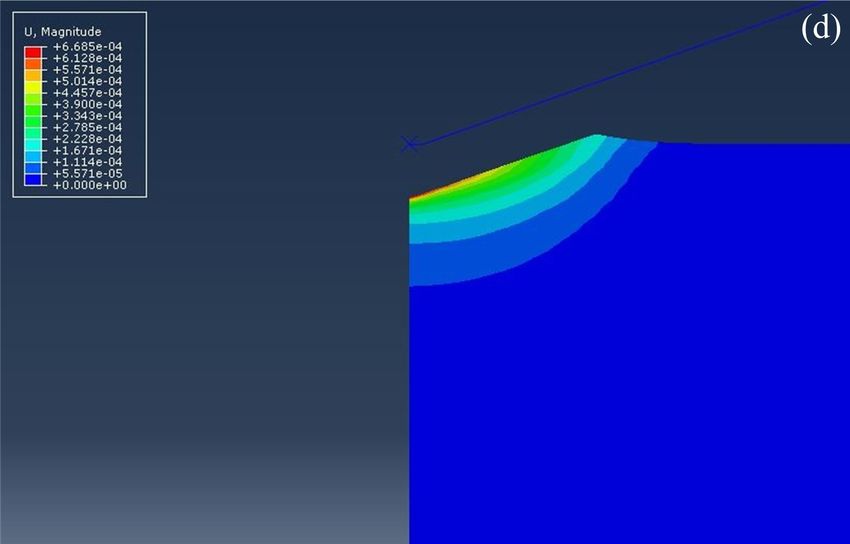
The elastic-plastic properties of an anti-icing coating on an aluminum alloy | 5
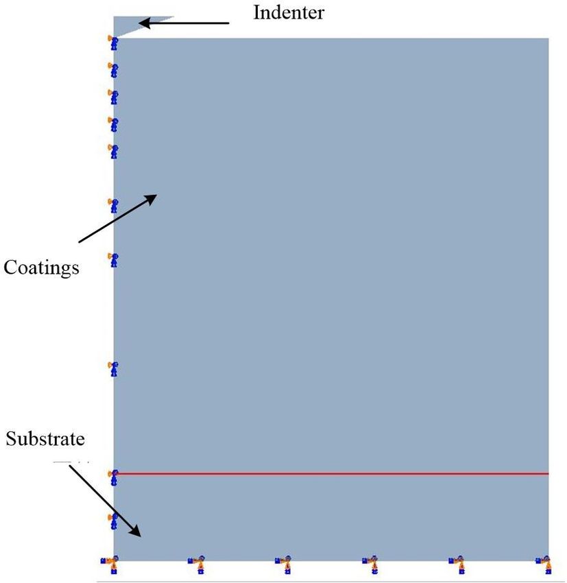
Figure 4: A schematic showing the boundary conditions used for
Figure 5: A schematic showing the mesh division used in the finite
purpose of computation
element simulation
ues of plastic parameters of the chosen coating were deter-
mined using the inverse, iterative method by comparing
the finite element computed curve with the measured load-
displacement curve obtained from the nanoindentation
test.
The boundary conditions are prescribed such that bot-
tom of the substrate is fixed, and an axisymmetric condition
is imposed along the axis of symmetry. This is shown in
Figure 4. A load is then applied to the indenter, in incre-
mental stages, such that the model can simulate both the
loading process and the unloading process specific to the
nanoindentation experiment.
The finite element software ABAQUS was used for the
purpose of simulation, and the CAX4I element was chosen
and used to generate the mesh. The finite element mesh Figure 6: A comparison of the simulation curve with the experimen-
is refined in the immediate vicinity of the indent due to tal curve
the occurrence of high stress and resultant deformation
gradients in this region. A coarser mesh was used in the convincing indication for the occurrence of a converged
region away from the indent. The overall partition of the solution for the mesh configuration chosen.
mesh is shown in Figure 5. Next, a series of finite element simulations were con-
At first, a convergence study was conducted to ensure ducted using different values of monotonic strength coef-
that a refinement in the mesh chosen is both adequate and ficient (K) and strain hardening exponent (n) for the cho-
sufficient for the purpose of this research study. To meet sen coating. The computed load versus displacement curve
this objective three meshes, each consisting of: (i) 7250 was compared with the experimental curve, as shown in
elements, (ii) 8400 elements, and (iii) 9020 elements, were Figure 6. The value of strength coefficient (K) and strain
generated. Following computation, it was found that the hardening exponent (n) that results in the best fit between
load versus displacement curve for each of the three chosen the finite element computed curve and the experimental
meshes differ by less than one percent. This provides a curve obtained from the nanoindentation test was taken to
be the strength coefficient (K) and strain hardening expo-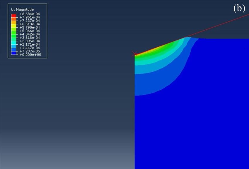
6 | W. Zhang et al.

 (a) Stress distribution at an indentation depth of 860 nm           (b) Strain distribution at an indentation depth of 860 nm

 (c) Stress distribution following unloading                           (d) Strain distribution subsequent to unloading

Figure 7: Contours of von Mises stress and equivalent strain during loading and unloading processes

nent (n) of the coating. Based on the stress versus strain                 During unloading, due to elastic-plastic properties of
curve the yield strength (σ y ) was obtained. The plastic pa-         the chosen coating, the severity of deformation that occurs
rameters for the chosen anti-ice coating were found to be             at location of the indent decreases but does not completely
the following: (i) Yield strength (σ y ) = 15 MPa, (ii) strain        disappear. As shown in Figure 7(c) and Figure 7(d), the
hardening exponent (n) = 0.75, and (iii) Strength coefficient         residual stress was 20.58 MPa and the depth following un-
(K) = 918.45 MPa.                                                     loading was 668 nm. The value of residual stress exceeds
     In Figure 7 is shown the contours for the von Mises              the yield strength of the chosen coating providing a con-
stress and equivalent strain induced in the chosen coat-              vincing indication of the occurrence of highly “localized”
ing. The von Mises stress contour for an indentation depth            plastic deformation. Comparing one-to-one, the results ob-
of 860 nm is shown in Figure 7a. The stress is high near              tained from the nanoindentation experiment, it was found
the center of the indent and gradually decreases as dis-              that results of the finite element simulation are consistent
tance from the indent increases. The maximum von Mises                with the experimental results.
stress was found to be 22.94 MPa. This value is greater than
yield strength (σ YS ) of the chosen coating. Hence, the occur-
rence of plastic deformation both at and near the indenter
is evident. The strain contour for gradual loading up to the
                                                                      5 Conclusions
maximum displacement is shown in Figure 7(b). Maximum
                                                                      In accordance with characteristics of a super-hydrophobic
deformation was found to occur immediately below the
                                                                      anti-icing coating, the nanoindentation test was deter-
indenter.
                                                                      mined to be an ideal experimental approach. The inverse,
                                                                      iterative method was used to obtain plastic properties of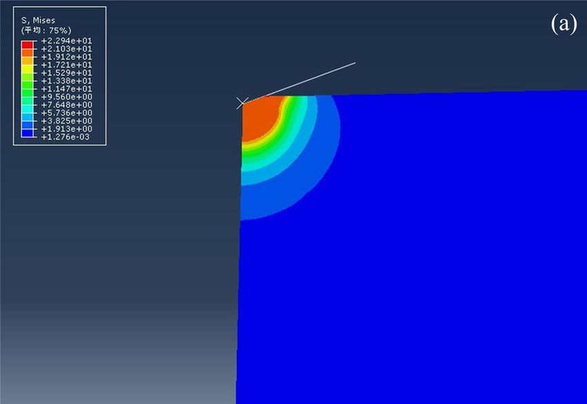
The elastic-plastic properties of an anti-icing coating on an aluminum alloy       | 7

the chosen coating. The key findings of this research study              [3]    Paul D. D Dolatabadi., Effect of Super Hydrophobic Coating on
are the following:                                                              the Anti-Icing and Deicing of an Airfoil. J Aircr. 2017;54(2):490–9.
                                                                         [4]    Kash L. Mittal., Adhesion measurements of films and coatings.
      1. Based on results of the nanoindentation experiments,                   2nd ed. CRC Press; 2001.
         the elastic modulus [E] of the hydrophobic coating              [5]    Malzbendera J. Measuring the mechanical properties of coatings:
         was 3.62 GPa with an average hardness [H] of 169                       a methodology applied to nano-particle-filled sol–gel coatings
         MPa. The plastic behavior of the coating cannot                        on glass. Mater Sci Eng Rep. 2002;36(2-3):47–103.
                                                                         [6]    Tabatabaei M, Shodja HM. A combined first principles and Mohr-
         be obtained using the nanoindentation experiment.
                                                                                Coulomb criterion for the determination of the nanohardness of
         The finite element method was used to simulate the                     amorphous silicon. J Mech Behav Mater. 2015;24(5-6):145–51.
         nanoindentation process. In combination with exper-             [7]    Mallikarjunachari G, Ghosh P. Analysis of strength and response
         imental results, the power law hardening model was                     of polymer nano thin film interfaces applying Nanoindentation
         used to represent the stress versus strain relation-                   and nano scratch techniques. Polymer (Guildf). 2016;90:53–66.
                                                                         [8]    Yang Y, Liao N, Zhang M, Li F. Evaluation of the elastic-plastic
         ship of the chosen coating. The plastic parameters
                                                                                properties of SiC coating system by finite element simulations’.
         were obtained using the inverse iterative method. The                  J Eur Ceram Soc. 2017;37(13):3891–7.
         plastic parameters for the chosen coating were found            [9]    Oliver WC, Pharr GM. An improved technique for determining
         to be the following: (i) yield strength (σ y ) is 15 MPa,              hardness and elastic modulus using load and displacement sens-
         (ii) strain hardening exponent (n) is 0.75, and (iii)                  ing indentation experiments. J Mater Res. 1992;7(6):1564–83.
         monotonic strength coefficient (K) is 918.45 MPa.               [10]   Shi R, Nie Z, Fan Q, Li G. Elastic plastic deformation of TC6 tita-
                                                                                nium alloy analyzed by in-situ synchrotron-based X-ray diffrac-
      2. Finite element simulation revealed the occurrence
                                                                                tion and microstructure based finite element modeling. J Alloys
         of plastic deformation both at and near the region of                  Compd. 2016;688:788–92.
         the indent. Even subsequent to unloading the local-             [11]   Kang JJ, Becker AA, Sun W. Determining elastic–plastic properties
         ized plastic deformation persists in the region of the                 from indentation data obtained from finite element simulations
         indent with the residual stress exceeding the yield                    and experimental results. Int J Mech Sci. 2012;62(1):34–46.
                                                                         [12]   Yang Y. Study on mechanical behavior of coating-substrate based
         strength (σ YS ) of the chosen coating.
                                                                                on finite element modeling. PhD thesis. Wenzhou university of
      3. This study clearly shows that by combining the                         China, Wenzhou, China; 2017. (in Chinese)
         nanoindentation test with finite element simulation,            [13]   Gupta AK, Porwal D, Dey A, Sridhara N, Mukhopadhyay AK,
         it is possible to obtain the elastic-plastic properties                Sharma AK, et al. Evaluation of elastic-plastic properties of ITO
         of the chosen coating.                                                 film using combined Nanoindentation and finite element ap-
                                                                                proach. Ceram Int. 2016;42(1):7225–33.
                                                                         [14]   Allali A, Belbachir S, Alami A, Boucham B, Lousdad A. Sadia Bel-
Acknowledgement: The authors would extend abundance
                                                                                bachir., Ahmed Alami., Belhadj Boucham., Abdelkader Lousdad.,
of thanks and appreciation to Mr. Yong Liu for providing                        The effect of the outlet angle β2 on the thermomechanical be-
valuable assistance with the finite element simulation.                         havior of a centrifugal compressor blade. J Mech Behav Mater.
                                                                                2020;29(1):1–8.
Funding information: This research was financially sup-                  [15]   Yang Y, Liao N, Zhang M, Li F. Numerical investigation on the
                                                                                bond strength of a SiC-based multi-layer coating system. J Alloys
ported by Program 41402020401.
                                                                                Compd. 2017;710:468–71.
                                                                         [16]   Hyun HC, Kim MS, Lee JH, Lee H. A Conical Indentation Technique
Authors contribution: All authors have accepted responsi-                       Based on FEA Solutions for Property Evaluation. Mech Mater.
bility for the entire content of this manuscript and approved                   2011;43(6):313–31.
its submission.                                                          [17]   Komovopoulus K. Finite element analysis of a layered elastic
                                                                                solid in normal contact with a rigid substrate. J Tribol-T Asme.
                                                                                1988;110(3):477–85.
Conflict of interest: The authors state no conflict of inter-
                                                                         [18]   Tian H, Saka N. Finite element analysis of an elastic-plastic two-
est.                                                                            layered half-space: sliding contact. Wear. 1991;148:262–85.
                                                                         [19]   Diaod K. Interface yield map of a hard coating under sliding
                                                                                contact. Thin Solid Films. 1994;245(1-2):115–21.
                                                                         [20]   Dobrzanski LA, Sliwa A, Kwasny W. Employment of the finite ele-
References                                                                      ment method for determining stresses in coatings obtained on
                                                                                high-speed steel with the PVD process. J Mater Process Technol.
[1]    Morita K, Gonzales J, Sakaue H. Effect of PTFE Particle Size on          2005;164:1192–6.
       Superhydrophobic Coating for Supercooled Water Prevention.        [21]   Zhang Y. Kong de-Jun., Study on the determination of interfacial
       Coatings. 2018;8(12):1–9.                                                binding strength of coatings(I): theoretical analysis of stress in
[2]    Karapanagiotis I, Manoudis P. Superhydrophobic surfaces. J               thin film binding interface. Acta Phys Sin-Ch Ed. 2006;6:2897–
       Mech Behav Mater. 2012;21(1-2):21–32.                                    900.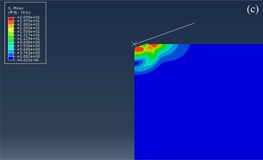
8 | W. Zhang et al.

[22] Song YS. Yao Shu-ren., Adhesive Between Organic Coating and         [24] Ma ZS. Characterization of the mechanical properties of metallic
     Metal Substrate [in Chinese] Mater Prot. 1999;32:21–2.                   films by Nanoindentation method. PhD thesis. Xiangtan Univer-
[23] Standardization Administration of the People’s Republic of China.        sity of China, Xiangtan; 2011. (in Chinese)
     GB/T 4883-2008 Statistical Interpretation of Data – Detection
     and Treatment of Outliers in the Normal Sample. Beijing: Stan-
     dards Press of China; 2008. (in Chinese)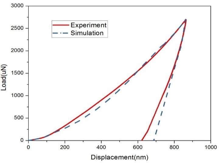
You can also read