The European MOB design platform for both Micro EVs and small M1 Vehicles - I-FEVS
←
→
Page content transcription
If your browser does not render page correctly, please read the page content below
Transport Research Arena 2014, Paris

           The European MOB design platform for both Micro EVs
                         and small M1 Vehicles
    L.Petruccellia*, V.Di Lagoa, S.Sandria, A.Pipinoa, C.Malvicinob, P.Guerrieric, P.Perlod,
                                     A.Lionettoe, G.Fontf
             a                              b                               c                 d
                 Centro Ricerche Fiat, Italy; Fiat Group Automobiles, Italy; Polimodel, Italy; IFEVS, Italy;
                                e                             f
                                  ST Microelectronics, Italy; IFP Energies Nouvelles, France

Abstract

This paper reports on the advancements on the MOB design platform launched on 2008 with the proposal P-
MOB evolved into the WIDE-MOB and EM-Safety projects of the EU Green Car Initiative. With a weight in
running mode below 600kg before the battery, the vehicle is the first of its kind that can address both the Micro
EVs world and with minor additions the conventional M1. The description regards: a novel structure adopted to
meet the highest Euro NCAP safety rating and long term structural stability - the design for an easy to implement
re-configurability for many uses and customer requirements - fail safe two motors configuration (effective four
wheel drives) - novel suspension systems specifically designed for the first in our knowledge “Born Electric”
supercar of the Micro EVs family - implementation of smart high efficiency conformable photovoltaic on
extended horizontal and vertical surfaces experimented up to an annual average 20km daily range in the Torino
area.

Keywords: Micro Electric Vehicles, multi-motor powertrain, smart photovoltaic, collision tests, vehicle
classification, system partitioning, EMF design criteria.

Résumé

Cet article rend compte des progrès sur la plate-forme de conception de MOB lancé en 2008 avec la proposition
PMOB impliquée dans les projets WIDE-MOB et EM-Safety de l'Initiative Green Car UE. Avec un poids en
mode de fonctionnement en dessous de 600 kg avec la batterie, le véhicule est le premier de son genre à pouvoir
traiter à la fois le type Micro EV et les ajouts mineurs la M1 classique. La description concerne: une nouvelle
structure adoptée pour répondre à la plus haute cote de sécurité Euro NCAP et de la stabilité structurelle à long
terme - la conception d'un outil facile à mettre en œuvre, re-configurable pour de nombreux usages et besoins
des clients – une configuration à deux moteurs en mode dégradé (quatre roues motrices) - de nouveaux systèmes
de suspension spécialement conçus pour la première fois à notre connaissance "Born Electric supercar" de la
famille Micro VE - la mise en œuvre de puce à haut rendement photovoltaïque sur des surfaces horizontales et
verticales expérimentée sur une moyenne annuelle de 20 journalier dans la région de Turin.

Mots-clés: véhicules micro-électriques, chaîne de traction multi-motorisée, photovoltaïque intelligent, essais de
chocs, classification de véhicules, partition des systèmes, crières de dimensionnement EMF

*Tel.: +39-011-9083855; fax: +39-011-9083083
E-mail address: luigi.petruccelli@crf.it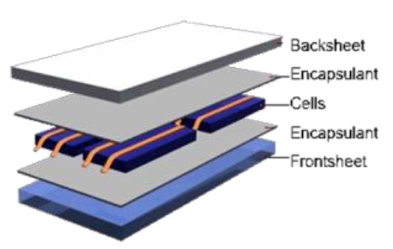
L. Petruccelli, P. Perlo/ Transport Research Arena 2014, Paris   2

1. Introduction

Electric vehicles are set to play a key role in the future of urban mobility, reducing pollution, decreasing
dependence on fossil fuels and saving drivers money. The demand for mobility is increasing in Europe as
elsewhere: several studies show that, mainly because of immigration from less developed countries; the linear
trend of EU traffic growth is expected to continue beyond 2020. Because the road network of several EU
Member States is at the limit of its capacity, rather than a growth of conventional vehicles sales, needs and
limitations will demand the integration different modalities and vehicles having a lower carbon footprint. Rather
than forms of mobility of ever increasing prices, there is a growing rational demand for: clean, safe and low
energy consumption vehicles, requiring less energy to be produced, and using recyclable materials-systems.

The business of Micro EVs has taken off in China as well as in Europe, they are gradually becoming a practical
transportation device confirming the emergence of ultra-low price vehicle, in fact the four wheels Micro EV
world is the fastest growing sector of electromobility with about 200,000 vehicles produced in China in 2013.
They do not require ABS-EPS systems and can be homologated by much simpler and quicker procedures than
those required by classical M1 vehicles. The design is typically reduced to the essential functionalities and no
stringent regulations have to be applied against crash and safety tests. In China and in many EU Countries these
vehicles can be driven by unlicensed people.
Personal mobility without restriction is by most intended as the first expression of freedom. In this direction the
size of the mean of transport matters; bikes and micro-cars allow degrees of freedom impossible with a large car.
The capacity to move goods or passengers around of small vehicle is far superior. The challenge addressed by
the wide mob platform is the design of safe, ergonomic and low footprint solutions that satisfy most people
needs and expectations in term of range, speed and price.
Starting from Europe the objective is to repeat with fully electric vehicles the success Kei Cars (thermal engines
L.Petruccelli, P. Perlo/ Transport Research Arena 2014, Paris

The classification should not be regarded as sharp as it could appear from table 1. Clearly vehicles cannot be
classified by weight only, their footprint and shape influence consume as well. LEVs as well as micro EVs are
very heterogeneous and could be subdivided into several subclasses. In some cases cars of 800-900kg are
classified as small while the category of large e-cars (ACEA executive) could be subdivided in two. The average
weight of US passenger cars is 480kg higher than the average weight of the EU ones and a car that in the US is
by most considered a micro car in Europe is classified within the lower-medium segment.
The macro classification per mass is the most useful to understand how technology evolution impacts
performance and production costs. Weight is usually correlated to size and aero drag influencing consume, range
and total capacity of the battery pack. Besides weight influences:
     • The DC link Voltage and the complexity of the battery system,
     • The rated power then heat dissipation in power electronic and motor(s) and the overall cooling system,
     • Semiconductor technology to be used (MOSFET/IGBT). Silicon is the basic material for LEVs,
          Micro, City and Small EVs while mid-size and large e-cars benefit of GaN, SiC components capable of
          handling much higher currents with better efficiency and heat dissipation property.
The global production of LEVs is approaching 50 millions units/year and in a logic of a step per step
implementation Micro cars and quad-cycles (here all together called Micro EVs) are stimulating the interests of
new producers and investors.
According to Regulation (EU) no 168 of 15 January 2013 “on the approval and market surveillance of two - or
three-wheels vehicles and quad-cycles”, heavy quad-cycles can be produced with a mass in running order ≤600
kg (vehicles intended for carrying goods not including the mass of batteries), and maximum net engine power up
to 15 kW. Including the battery pack the total weight of these vehicles could be > 700kg. The Mob platform
discussed in this paper is positioned in between the two quite different sectors of Micro EVs and M1 City e-cars.
The registration of a Micro EV can be made meeting few regulations and fast to implement processes, but in this
paper we demonstrate that with the addition of minimal hardware they can meet as well the burden of the
regulations necessary to enter the M1 world thus eliminating the restrictions on their use.

3. Design criteria

Aiming at a safe, ergonomic and efficient multipurpose fully electrical vehicle of low footprint, the basic
requirements set for the MOB platform are:
  • Micro EV type ( 30%, acceleration 0 – 50km/h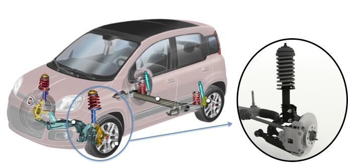
L. Petruccelli, P. Perlo/ Transport Research Arena 2014, Paris 4
4. Suspension systems and overall structural design
The starting point to meet the set criteria has been the adoption of the front corner wheels of the new Fiat Panda
for both the front and the rear axles figure 1. This choice assures robustness and reliability based on-road
experimentation of many billion kilometres as well as the access to low cost and large scale production
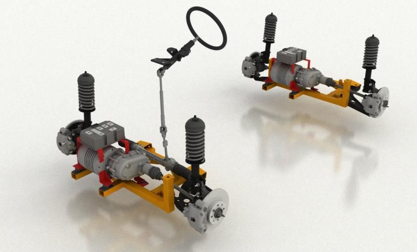
components. The coupling of the integrated block motor-differential- electronic drive into each axle is shown in
figure 2 where it can be noted that the two axles are a close replica of each other.
Fig. 1. Detail of the front corner wheel of the Fiat Panda based on a McPherson suspension system.
Fig. 2. Schematic view of the front and rear axles carrying-on the front corner wheel (shock absorber-hub-constant velocity
joint-lower suspension arm-braking system), semi-axis and steering box of the Panda coupled with the chosen integrated
block motor-differential-electronic drive; apart the steering box the rear axle is a close copy of the front axle.
Within the MOB platform a novel solution of fully autonomous and self-standing axles based on a parallelogram
suspension has been developed aiming at taking full advantage of electric propulsion. The developed concept is
shown on figure 3. With minimal changes on the elements of the PANDA corner, the McPherson architecture
can be transformed into a parallelogram scheme to be adopted in Micro e-supercars with higher:
• stability because of the lower centre of gravity,
• interior volume for carrying goods (and freedom in ergonomic design when carrying people) per the
same footprint because of the reduced height of the fixing points amongst the shock dampers and the
lower chassis.
Referring first to the more classical McPherson architecture, to assure easy entry for both the driver and rear
passengers we adopted a two door opening on the same side incorporating the B-pillar into the front door. Figure
3 shows the analysis performed to assure driver’s visibility according to the existing regulations-directives and a
picture of the first prototyped developed with on-board a driver and a passenger.
L.Petruccelli, P. Perlo/ Transport Research Arena 2014, Paris

Fig. 3. (a) Ergonomic study assuring a SAE 95 percentile driver’s visibility according to the existing regulations; (b) the first
                           developed prototype with on-board a “special” driver and a passenger.

For the upper and lower body structures (floor side walls, reinforcements, fenders, pillars and cross car beams)
we have designed and implemented two solutions aiming at:
1) Very large scale and low cost production based on “conventional” sheet metal forming,
2) Tubular frame with the addition of few parts only made by sheet metal forming conceived for low and
medium-low production volumes to reduce the invested capital as shown in figure 4.

    Fig. 4. The implemented tubular frame with the addition of parts made by sheet metal forming conceived for low and
                                            medium-low production volumes.

With both approaches the simulated crash tests prove that the adopted structures can meet the requirements of
regulations ECE-R94 (frontal collision safety), and ECE-R95 (occupant protection in lateral collisions), the two
most directly related to Euro NCAP tests in terms of specification, driver dummy and injury criteria.
Besides, because the MOB vehicle has only one central seat in the front the simulations and the experimentation
have also been performed following the regulation ECE-R12 (steering mechanisms impact in frontal collision)
per which the unladed vehicle, in running order, without a manikin, is collision-tested against a rigid barrier at a
speed of 48.3-53-1 km/h (figure 5 and figure 6).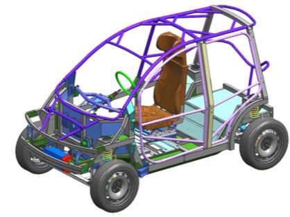
L. Petruccelli, P. Perlo/ Transport Research Arena 2014, Paris   6

Fig. 5. Tubular frame with the addition of parts made by sheet metal forming. ECE-R12: Steering deformation. The top of the
steering column and its shaft move backwards, horizontally and parallel to the longitudinal axis of the vehicle well below the
 12.7 cm threshold set by the regulation and also less than 12.7 cm vertically upwards in relation to a point of the vehicle not
                                                    affected by the impact.

   Fig. 6. Tubular frame with the addition of parts made by sheet metal forming. ECE-R12: Decelerations in nodal points.

In terms of lateral collision the simulations have been performed following the regulation ECE-R95 per which
the vehicle is stationary and a mobile deformable barrier of 950 kg is moving perpendicular to longitudinal
median vertical plane of the vehicle at a speed of 50 ± 1 km/h and coincident within ± 25 mm with a transverse
vertical plane passing through the R point of the front seat adjacent to the struck side of the tested vehicle at the
moment of the impact and within two planes determined before the test and situated 25 mm above and below the
previously defined plane. The plastic strain analysis demonstrates that structural integrity and ruptures, resulting
from permanent deformation, are quite acceptable with no risks to increase injury. The deceleration induced on
the four nodal points (as well as the seat) can be quite high proving that the structural design of a L7e vehicle
meeting the criteria of the PMOB platform should made such that: 1) the weight of the vehicle is kept as close
(high) as possible to the limit of the regulation (600kg before battery) 2) it adopts seats incorporating side impact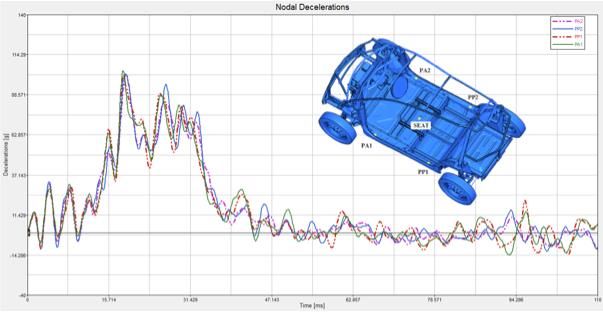
L.Petruccelli, P. Perlo/ Transport Research Arena 2014, Paris

airbags 3) the structure against lateral crash is the result of the compromise between an acceptable level of lateral
deformation aiming at a lower nodal deceleration.
In summary within the MOB platform we have proved that the structure of Micro EVs weighting less than 600kg
before the battery, when properly equipped with airbags and safety belts, can meet the UN-ECE regulations in
place and be potentially awarded the highest Euro NCAP ratings.

5. Powertrain

Since its launch the MOB platform has been conceived in a two motor architecture for the following reasons:
•    Fail-safe,
•    Effective four wheel drive,
•    Higher efficiency than when adopting a single motor,
•    Adaptable torque control over two fully independent axles,
•    High vehicle stability in bad weather conditions and in low radius curves,
•    Allows higher real and “perceived” accelerations,
•    Partition of the power with lower currents and voltages allowing: thermal management with air cooling
     only, lower stress on batteries, lower complexity on battery serial connections,
•    Reduced EMF impacts because of the lower currents and voltages without a compromise on efficiency,
•    Better weight distribution over the two axles,
•    High flexibility for future autonomous drive (easy to implement four steering wheel concepts),
•    Allows an easier implementation of functions emulating and complementing the mandatory ones such as
     ABS and ESC physically implemented in conventional motorizations,
•    Allows lower cost and easy to access power electronic drives based on MOSFETS.

 Although the tests performed proved that a 2x5kW motors configuration could satisfy the original specifications
 set for the MOB platform for the final powertrain we have considered motors with higher powers in three
 different motor-transmission configurations:
• 2x7kW PMSM motors in a single gear ratio 1:4.5 (as per the configuration described in figure 2),
• 2x7kW PMaSyRM permanent magnet (ferrite) assisted synchronous reluctance machine in a single gear ratio
     of 1:7.8,
• 2x7kW PMSM (PMaSyRM) motors coupled to an automatic two ratios gear-box gear as per the schematic
     configuration reported in figure 7 (aiming at higher global efficiency, reducing the acceleration time 0 –
     50km/h and reducing current loads while increasing speed at high percentile slopes).

  Fig. 7. Schematic representation of the two motors powertrain implemented with a two ratios gear-box transmission system
     and a single battery pack. For all new implementations of the MOB platform the charger is allocated off-board and in
                                           bidirectional link with the BMS via CAN.

The DC link operates at a nominal voltage of 120V, a value selected as a compromise resulting from a multi-
parameter complex figure of merit including: battery, motor drive, motor and transmission ratio of the
differential, overall cost, safety, technology availability and overall robustness. Usually the efficiency of the
L. Petruccelli, P. Perlo/ Transport Research Arena 2014, Paris   8

motor is only minimally dependent from the driving voltage; at 120V and at peak powers of the order of 14kW
the current losses in the winding are still acceptable while at nominal voltages lower than 90V much higher
currents would be needed inducing critical losses on both drives and motors. At 120V the technology is now
offering efficient, robust and low cost MOSFETs drives that can withstand currents up to 450A, about three
times the peak current requested for both selected motor technologies to generate a peak torque of 55Nm.

The collaboration of the MOB platform with the EM-safety project has led to the setting of basic design criteria
for the powertrain that can be synthetized in the following points:

Batteries
•    Since a battery pack consists of either or both a parallel and serial connection of sub-modules, currents in
     the sub-modules and in the interconnectors may become a significant source for EMF emission. The battery
     compartment and the passenger seat area should always be separated by a bilayer steel-plastic shield.
•    The cables connecting battery cells and submodules should not form a loop, and where possible, the
     interconnectors for the positive polarity should be as close as possible to those of the negative polarity.
Cables
•    To minimize EMF emission DC cable carrying significant amount of current, should preferably be made in
     the form of a twisted pair so that the currents in the pair always flow in the opposite directions.
•    For three-phase AC cables, three wires should be twisted and made as close as possible so as to minimise
     its EMF emission.
•    All power cables should be located at least 100mm away from metallic parts of the lower and higher
     chassis structure,
•    All power cables should be positioned as far away as possible from the passenger seat area, their layout
     should not form a loop and some forms of shielding is always preferred,
•    A thin layer of ferromagnetic shield is recommended as this is cost-effective solution for the reduction of
     EMF emission as well EMI emission,
•    Where possible, power cables should be separated from the passenger seat area by a steel sheet.
Motors
•    Where possible, the motor rotation axis should not point to the seat region.
•    Motors and passenger seat area should be separated by a steel sheet.
•    Motor housing should be electrically well connected to the vehicle metallic chassis to minimise any
     electrical potential.
•    Drive and motor should be mounted as close as possible to each other to minimise the cable length.
A visualization of the first developed vehicle with a two motors powertrain is shown in figure 8.

       Fig. 8. Picture of the first MOB vehicle and a transparency showing the position of motors and battery pack.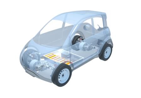
L.Petruccelli, P. Perlo/ Transport Research Arena 2014, Paris
6. Solar Energy harvesting
The application of photovoltaic panels on-board road vehicles has become particularly attractive because of the
availability:
• Low cost Si mono-crystalline cells with efficiency > 23%,
• Long life, scratch and heat resistance highly transparent flexible techno-polymeric sheets,
• High efficiency and low cost by pass “cold-diodes” that allow to minimize the impact of partial shadowing,
single cell rupture, localized dust and spots.
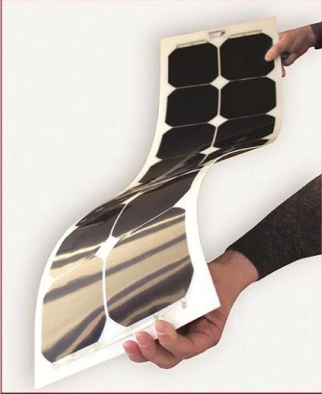
Flexible and robust panels having efficiency of the order of 21% with co-laminated “cold” by pass diodes are
currently priced in the range of 1.3-1.5€/W thus opening a new low cost perspective in road vehicles for which a
typical 300W (2.2m2) panel composition can be installed at a cost of 600-650€. The technology used in the MOB
platform is based on SolbianFlex panel composed of backcontact SunPower Corporation Si mono-crystalline 5
inches cells laminated in a final flexible 5 layer polymeric sandwich as shown in figure 9.
Fig. 9. The technology meets certification IEC 61215 Ed 2 and IEC 61730 thus passing very strict aging and resistance tests
ensuring modules lifetime of at least 20 years.
The installations in the MOB platform consists of five sub-modules: two on the roof, two on the rear side
windows and one sliding behind the windshield activated by the conventional wireless key used to close and
open the doors, it slides down when the doors are locked from the outside and slides up when the driver enters
into the vehicle. The partition combined with the use of SPV1001 STmicroelectronics by-pass cold diodes is
chosen to minimise the impact of partial shadowing as well as to facilitate the installations in that each module is
managed independently from the other. A single electronic board is equipped with a stage of five independent
maximum power point tracker (MPPT) electronic lines searching the point at which each solar panel current and
voltage produces the maximum power, the second stage of the board consists of a dc-dc converter directly
connected to the high voltage battery pack (120V nominal) and adapting its output in relation to the state of
charge. The BMS is linked via CAN to the PV control board and manages charging like any other external
charging systems. The BMS monitors PV energy every minutes and the average value stored can be visualized
directly on the on-board display or a cellular phone. An example of the energy stored in the battery pack is
reported on table 2.
Tab. 2. Torino 12th July, 2012: The accumulated PV energy in the li-ion battery pack all over 11 hours was 1600Wh.
L. Petruccelli, P. Perlo/ Transport Research Arena 2014, Paris   10

With about 1.9m2 of effective working area and 20.5% efficiency, the output of the panels is in line with the
expectation derived from the JRC Photovoltaic Geographical Information System. With 50% energy recovery
during deceleration and braking the MOB vehicle requires an average of about 75Wh/km to cover the NEDC
cycle; this demonstrates that an average 20km/day run by solar radiation only is feasible adopting on-vehicle
robust and affordable smart photovoltaic. The MOB platform has then opened a perspective per which in most
EU southern countries most trips can be run with Micro EVs by solar radiation only.

7. Conclusions

The micro EVs world is new and very little background material is available because neither the old EU
regulation nor the new 168/2013 on L7e demand crash tests or homologations applying the UN-ECE or Euro
NCAP ratings adopted for M1 vehicles.
The MOB platform has generated knowledge and solutions demonstrating that vehicles weighting less than
600kg before the battery can:
    • Comply with the most stringent safety regulations applied for M1 vehicles on redundancy (fail safe),
         vehicle control stability, frontal and lateral collisions,
    • Be designed with performance (range, speed, acceleration and fun to drive) that can satisfy most people
         needs in terms of passenger vehicles, delivery of goods or leisure-sports,
    • Be equipped with smart solar panels that can harvest energy sufficient to avoid charging many days of
         the year in most EU southern countries.
With that the MOB platform is setting EU commercial standards in quality, safety and performance against
which non-EU manufacturers have to be faced in the next years.

Acknowledgements
The authors greatly acknowledge the coordinated financial support of DG-RTD and DG-CONNECT of the
European Commission via the collaborative projects WIDE-MOB (266129) and P-MOB (260087).

References
http://www.evworld.com/news.cfm?newsid=30732

http://www.greencarreports.com/news/1084678_kei-cars-japans-tiny-but-often-high-tech-minicars

www.acea.be and http://www.ihs.com/info/ev/automotive-conference-series/index.aspx

“89% of EV owners in California report using their EVs as their primary car”, report published by the California
Center for Sustainable Energy (CCSE), July 2012 available at www.energycenter.org

According to the ACEA the current EU conventional sales consists of 70% of vehicles weighting between 750-
1370kg (small and lower-medium vehicles) with a market trend towards lower segments. EU Economic report
2011, www.acea.be

Regulation (EU) no 168/2013 of the European Parliament and of the Council of 15 January 2013 on the approval
and market surveillance of two- or three-wheel vehicles and quadricycles.

New tax scheme reduces emissions from vehicles, July 19, 2012, Norwegian School of Economics,
http://sciencenordic.com/new-tax-scheme-reduces-emissions-vehicles

M. Grunig et al, An overview of Electric Vehicles on the market and in development, Report, Delft April 2011.
Reporting an extensive analysis per weight.

www.solbian.eu

http://re.jrc.ec.europa.eu/pvgis/
You can also read