The field guide to 3D printing in microscopy - Preprints.org
←
→
Page content transcription
If your browser does not render page correctly, please read the page content below
Preprints (www.preprints.org) | NOT PEER-REVIEWED | Posted: 14 May 2021                                                  doi:10.20944/preprints202105.0352.v1

              The field guide to 3D printing in microscopy
                    Mario Del Rosario1,* , Hannah S. Heil1,* , Afonso Mendes1,* , Vittorio Saggiomo2 , and Ricardo Henriques1,3

                                                            1
                                                              Optical Cell Biology, Instituto Gulbenkian de Ciência, Oeiras, Portugal
                                        2
                                           Laboratory of BioNanoTechnology, Wageningen University and Research, Wageningen, The Netherlands
                        3
                          Quantitative Imaging and Nanobiophysics, MRC Laboratory for Molecular Cell Biology, University College London, London, United Kingdom
                                                                             *
                                                                               These authors have contributed equally

         The maker movement has reached the optics labs, empower-
         ing researchers to actively create and modify microscope de-
         signs and imaging accessories. 3D printing has especially had
         a disruptive impact on the field, as it entails an accessible new
         approach in fabrication technologies, namely additive manufac-
         turing, making prototyping in the lab available at low cost. Ex-
         amples of this trend are taking advantage of the easy availabil-
         ity of 3D printing technology. For example, inexpensive micro-
         scopes for education have been designed, such as the FlyPi (1).
         Also, the highly complex robotic microscope OpenFlexure (2)
         represents a clear desire for the democratisation of this tech-
         nology. 3D printing facilitates new and powerful approaches to
         science and promotes collaboration between researchers, as 3D
         designs are easily shared. This holds the unique possibility to
         extend the open-access concept from knowledge to technology,
         allowing researchers from everywhere to use and extend model
         structures. Here we present a review of additive manufacturing
         applications in microscopy, guiding the user through this new
         and exciting technology and providing a starting point to any-
         one willing to employ this versatile and powerful new tool.
         3d printing | microscopy | open-source | optics | super-resolution
         Correspondence: rjhenriques@igc.gulbenkian.pt

         Introduction
         From the first microscopes invented in the late 16th century
         to the most recent iterations that can resolve targets beyond
         the diffraction limit of light, microscopy-based approaches
         represent a critical tool to study biological phenomena (3).
         Recent years have seen a sharp increase in bespoke micro-
         scopes, achieving excellent results where commercial solu-
         tions were ineffective, for example the the Warwick Open
         Source Microscope (WOSM) (https://wosmic.org) and the
         OMX Microscope (4). However, researchers are often lim-
         ited to commercial parts, as fabrication methods to reliably
         manufacture microscope components are expensive and slow.
         This limitation hampers the diversity of new designs, ulti-
         mately restricting the innovation of new technology.
         The approach of 3D printing holds great potential in this re-
         gard as it has had a disruptive impact on the field of manufac-                      Fig. 1. 3D printing process: from concept to reality. 3D printing starts with an
         turing. This impact is based on its rapid prototyping approach                       idea or a necessity to produce a specific object. A digital 3D model can be made
                                                                                              “from scratch” or downloaded from an online database. The file encoding the 3D
         to the creation of physical objects, called additive manufac-                        model needs to be processed in a slicing software, which divides the model into
         turing. Additive manufacturing has seen a massive rise in                            layers and creates instructions that the 3D printer can interpret. Depending on
         popularity in recent years, from its start as an industrial proto-                   the desired results, different 3D printing technologies can be employed, which use
                                                                                              different base materials (e.g. SLA uses resins and produces better details; FDM
         typing tool to the current domestic use. It is employed across                       uses polymer filaments and produces high mechanical resistant products). Once
         many different settings, from the user printing miniature fig-                       the product is printed it might require further processing to achieve a high-quality
         urines using common polymers in a small domestic printer                             finish (e.g. smooth surfaces).
         (5) to entire houses using concrete in huge industrial ma-
         chines (6). In 3D printing, a structure is built bottom-up in an

                                                                                                                      Del Rosario, Heil & Mendes et al.   |   May 25, 2021   |   1
             © 2021 by the author(s). Distributed under a Creative Commons CC BY license.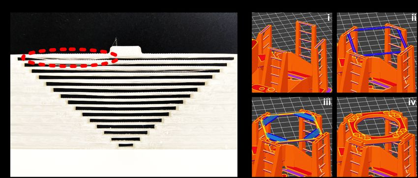
Preprints (www.preprints.org) | NOT PEER-REVIEWED | Posted: 14 May 2021                           doi:10.20944/preprints202105.0352.v1

          additive manner by depositing sub-mm layers of material. In         software, which divides the object in layers and calculates
          contrast, conventional manufacturing processes usually rely         the path that the printer needs to travel to produce them. The
          on manual labour and automated processes such as casting,           “slicing” software can also be commercial or open-access
          forming, and machining by either subtracting material from          (see also "Box 1. Software tools" below).
          a larger starting piece or using moulds to shape an object (7).     Once a g-code file is created, the next step is 3D printing. The
          The additive manufacturing approach pursued in 3D printing          selection of materials and 3D printing technology will de-
          uses simplified one-step manufacturing processes, reducing          pend on various factors including cost, speed, material char-
          material waste, which in subtractive fabrication methods such       acteristics and needs. This review’s scope is limited to com-
          as milling can be as high as 90% (8).                               mercial and common 3D printers, which use filaments and
          In scientific research, additive manufacturing is rapidly be-       liquid resins to print with FDM and (m)SLA, respectively.
          coming a critical tool allowing the rapid development of new        Moreover, other printing technologies use different materi-
          designs and the prototyping of machine components with an           als, including metals, ceramics, concrete, and even food (10).
          unprecedented speed. These components can be assembled to           Depending on the machine used and the printing job, the
          create complex machinery such as microscopes (2). Besides           printing process can be lengthy, taking over 1 day in some
          the advantage of rapid manufacturing, 3D printing facilitates       instances to complete. Once the object is printed, it can be
          novel and powerful approaches to solving problems in sci-           subjected to post-processing steps.
          ence, as it provides ample room for creativity. Additionally,
          3D printing communities are well established, promoting col-            Box 1. Software tools: for 3D design:
          laborations between researchers and even the general public,
          as 3D designs are easily shared. 3D printing holds the unique           3D design software tools
          possibility to extend the open-access concept from knowl-
          edge to technology, allowing researchers and people with a              TinkerCAD: free, creation and rendering of
          keen interest in science to use, iterate designs and adapt ex-          3D models, tutorials and teaching resources, inter-
          isting ones for different projects with a high degree of cus-           active modeler and script based, very accessible
          tomisation.                                                             even for unexperienced users, browser based
                                                                                  (www.tinkercad.com)
          What is 3D printing?                                                    OpenSCAD: Free, creation and rendering of 3D
                                                                                  models, only script based. It might not be that intu-
          3D printing is a process that creates a physical object by
                                                                                  itive to start with, but the short and comprehensible
          adding layers of material to recreate a 3D digital object.
                                                                                  list of commands summarized on the cheatsheet is a
          Fig. 1 shows the typical framework used in 3D printing. This
                                                                                  great help. (www.openscad.org)
          technology involves three main steps: the digital design of
                                                                                  FreeCAD: free, creation and rendering, modeler
          a 3D object, the computation of the printing instructions re-
                                                                                  based (www.freecadweb.org)
          quired by the printer and, finally, the fabrication of said ob-
                                                                                  Blender: free, 3D model creation, rendering and
          ject by adding patterned layers of new material. Depending
                                                                                  animation
          on the application, vastly different 3D printing technologies
                                                                                  Fusion360:        commercial software tool with
          that use different materials can be employed. This review fo-
                                                                                  free non-commercial subscription for one year
          cuses on two of the most popular methods: Fused Deposition
                                                                                  (www.autodesk.com/products/fusion-360)
          Modelling (FDM) and Stereolithography (SLA). The print-
                                                                                  Rhino3D: commercial, free-form 3D modeling,
          ing process itself is as simple as melting plastic filaments in
                                                                                  creation, rendering and animation, handels complex
          an extruder and using them to form layers that create me-
                                                                                  models and point clouds (https://www.rhino3d.com)
          chanically strong objects (as done in FDM), or using light to
                                                                                  3DS Max: commercial, 3D model creation, render-
          selectively polymerise resins step by step to obtain highly in-
                                                                                  ing and animation (www.autodesk.com/products/
          tricate and complex forms (as done in SLA) or masked SLA
                                                                                  3ds-max)
          (mSLA) (9).
                                                                                  SolidWorks: commercial, 3D model creation and
          Additive manufacturing starts with a 3D model designed
                                                                                  rendering, includes motion and stress analysis tools.
          from scratch or downloaded from the internet (Fig. 1). This
                                                                                  (www.solidworks.com)
          is an exciting aspect of the technology, as files can be easily
          shared online, greatly increasing accessibility. The files are
          created and visualised in commercial or open-access 3D soft-            Free software tools for G-code creation
          ware (see also "Box 1. Software tools"). Once the 3D model
          is ready, it needs to be converted into a “.STL” file, which            •   Slic3r: FDM (www.slic3r.org)
          stands for Standard Tessellation Language. This is usually              •   PrusaSlicer: FDM (www.prusa3d.com)
          done by the CAD-type software itself but requires additional            •   ideaMaker: FDM (www.ideamaker.io)
          steps if using non-CAD based software. Once the .STL file               •   Ultimaker Cura: FDM (https://ultimaker.com)
          is obtained, the printing pattern or path needs to be converted         •   PreForm: SLA (https://formlabs.com)
          into a set of instructions that a 3D printer can interpret (i.e.,       •   chitubox: mSLA (https://www.chitubox.com)
          for FDM, a "g-code"). This step is performed by a "slicer"

          2   |                                                                             Del Rosario, Heil & Mendes et al.   |   3D printing in microscopy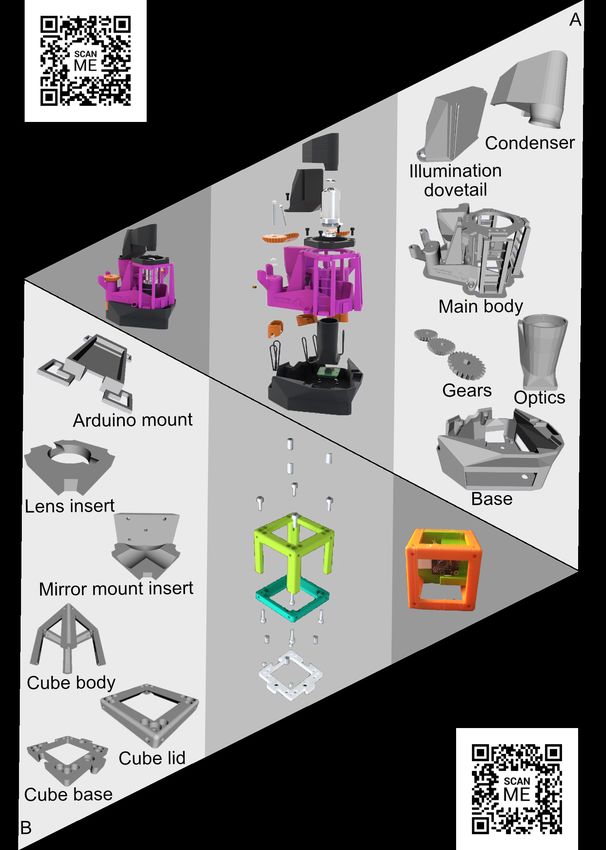
Preprints (www.preprints.org) | NOT PEER-REVIEWED | Posted: 14 May 2021                                                 doi:10.20944/preprints202105.0352.v1

                                                                                                   the capability to design and fabricate scientific instruments,
                                                                                                   reducing fabrication time, cost, and structural limitations.
                                                                                                   More importantly, low-cost and highly sophisticated research
                                                                                                   tools are now accessible to a wider range of researchers, al-
                                                                                                   lowing a worldwide audience to benefit from better technol-
                                                                                                   ogy without relying on commercial solutions. 3D printing
                                                                                                   also facilitates iterative design-based approaches that would
                                                                                                   be difficult, if not impossible otherwise. Additionally, these
                                                                                                   benefits are available to the general public as well, as com-
                                                                                                   mercial 3D printers are now more accessible than ever. This
                                                                                                   aspect is particularly important because it enables “citizen
                                                                                                   scientists”, empowering existing research avenues by in-
                                                                                                   creasing research output via crowd sourcing, which benefits
                                                                                                   society.
                                                                                                   Many examples of this trend are taking advantage of the easy
                                                                                                   accessibility of 3D printing technology (see also Movie S1).
                                                                                                   For example, inexpensive microscopes for education are be-
                                                                                                   ing produced, such as the FlyPi (1). Also, the highly complex
                                                                                                   robotic microscope OpenFlexure (3) represents a clear desire
                                                                                                   to democratise this technology. On the other hand, additive
                                                                                                   manufacturing is rapidly becoming the tool of choice in mi-
         Fig. 2. Mindmap showing printed parts for microscopy applications. Additive man-
         ufacturing is currently used in many open source projects in microscope modular
                                                                                                   croscopy technology development, as 3D printing technol-
         designs. With the exception of a few parts, it is currently possible to print whole mi-   ogy such as FDM allows rapid prototyping with an unprece-
         croscope bodies at relatively low prices. Additionally, 3D printing is used for sample    dented level of freedom. This freedom in design paired with
         control such as microfluidics systems and sample holders.
                                                                                                   the unmatched speed in the generation of prototype com-
                                                                                                   ponents creates a perfect combination for innovating new
         For example, including support structures in the model is of-                             cutting-edge technology where highly complex components
         ten required to print difficult areas (e.g., bridges and over-                            can be fabricated and iterated upon with relative ease (Fig. 2).
         hangs); these need to be removed manually afterwards, or                                  These characteristics enable systems such as miCube (13),
         dissolved in water if water-soluble filament is used (e.g.                                the UC2 (14), and the the Warwick Open Source Microscope
         polyvinyl alcohol). Moreover, some models are printed in                                  (WOSM) (https://wosmic.org), where further customisation
         pieces that need to be assembled in an extra step. Finally,                               is possible due to their modular design. The microscope parts
         high-level surface finishes can be achieved by sanding, weld-                             that can be built vary with the technology and materials avail-
         ing with organic solvents, painting, and polishing.                                       able. In the literature, whole microscope bodies have been
                                                                                                   printed, including the base (13, 15), the body (13, 15, 16),
         3D printing in microscopy                                                                 holders for the filters (15, 17), objectives (18), coverslips
                                                                                                   (14), pinholes (14, 16) and heat sinks (18). Additionally, mi-
         With regard to the field of microscopy, 3D printing technolo-                             croscope chambers (19) and controller mounts (20) have also
         gies are creating an impact in two critical aspects: accessi-                             been implemented, allowing a high degree of customisation
         bility and rapid prototyping of customised equipment. Along                               to researchers that adopt this technology.
         the lines of “Seeing is believing”, microscopy plays a crucial                            3D printing is also used to print tools that allow for more
         role in studying biological processes by providing informa-                               complex microscopy solutions. Sample manipulation is an
         tion far beyond the details perceived by the naked eye, down                              important aspect of this process that includes sample hold-
         to the level of molecular organisation. From the very early                               ers, sample surveying, and microfluidics systems (see also
         days where Antonie van Leeuwenhoek observed protists and                                  Movie S2). Sample holders are in direct contact with the
         bacteria for the first time (11), to the modern super-resolution                          sample, requiring biocompatible materials that are readily
         solutions capable of resolving images below the light diffrac-                            available or made biocompatible by post-processing. Exam-
         tion limit (∼ 300 nm), microscopy is the backbone of biology                              ples include cell grid holders (21) and incubation chambers
         research (12).                                                                            (22). Sample surveying using Atomic Force Microscopy can-
         Microscopy technology today is currently still limited in its                             tilevers has also been 3D printed (23). Microfluidics can
         application, often requiring high investment and specialised                              be used to control the movement of small liquid and parti-
         training. This puts researchers with limited funds at a disad-                            cle volumes in a network of interconnected microchannels.
         vantage, granting access to sophisticated imaging approaches                              Microfluidics is useful to dispense, mix, separate, and de-
         only to researchers from wealthy countries and facilities.                                tect different reagents into a sample, allowing a high de-
         This has given rise to a new movement in microfabrication                                 gree of manipulation using a system of automatic miniature
         and microscopy to create open access and inexpensive tech-                                pumps and Lab-on-Chip devices. Additionally, pump sys-
         nology that can be accessible to a wider audience. In re-                                 tems have been fully automatised to allow sample manipula-
         cent years, 3D printing-based solutions drastically increased

         Del Rosario, Heil & Mendes et al.    |   3D printing in microscopy                                                                                    |   3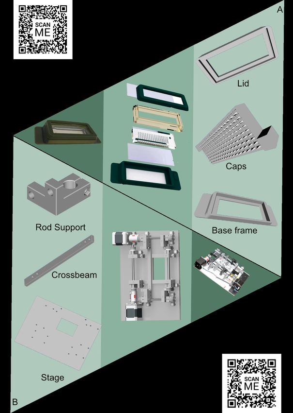
Preprints (www.preprints.org) | NOT PEER-REVIEWED | Posted: 14 May 2021                        doi:10.20944/preprints202105.0352.v1

          tion for downstream microscopy applications such as fixation     This practice can be particularly useful in fieldwork where
          and immunofluorescence (24, 25).                                 conditions are not ideal for laboratory equipment. Projects
                                                                           such as cellSTORM have shown that it is possible to achieve
          3D printed microscopy projects                                   SMLM using consumer mobile phones and achieve optical
                                                                           resolutions higher than 80 nm. The project also benefits from
          Microscopes are usually highly intricate machines composed       using a trained image-to-image generative adversarial net-
          of a multitude of parts with varying degrees of complex-         work (GAN) to reconstruct video sequences under subopti-
          ity. These parts have been traditionally built using standard    mal conditions, improving signal-to-noise ratio by compen-
          micro- and macro- fabrication methods that are expensive         sating noise and compression artefacts (31). As the high per-
          and, in some cases, restrictive. The implementation of 3D        formance scientific camera is usually one of the most expen-
          printing approaches in the rapid fabrication and prototyping     sive components of a microscope, exchanging it for a mobile
          of optomechanical components allows the creation of new          phone camera allows to significantly reduce the overall costs
          microscopy approaches, particularly when the designs incor-      of the system, even more so by integrating this approach into
          porate methods to sense, process, and act automatically via      a 3D-printed microscope. This approach has been pursued
          computer-based controllers such as Arduino or Raspberry Pi.      for the FPscope project, capable of high-resolution imaging
          Using additive manufacturing to produce specific microscope      using variably illuminated, low-resolution intensity images
          components is highly beneficial, allowing fine-tuning to suit    in Fourier space, called Fourier ptychographic microscopy.
          specific design requirements. It has been reported that 3D       Here, the mobile phone lens is used in a reversed manner
          printing can reduce a microscope parts’ price between 50%        where the mobile phone lens projects the magnified image to
          and 90%, depending on the component (26). The perfor-            the detector (32). The µSmartScope is another example of
          mance of the 3D printed parts (kinematic mounts, transla-        a 3D printing adaptor that can be fitted into a wide range of
          tion stages, and integrating spheres) were directly compared     mobile smartphones. In addition, the motorised stage is fully
          to commercial counterparts to assess their precision perfor-     automated and controllable by the smartphone and is capable
          mance. One of the tradeoffs that has to be accepted is the       of autonomous image acquisition (33).
          printed part’s limited physical integrity, which can be com-
          pared to low-end commercial alternatives (26). Nevertheless,     Especially for particular tasks where the limited camera per-
          smartly designed and highly tailored components such as a        formance and computation power is sufficient, smartphones
          monolithic 3D printed flexure translation stage have been re-    are used for microscopy applications in enabling point-of-
          alized with this approach. This stage was capable of sub-        care and field diagnostics. These kinds of applications are
          micron-scale motion with remarkably low drift and minimal        for example DNA fluorescence spectroscopy for the read-
          post-processing (27). Micromanipulators and probe position       out of fluorescence-based biological assays to detect spe-
          systems have also been 3D printed and tested using flexible      cific nucleic acid sequences reached the point of detecting
          materials with substantial price reductions when compared to     single-base mutations (34). Other DNA-based applications
          commercial options (28). Even tunable objectives have even       include a surface-heated droplet PCR system to detect Es-
          been realized by aligning customised poly (methyl methacry-      cherichia coli that employs wire-guided droplet manipula-
          late) (PMMA) singlets and a miniaturized electrowetted lense     tion to guide a droplet over three different heating cham-
          for electronic focusing within a 3D-printed housing (29).        bers. Following product amplification, end-point detection
          While the fabrication of optically active elements usually re-   is achieved using the smartphone-based fluorescence micro-
          quires nanoscale precision far beyond the capability of the      scope (35). Automated cell identification has also been done
          3D-printing techniques featured in this review, the imple-       using a 3D printed shearing digital holographic microscope
          mentation of near-refractive index matched media allows to       for fieldwork. It uses a common path shearing interferom-
          realize a phasemask based on a 3D-printed mould with mi-         eter for automatic cell identification via a CMOS or a mo-
          crometer topography (30). Beyond this, low cost, compact         bile phone camera and the addition of laser illumination and
          and high-performance illumination systems have been real-        a commercial objective (36). Another holographic lens-less
          ized employing 3D printed components, such as the Nico-          smartphone-based microscope has been designed for holo-
          Lase project. NicoLase is an open-source diode laser com-        graphic micro-object imaging of a variety of samples using
          biner, fiber launch, and illumination sequence controller for    a CMOS camera chip and controlled by a Raspberry Pi (16).
          fluorescent microscopy and super-resolution applications that    Further examples of smartphone-based projects differentiate
          successfully competes with the performance of commercial         between white blood cells with acridine orange staining using
          systems at half of the costs (20).                               a miniature achromatic microscope (37), identify pathogenic
          The increase in mobile phone usage backed by powerful cam-       bacteria using a DNA-based FISH assay (38), and image and
          eras and increasing computational output has given rise to       identify malaria parasites with a ball lens objective capable of
          the field of mobile microscopy. Although not as power-           high-resolution bright field imaging of Plasmodium parasites
          ful as high-end dedicated cameras, it is still possible to use   in blood smears for field diagnostics (39).
          cellphone cameras to capture microscopy data after adapting      Perhaps the most interesting application of 3D printing in mi-
          hardware and software for this purpose. Mobile smartphones       croscopy is the generation of fully functioning microscopes
          have achieved enough computational power that both acquisi-      with few non-3D printed components. 3D printed micro-
          tion and processing is now possible in the same device (31).     scopes pose an exciting concept that combines iterative and

          4   |                                                                          Del Rosario, Heil & Mendes et al.   |   3D printing in microscopy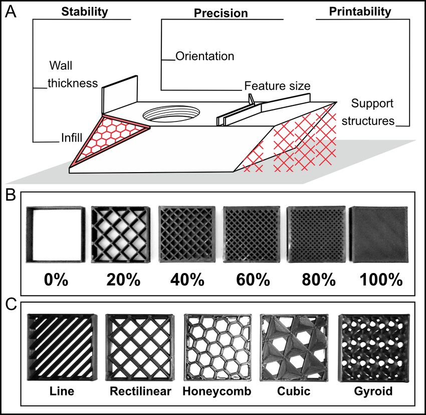
Preprints (www.preprints.org) | NOT PEER-REVIEWED | Posted: 14 May 2021                                             doi:10.20944/preprints202105.0352.v1

                                                                                               ure microscope is controlled using the OpenFlexure software
                                                                                               stack that is both cross-platform and language-independent.
                                                                                               Control is split between a client and a server application that
                                                                                               interface with each other using a web API with the W3C Web
                                                                                               of Things standard. This characteristic provides a modern
                                                                                               interface, multi-language support, minimizes code duplica-
                                                                                               tion, allows multiple microscopes to be controlled by a sin-
                                                                                               gle computer, and integrates research experiments, users, and
                                                                                               equipment (43). The OpenFlexure project was co-developed
                                                                                               between the University of Bath and the Tanzanian company
                                                                                               STICLab. Co-development of a project such as this shows
                                                                                               the potential of open-source 3D printing projects where ge-
                                                                                               ographical boundaries no longer limit scientists from low-
                                                                                               income countries to access better resources, improving their
                                                                                               research freedom (2). The OpenFlexure project has also been
                                                                                               combined with SRRF (44) for super-resolution applications
                                                                                               (45).
                                                                                               Another example of a 3D printed microscope with super-
                                                                                               resolution capacity is the Chea(i)p, a self-contained super-
                                                                                               resolution microscope that uses a commercial objective and a
                                                                                               mobile phone, and costs less than C800. In this case, the mo-
                                                                                               bile phone does the acquisition, processing, hardware con-
                                                                                               trol, and photonic-chip illumination. Impressively, it can
                                                                                               reach resolutions of 100 nm with SMLM and live super-
                                                                                               resolution with SRRF (46). Furthermore, the waveguide-
                                                                                               PAINT system allows a highly uniform 100 × 2000 µm2
                                                                                               area evanescent field for TIRF illumination. The system
                                                                                               was developed as a stable, low-cost microscope with a 3D-
                                                                                               printable chip holder to facilitate alignment and imaging. The
         Fig. 3. 3D printed microscope parts. Microscope individual parts can be 3D printed
                                                                                               waveguide-PAINT is capable of imaging multiple whole cells
         and following post-processing, can be assembled to create a fully working micro-
         scope. (a) The OpenFlexure Microscope is an example of an almost fully 3D-            or whole origami structures such as microtubules in COS-7
         printable microscope (3). (b) The UC2 project (40) is based on cubic structures       cells in a single field of view (47).
         able to integrate inserts to allow microscopy techniques such as SIM. Certain parts
         can not be 3D printed and are sourced independently (e.g. lenses and electronics).    3D printing has also been adapted to Selective Plane Illumi-
                                                                                               nation Microscopy (SPIM). SPIM, also known as light-sheet
         collaborative design, resulting in highly customisable equip-                         microscopy, is extremely useful for volumetric imaging of
         ment that would be very expensive to obtain using other fab-                          large samples as optical sectioning is achieved by employ-
         rication methods. Thus, beyond the iterative design aspect,                           ing a sheet of light as illumination. The OpenSPIM project
         many 3D printed microscopes are open-source projects that                             is an open-access platform that allows new users to build a
         present a unique opportunity to provide accessibility to novel                        basic SPIM microscope step-by-step (18). Beyond applica-
         ground-breaking designs to a wide range of researchers by-                            tions in education and scientific outreach (48), the system
         passing geographical and economic limitations.                                        can be upgraded and adapted for specific requirements and
         Fully functioning 3D printed microscopes often present a                              budgets. Although considered a challenging endeavour, the
         modular design, allowing to add or remove components ac-                              OpenSPIM was adapted and used to image the organism Mar-
         cording to the needs of a particular experiment. For example,                         itigrella crozieri using two-colour laser illumination to simul-
         the µCube project uses cubes to create a framework for a 3D                           taneously detect two probes at the same time (49). Another
         printable microscope using the parametric design of modu-                             SPIM 3D printed system is the Flamingo, which offers the
         lar mounts. Additionally, it facilitates the alteration of the                        possibility of a highly customisable microscope that is adapt-
         original design, allowing to generate new concepts (41).                              able to individual needs and portable [https://involv3d.org].
         One of the most prominent examples of open-source mi-                                 This allows to provide access to SPIM systems to researches
         croscopy projects is the OpenFlexure microscope (Fig. 3a).                            all over the world as travelling shareable instruments.
         OpenFlexure is a fully automated laboratory-grade micro-                              The CellScope project uses a programmable domed LED ar-
         scope capable of using motorised sample positioning and fo-                           ray, enabling simultaneous multi-contrast imaging in bright-
         cus control (3). Additionally, it is highly customisable, al-                         field, darkfield, and phase imaging modes. It works by
         lowing trans- and epi- illumination, polarization contrast and                        scanning through illumination angles that capture light field
         epifluorescence imaging. It also uses high-end objectives and                         datasets. These datasets recover 3D intensity and phase im-
         employs an 8MP CMOS sensor Raspberry Pi camera (V2)                                   ages without hardware alterations. It can also refocus digi-
         that was calibrated to use custom optics (42). The OpenFlex-                          tally to achieve either 3D imaging or software-based correc-

         Del Rosario, Heil & Mendes et al.   |   3D printing in microscopy                                                                                 |   5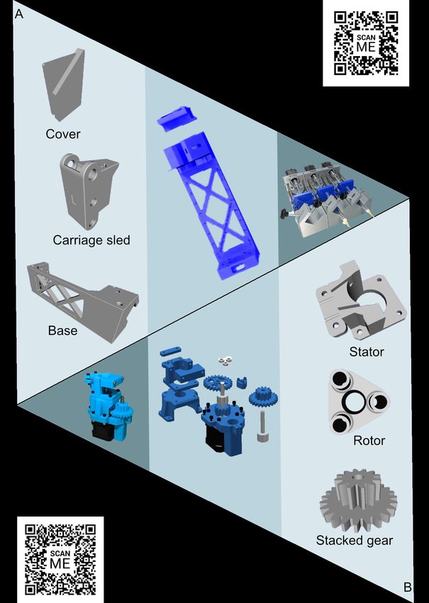
Preprints (www.preprints.org) | NOT PEER-REVIEWED | Posted: 14 May 2021                               doi:10.20944/preprints202105.0352.v1

          tion, allowing to bypass the necessity of precise mechanical
          focusing during acquisition (50).
          One of the goals to achieve wide accessibility to microscopy
          technology is to substantially reduce the price by either 3D
          printing or procuring commonly used laboratory parts. Here
          great examples are the OPN Scope that aims to lower the
          costs for fluorescence microscopy (51) and the FlyPi, which
          uses a 3D-printed mainframe, a Raspberry Pi computer, a
          high-definition camera system and Arduino-based optical
          and thermal control circuits for C200 or less. The system
          was tested in experiments involving behavioural tracking in
          C. elegans as well as Optogenetics and Thermogenetics in
          Drosophila and C. elegans (1). The miCube open-microscopy
          framework is another system of this family. It has been used
          to visualise dCas9 in vivo target search, as it is capable of
          single-molecule microscopy with high spatiotemporal reso-
          lution (13). The Microscopi project aims to democratise mi-
          croscopy with their portable, low cost, 3D printed and self-
          built systems capable of multimodal imaging (bright field,
          dark field, pseudo-phase and fluorescent microscopy). It uses
          an automated XYZt imaging system controlled by a tablet or
          smartphone using a simple GUI (52).
          Lastly, the UC2 (You. See. Too.) project is a low-cost,
          highly versatile and customisable 3D printed microscope that
          uses a modular design toolbox. The system is fully accessi-
          ble online and uses many common off-the-shelf optics and
          electronic components that are fitted in 3D printed cubes
          (Fig. 3b). It has been used to acquire macrophage cell dif-
          ferentiation data, as well as apoptosis and proliferation en-
          closed in an integrated incubator in one of the modules and        Fig. 4. 3D printed parts for fluidic control. (a) “Poseidon”: a syringe pump-based
                                                                             system that supports multiple pump arrays (25). (b) Peristaltic pump system (57).
          by minimizing axial drift with an automated focusing system
                                                                             Both systems require an external power source and can be controlled using an
          (14).                                                              Arduino board.

          Sample Manipulation, microscopy and 3D                             valves (56). Another method to control microfluidics is using
          printing                                                           pumps. Syringe pumps are simple and can be used to deliver
          3D printing applications for sample manipulation are a highly      precise volumes of liquids for various research needs (e.g.,
          versatile and powerful tool. Especially the field of microflu-     delivery of drugs to samples during live imaging).
          idics is a highly interesting target for applying additive man-    These pumps use a motor that drives the precise movement
          ufacturing, allowing to downscale biochemical applications         of the syringe plunger, resulting in accurate fluid volume con-
          to the point of creating portable and nano-scale versions of       trol. Syringe systems can be paired in multi-pump arrays that
          a testing laboratory. While originally the field was based on      facilitate multiple fluids to be pushed in and out of samples.
          moulding and replica molding fabrication, today 3D print-          While commercial systems can be expensive, 3D printed op-
          ing allows the creation of more complex geometries and de-         tions are available that are both highly efficient and highly
          signs. With this approach, the production of moving parts          modular, allowing the addition of more syringe pumps easily
          is possible, including miniaturised pumps and valves that al-      (Fig. 4a) (24, 25). The highly modular lego-and-3D-printed
          low accurate fluidics control, as well as sensors that allow the   system NanoJ-Fluidics (aka “Pumpy) is capable of managing
          detection of microchanges in the environment (Fig. 4). Addi-       up to 128 syringe pumps simultaneously (24). These systems
          tionally, the variety of 3D printing materials available allows    are controlled by Arduino controllers, allowing precise fluid
          researchers to customise the parts to suit specific needs (53).    volume manipulation.
          Functional parts such as valves are divided into manual and        Similarly to syringe pumps, fully 3D printed pumps are ca-
          pneumatic, with the former requiring manual control and the        pable of inducing flow (58). The most common pump is
          latter requiring an energy source. Several examples of valves      based on peristaltic pumps, usually consisting of three or
          exist in the literature, ranging in complexity. Simple manual      more valves along the flow channel. 3D printed peristaltic
          valves consist of an enclosed valve that allows flow when the      pumps based on planetary gear concepts are effective and can
          inside and outside channels are aligned in the opened posi-        be printed using common FDM or SLA 3D printers (Fig. 4b)
          tion (53, 54). Other more complex valves such as pneumatic         (59). These pumps can be employed in microfluidic automa-
          ones, can be printed in arrays to mimic circuits (55) or quake     tion and printed using designs that do not require posterior

          6   |                                                                                Del Rosario, Heil & Mendes et al.   |   3D printing in microscopy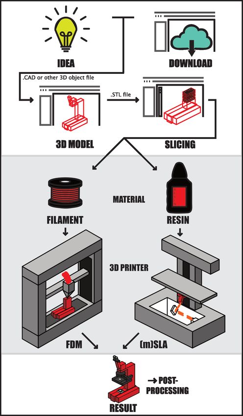
Preprints (www.preprints.org) | NOT PEER-REVIEWED | Posted: 14 May 2021                            doi:10.20944/preprints202105.0352.v1

         assembly (i.e., “print-in-place”) (60). Furthermore, they can       complete microfluidic chambers for lower prices when com-
         also be operated with Arduino controllers, allowing custom          pared to other methods. This system was used to create an in
         flow profiles for handling precise liquid volumes (57, 61).         vitro model of the circulatory system using a cardiac-like on-
         3D printed pumps also are inexpensive to print, with prices         chip pumping system. This was done using four pumps and
         going as low as C38 per channel (61). Peristaltic pumps 3D-         passive check valves to mimic the four heart chambers and
         printed using SLA can present durability issues. However,           valves. The process was later validated by emulating normal
         using thermal initiators in the liquid resin and post-processive    human left ventricular and arterial pressure profiles (74). Mi-
         baking of the component have been shown to greatly improve          crofluidics chips are perhaps the most promising in the field
         durability (62).                                                    of “organ-on-chip” research, where whole organ-like func-
         Some of these pneumatic pumps require complex ancil-                tions are mimicked using a combination of cell types grow-
         lary control tubing. However, multiplexers allow control            ing on chambers and channels inside the chip. For exam-
         over multiple valves employing only a few control channels,         ple, 3D tissue-engineered skeletal muscle (TESM) cultures
         thus facilitating the upscaling of designs and adaptation into      have been established using commercial 3D printers by using
         highly compact and complex microfluidic systems (58). Mi-           PDMS to create chambers where cells can grow. Once the
         crofluidic chips can work as sensors, detecting physical and        3D cell cultures were established in the chamber, a suspen-
         chemical changes inside chambers by measuring volumes on            sion of hiPSC-derived myogenic progenitors and biocompat-
         the picoliter scale (63–66).                                        ible hydrogels made of fibrin and Matrigel (75) was intro-
                                                                             duced. Differentiation resulted in the successful formation of
         Microfluidics devices are currently fully 3D printable (67)         a TESM culture with a comparable composition to other cul-
         with the caveat of not being able to provide transparency           tures, including myofibers (72). In addition, organ-on-chip
         (58). Printing glass-like transparent material is still not fully   managed to mimic liver interstitial structures containing en-
         attainable and severely limits their microscopy applications.       dothelial cells and primary hepatocytes (76), produce a drug
         To circumvent this issue, certain parts, such as valves, can be     screening assay to assess cell reaction (77), and test for injury
         3D printed and then combined with glass or other transpar-          (78), hepatitis B infections and even alcohol-driven injury
         ent materials such as glass or polydimethylsiloxane (PDMS).         (79). Organoids for live imaging have also been developed
         Here, for example, 3D-printed scaffolds made of ABS or              in microfluidic chips combined with a bioreactor. The biore-
         water-soluble polyvinyl alcohol (PVA) filaments have been           actor provides ideal conditions to grow cerebral organoids to
         used. A mould is then used to cover the scaffolds with              image the organoid self-assembly dynamics without transfer-
         PDMS. As soon as the PDMS has hardened, water is used               ring or disturbance. This approach facilitates examination of
         to dissolve the PVA filaments without leaving residues, while       the sample while also allowing the delivery of drugs to mod-
         ABS can be dissolved by acetone. This approach presents the         ulate organoid behaviour (80) Other organs have also been
         advantage that it allows to print directly onto the coverslips      modelled, such as the lungs (81, 82), kidneys (83, 84), intes-
         while also providing transparency, allowing excellent appli-        tine (85, 86) and heart (87, 88).
         cability for imaging (68, 69). Besides lowering costs, one of
         the advantages of using 3D printing when compared to other          Biological cages and direct sample manipulation. Sam-
         microfabrication methods is the more complex channel de-            ple holders and biological cages that are in direct contact
         signs that can be achieved, such as serpentine flow channels        with living organisms are critical imaging components. 3D
         with cross-sectional areas (67) and the compatibility with          printed parts used for these applications require biocompat-
         additional microfabrication approaches like micropatterning         ible materials that do not alter the physiology of the cells.
         (70). Additionally, by bonding printed channels to transpar-        While many strategies to ensure biocompatibility exist, gen-
         ent PMMA sheets, it is possible to produce highly complex           erally using ethanol washes together with epoxy resin appears
         arrays, such as straight, spiral, serpentine, curvilinear, and      to provide the best results, even when using clear materials
         contraction-expansion (71). In some cases, designs such as          (89). Depending on the sample holder’s nature or biolog-
         T-shape pillars are not possible to obtain via other traditional    ical cage, autoclavable material might be useful for prior-
         fabrication methods in a single demolding step, but only by         and post-sterilisation during experiments. Structures with
         using commercial 3D printers (72).                                  these characteristics require printing with advanced plastics
         3D printed microfluidic chips have been used to monitor             that provide high steam, temperature and physical resistance
         pathogenic microorganisms. For example, using an ABS                (90, 91). More information on material properties and their
         polymer and FDM 3D printing, a chip allowing bacterial              biocompatibility can be found in Table 2.
         culturing, DNA isolation, PCR and posterior detection using         An advantage of using customised sample holders and bio-
         gold nanoparticle (AuNP) probes as an indicator of Staphy-          logical cages is the possibility of tailoring them to fit different
         lococcus aureus (MRSA) was devised. A colourimetric assay           imaging platforms. Microscope parts are often expensive and
         based on the interaction between the MRSA mecA gene and             incompatible between different manufacturers or machines.
         AuNP probes was used to confirm the bacterium’s presence            This limits for example cross-instrument compatibly cutting-
         in the samples (73). An important limitation of the genera-         edge microscopy facilities, where it is common to find many
         tion of effective microfluidic chambers on these chips is the       different microscope types. To solve this, the UniverSlide
         dimension of the channels (71). The Miicraft printer was de-        project created a multi-stage, sample biological chamber that
         signed with this problem in mind and is capable of printing         can act as a holder or cage for specimens, allowing the growth

         Del Rosario, Heil & Mendes et al.   |   3D printing in microscopy                                                                  |   7
Preprints (www.preprints.org) | NOT PEER-REVIEWED | Posted: 14 May 2021 doi:10.20944/preprints202105.0352.v1
ing tension and other mechanical stimuli to determine tis-
sue properties. This process is achieved using devices that
stretch the cell/tissue sample in a controlled manner and mea-
sure mechanical properties while monitoring cellular changes
using fluorescence microscopy. Commercial cell stretchers
are available (95) but are often expensive and hard to cus-
tomize. The 3D-printed Open source Biaxial Stretcher (OBS)
was developed for this reason, improving accessibility to re-
searchers. Additionally, it is compatible with upright and in-
verted fluorescence microscopes and can perform up to 4.5
cm XY-stretches using an electronic controller (Fig. 5b) (93).
Another cell manipulation method is Atomic Force Mi-
croscopy (AFM), which uses a cantilever that provides data
on cellular characteristics such as adhesion strength, elastic
modulus, and mechanobiological properties (96–98). AFM
can also be combined with microfluidics (99), allowing accu-
rate force control and fluid manipulation inside cells. This
type of setup uses an AFM cantilever with an aperture at
the tip and an internal channel. This microfluidics cantilever
was made using SLA and two-photon polymerization (2PP
printing on a SL-printed fluidic interface). This type of can-
tilever probes provide microfluidics with AFM functionality
and are useful for precise fluid manipulation inside cells via
cell puncturing (100).
3D printing resources and technology in mi-
croscopy applications
This review aims to enable researchers who are unfamiliar
Fig. 5. 3D printed parts for sample holders and manipulation. (a) The UniverSlide
is an all-in-one 3D printed microscopy chamber for multidimensional imaging (92).
with 3D printing to implement of this approach for their own
(b) Cell stretcher used to assess tensile properties with controlled cell stretching. microscopy projects by providing a comprehensive guide of
This open-source system is directly mounted on the microscope stage allowing live available resources and technologies, including a quick start
fluorescent cell imaging (93)
guide (see "Box 3. How to 3D print" on page 16)
of living tissue and easy adaptation between microscopy sys- Databases for 3D parts. 3D printing databases exist for
tems (92). This versatile sample chamber was 3D-printed both research (e.g., NIH Exchange: a database of 3D printed
using SLA and a biocompatible HTM140 resin from Envi- parts) and more general applications (e.g., Thingiverse), pro-
siontech (Fig. 5a). The authors agreed that the system can be viding 3D printing enthusiasts the means to obtain complete
adapted to use any standard resins since glass and PDMS are 3D models. However, a complete database focused on mi-
the only materials in direct contact with the sample. croscopy projects does not exist. This represents a substan-
UniverSlide was devised to have the dimensions of a regular tial obstacle for newcomers, as information is not centralised
microscope glass slide (e.g., 26 x 76 mm2) and uses five main and can be difficult to locate because it relies on previous lit-
parts that include the 3D printed chamber frame, a bottom erature knowledge. Therefore, we compiled a 3D printing
coverslip, an agarose pad, a PDMS seal and a 3D printed lid database for microscopy applications which can be found as
with a glass slide (Fig. 5a). The sample chamber can then supporting information. .
be filled with cell culturing medium and used for microscopy
applications in unicellular and multicellular samples. Also, it Commonly used 3D printing technologies. Additive
is compatible with live and fixed samples (92). manufacturing comprises a variety of different technologies.
This type of sample chamber can also be expanded to aid ex- Although the technology itself is widely known and highly
perimental procedures. For example, a low-cost cell growth advertised, researchers unfamiliar with 3D printing technol-
chamber capable of electrical or chemical stimulation of the ogy still struggle to fully realise its potential beyond a mere
sample has been devised. Electrical stimulation in mam- curiosity. 3D printing technology has seen a sharp increase in
malian cell cultures is used to assess physiological mecha- accessibility as the technology becomes less expensive, with
nisms, generally in neuronal cells and myocytes. They are many commercial options offering basic printers for less than
also used to time-resolve intracellular calcium concentrations C100 (9). From these widely available printers, FDM and
as a direct result of inducing membrane depolarization (94). SLA stand out as the simplest and most inexpensive options
Direct sample manipulation is also possible, for example, us- for a beginner and thus, will be the focus of this review.
8 | Del Rosario, Heil & Mendes et al. | 3D printing in microscopyPreprints (www.preprints.org) | NOT PEER-REVIEWED | Posted: 14 May 2021 doi:10.20944/preprints202105.0352.v1
Fig. 6. 3D design principles to en-
sure mechanical stability, precision,
and printability. A) The overall me-
chanical stability of a 3D-printed ob-
ject is mainly influenced by the thick-
ness of it’s walls and the proper-
ties of the infill (e.g., density and
pattern). A high printing precision
can be achieved by optimizing the
print orientation, while the minimum
feature size that can be achieved
with the printing approach and ma-
terial has to be considered. Some
features, such as overhangs and
bridges, might require the imple-
mentation of support structures to
be printable. B) Examples of dif-
ferent infill densities using the “rec-
tilinear” pattern. A higher infill den-
sity contributes to the object’s struc-
tural integrity but increases the print-
ing time and material consumption.
C) Examples of different infill pat-
terns printed with a density of 20%.
“Line” and “rectilinear” patterns are
the strongest against forces applied
in the direction of their main axis, but
weak against forces in other direc-
tions. Conversely, the “honeycomb”
pattern is the weakest against forces
applied in any specific direction but
the strongest when forces are ap-
plied in more than one direction.
Several other patterns that explore
the three-dimensional space in dif-
ferent manners also exist.
Fused Deposition Modeling (FDM) is perhaps the most Furthermore, other elements besides the materials used con-
popular and cost-efficient of all 3D printing technologies. It tribute to the integrity and properties of the prints (Fig. 6a).
is versatile and flexible, with many different materials avail- Several studies have experimented with path-planning and
able to suit specific needs. The most common materials used part-orientation to alter the anisotropic mechanical proper-
in FDM are thermoplastics, but composites of thermoplastics ties of the 3D printed parts (101). The quality of the layer-
and ceramics or metal powders are also available. During the to-layer binding is also crucial as voids forming between the
3D printing process the plastic material is extruded through a layers reduce the object’s strength. An approach to improv-
heated nozzle along a predefined path and deposited layer by ing these properties is developing composite materials ex-
layer to materialise the design. The printer itself consists of a hibiting higher mechanical, electrical, and thermal proper-
platform, the print bed where the layers will be deposited in ties. These materials are produced by combining the base
a semi-solid state, a print head composed of a heating block polymer with fillers. Another approach to increase structural
and a nozzle, electric motors that move the print head, and the integrity that is highly discussed in the 3D printing commu-
filament spool holder. Once the g-code of the design is loaded nity is infill modulation. Different infill densities can create
into the printer, a 3-axis system controls the print head, mov- objects ranging from completely hollow (0% infill) to com-
ing in the x-y axis to deposit a layer with paths covering the pletely solid (100% infill) (Fig. 6b). Importantly, this choice
shape of the initial slice of the 3D design. This is followed influences the weight of the final object and the printing time
by the head or the print bed moving in the z-axis according substantially. Furthermore, the geometry of the infill pattern
to the layer thickness, and the addition of another layer using chosen is also important. For example, a study found that the
x-y axis movements as before. This process is iterated un- “rectilinear” pattern resulted in the highest tensile strength
til the final 3D model is recreated. Due to its simplicity and than the other patterns evaluated (102). However, while "rec-
fast turnaround, FDM excels at rapid prototyping. However, tilinear" excels at resisting forces applied in the direction of
the printed structure’s quality depends on a multitude of fac- the pattern’s lines, it is extremely weak against forces applied
tors, including the material used. A wide variety of materi- in other directions. Thus, a better choice might be the “cu-
als is available, of which the most common are acrylonitrile- bic” or “honeycomb” patterns, which are less resistant than
butadiene-styrene (ABS), polylactic acid (PLA), Polyethi- the “rectilinear” to forces applied in a specific direction but
lene Terephtalate Glycole modified (PETG) polycarbonate stronger in the others (Fig. 6c). Despite the many advan-
(PC), polyamides (PA), and Polypropylene (PP). Addition- tages of FDM compared to other 3D printing modalities, this
ally, FDM enables colour printing if filaments with different approach’s nature entails certain caveats. FDM is prone to
pigments are used. defects and printing artifacts that impact the printed object’s
Del Rosario, Heil & Mendes et al. | 3D printing in microscopy | 9Preprints (www.preprints.org) | NOT PEER-REVIEWED | Posted: 14 May 2021 doi:10.20944/preprints202105.0352.v1
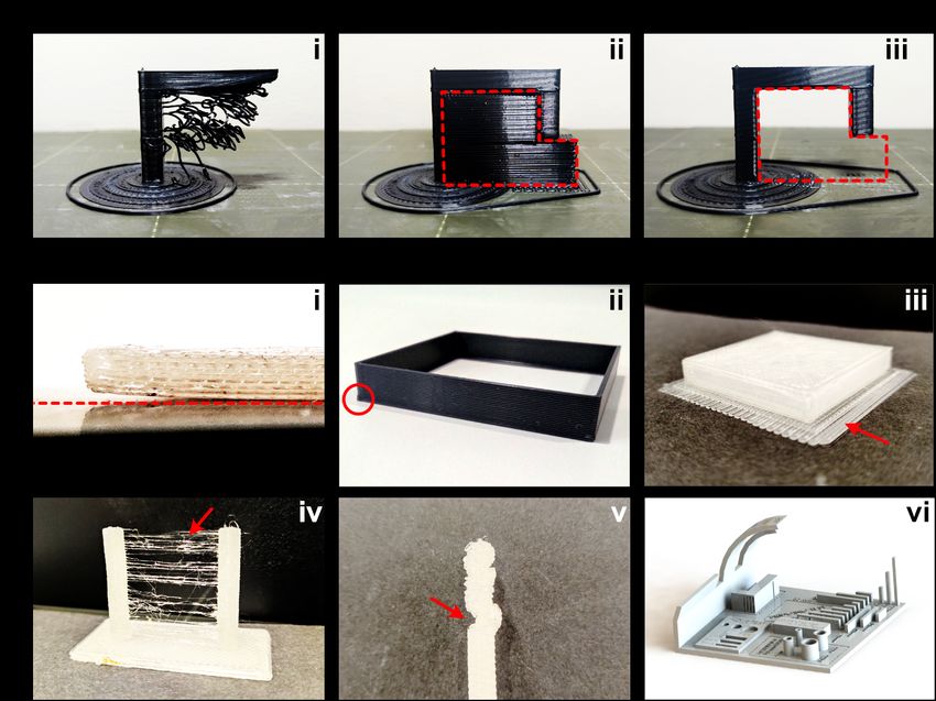
Fig. 7. 3D printing limitations, defects, and artifacts. A) Models containing overhangs require support structures to be printed. (i) Attempting to print an overhang without
support structures results in defective prints because the deposition of material requires a platform. (ii) Simple support structures (highlighted by a red box) can be included
during the “slicing” process and are printed as part of the object. (iii) After printing is finished, the support structures can be removed, and the final shape is achieved. B)
FDM is prone to several printing defects and artifacts, which can result from a multitude of factors, such as the thermodynamics of the printing environment (e.g., cooling
efficiency). (i) “Warping” or “curling” is a deformation resulting from the materials’ expansion coefficient. It produces a defective object and can lead to catastrophic failures.
The red dashed line depicts the printing plane and highlights the degree of deformation. Adequate adhesion and the use of a heated printing bed can help avoid this effect.
(ii) Conversely, high bed temperatures can lead to “Elephant’s foot”, which consists of a first layer that is wider than the subsequent layers. (iii) Printing a raft can help avoid
“warping” by increasing adhesion to the printing bed. It can also prevent “elephant’s foot” by re-directing the heat-induced deformation from the object to the layers added to
the bottom of the object. (iv) “Stringing” or “oozing” consists of thin filaments bridging different structures and results from material extrusion in between movements of the
printing head. It can be reduced by increasing printing speed, tuning of the extrusion/retraction cycles, but can also be removed posteriorly using a hot-air gun. (v) “Layer
shifting” typically occurs when the printing head collides with the object during printing, resulting in a chronic printing offset that misaligns the layers printed after the collision.
(vi) Several printing settings can be tuned to achieve a perfect printing job. The tuning procedure(s) are now quicker and easier thanks to contributions of many model creators
who upload “tuning models” to 3D model online databases. Some models are directed towards a specific tunable feature, while others, such as the one depicted, combine all
the tunable features in a single object (https://bit.ly/3tx6Oag).
aesthetics and practical applications. For example, objects Conversely, a high bed temperature and insufficient cooling
containing overhangs with more than 45 degrees require the can result in a first layer that is slightly larger than the subse-
use of supports to be printed correctly (Fig. 7a). These are quent layers, an effect known as “elephant’s foot” (Fig 7bii).
often removed manually but can also be removed chemically This deformation is especially problematic in objects that re-
if special dissolvable materials are used to produce them, the quire a precisely defined shape, such as a part intended to
most common being the water soluble PVA. The support re- fit a tight slot. Elephant’s foot is more frequent in larger
moval process results in rough surfaces that require sanding prints, in which the weight of the object presses down on the
or polishing to be smoothened (103). partially-cooled first layers. A nozzle positioned too close to
Several printing artifacts can result from a multitude of fac- the printing bed may also generate this effect by forcing the
tors (Fig. 7b). “Warping” is a curling deformation often ac- extrusion of material beyond the predicted line width. Thus,
companied by a partial or complete detachment of the object “elephant’s foot” is typically solved by adjusting the printer’s
from the printing bed (Fig. 7bi). It can result in catastrophic settings and environment. Another solution for warping and
failure if the deformation causes the object to intercept the “elephant’s foot” is printing a raft, which is an additional and
nozzle’s path. Warping occurs as a result of the materials’ wider first layer meant to be damaged in place of the original
expansion coefficient. When the material is melted before first layer (Fig. 7biii). Similar to supports, rafts need to be
extrusion, it first expands and then shrinks slightly when it removed after the printing job is finished, resulting in rough
cools down. Thus, warping is more common in materials surfaces that might require post-processing.
with higher melting temperatures (e.g., ABS), and it can be Another common printing artifact is “stringing” or “oozing”,
minimised by controlling the printing environment, for exam- which happens when material is extruded while the nozzle
ple, using heated printing beds and enclosed build chambers. is moving to a new location (Fig. 7biv). Consequently, thin
10 | Del Rosario, Heil & Mendes et al. | 3D printing in microscopyPreprints (www.preprints.org) | NOT PEER-REVIEWED | Posted: 14 May 2021 doi:10.20944/preprints202105.0352.v1
Table 1. Commonly used 3D printing technologies for microscopy applications. Fused deposition modeling (FDM) and Stereolithography (SLA) are two 3D printing technolo-
gies with different applications. FDM is generally more suitable for inexpensive, rapid prototypes with modest structural complexity and substantial mechanical properties,
while SLA is more suitable for highly intricate objects where high mechanical impact is not present.
strings of plastic are left behind. Possible solutions to over- acteristics that are comparable or even better than FDM ma-
come “stringing” are increasing the speed at which the ex- terials in terms of flexibility or hardness, heat resistance, sol-
truder moves to reduce the time during which material is vent resistance. Due to its unique printing method, SLA can
extruded between movements, or increasing the speed and confer anisotropic properties to the printed materials and pro-
length of “retraction”, where the filament is pulled back be- vide the highest possible resolution, accuracy, and smoothest
fore moving the nozzle in a new position. In contrast, increas- surface of all 3D printing technologies. For this reason, SLA
ing the movement speed past the capabilities of the printer’s is widely used in the industry to create prototypes with in-
motors might result in material extrusion before the nozzle tricate patterns, casting, and moulding. SLA printers usually
reaches the desired position. Thus, the layer(s) printed will use a laser for curing the resin. This process is, however,
be misaligned with the previous layers, causing a catastrophic slower and more complex than FDM printing. In addition
artifact named “layer shifting” (Fig. 7bv). Tuning a 3D to this, the layers of the SLA print can go as low as 25µm,
printer to avoid these and other printing artifacts is now eas- making the printing process slower than a standard FDM. In
ier due to the availability of several 3D models that can be recent years, masked SLA (mSLA) printers have reached the
used to optimise specific printing settings. Some tuning mod- consumer market. If the chemical process is similar to the
els are directed towards tuning a specific aspect, while others SLA -crosslinking resin using UV light- the way the light is
are “all-in-one” models that combine multiple features of 3D processed is different. Whereas in the SLA, a laser is em-
printing (Fig. 7bvi). ployed, in mSLA a set of UV LEDs is used for the crosslink-
ing process, and an LCD on top of them will control where
Stereolithography (SLA) is the oldest form of 3D print- the UV light passes, effectively using the transparent or black
ing (104). As it is a highly versatile and accurate form of LCD pixels as mask lithography. Thanks to this ingenious
3D printing, although beeing more expensive, the intricate method, those printers are equally or even more inexpensive
details it can produce are fairly superior to the FDM. Instead than) FDM printers, and, as they cure one complete layer at a
of using thermoplastics like FDM methods, it uses thermoset time without the need of moving a laser (or a printhead), they
liquids -in the form of liquid resins- cured by UV light. Here, are also faster than SLA or FDM. The inexpensive availabil-
UV light selectively illuminates a small liquid resin area, trig- ity of those printers, together with their speed and precision
gering initiators and photo-polymerising it via radical poly- may open the possibility of using mSLA printers in the lab
merization, an exothermic process (105). The polymerisation (72). Both FDM and (m)SLA technologies are usually com-
triggered by these initiators creates covalent bonds between pared based on availability, cost, the durability of the mate-
the liquid resin monomers. Two transition states occur during rials, and the level of structural details provided (see Table
this light-based curing process: gelation, where the material 1).
transitions from liquid to rubber, increasing its viscosity; and
vitrification, where the rubber-like material transitions into Materials for 3D printing. Besides the printing technology
a solid resin (105). This process is done in layers but due and the 3D-design, one crucial factor defining the quality and
to the use of resin materials, the material’s physical proper- physical properties of the 3D-printed component is the mate-
ties such as tensile strength and flexibility are usually inferior rial choice. Thus, a lot of effort is taken to optimise material
when compared to FDM. To overcome this limitation, mate- composition to increase the printability and print quality, but
rial manufacturers are constantly creating new formulations also to enhance physical properties like strength, flexibility,
and, in some cases, were able to create resins presenting char- and biocompatability (106), or optical properties (107).
Del Rosario, Heil & Mendes et al. | 3D printing in microscopy | 11You can also read