Mechanisms, influencing factors, and applications of electrohydrodynamic jet printing
←
→
Page content transcription
If your browser does not render page correctly, please read the page content below
Nanotechnology Reviews 2021; 10: 1046–1078
Review Article
Shuxiang Cai, Yalin Sun, Zhen Wang, Wenguang Yang*, Xiangyu Li*, and Haibo Yu
Mechanisms, influencing factors, and
applications of electrohydrodynamic jet printing
https://doi.org/10.1515/ntrev-2021-0073
received July 31, 2021; accepted August 20, 2021
Abstract: E-jet printing is a micro- and nano-manufac-
turing technique that utilizes electric field-induced fluid
jet printing for achieving better control and resolution than
traditional jet printing processes. In addition to high print-
ing resolution, E-jet printing has advantages in some
Graphical abstract
aspects such as wide material applicability, which has
been successfully applied in numerous applications that
industries. The manufacturing of multimaterial and multi-
include sensors, transistors, tissue engineering scaffolds,
scale structures is the current research hotspot of manu-
and photonic devices. This article reviews the electrohydro-
facturing science. The photolithography can fabricate
dynamic jet (E-jet) printing technology, which mainly relies
microstructures with a size of less than 100 nm and plays
on the principle of electrohydrodynamic-induced fluid
a key role in the development of miniaturization and
movement. At the same time, the process of jet formation
high integration of electronics and semiconductors [1–5].
and droplet deposition is described. The parameters, nozzle
Moreover, microfabrication/nanofabrication based on photo-
design, and ink characteristics of the jet printing process are
lithography and soft lithography is mainly focused on man-
summarized. Then, a number of concrete applications based
ufacturing 2D structures, which cannot meet the increasing
on E-jet printing processes are described in this article. Finally,
demand for 3D structures such as flexible electronic devices,
the future development of this technology has been prospected.
stents, and so on.
Keywords: electrohydrodynamic jet printing, droplet gene- In contrast, additive manufacturing technology deposits
ration process, electronic devices, bioprinting functional materials on the substrate directly, which can
achieve precise control point-line-surface step-by-layer
manufacturing. As a typical additive manufacturing pro-
cess, the inkjet printing method can realize the deposition
1 Introduction and patterning of functional materials in a drop-on-
demand manner. It has attracted great attention in the
The technology of fabricating structures at microscale manufacture of flexible electronic devices since electronic
and nanoscale is critical to many existing and emerging materials provide huge opportunities for the printing tech-
nology. Due to its pure additive operation, large-area pre-
paration, low-temperature process, and low cost, inkjet
* Corresponding author: Wenguang Yang, School of printing has become an effective electronic manufacturing
Electromechanical and Automotive Engineering, Yantai University, technology to fabricate electronic devices such as transis-
Yantai 264005, China, e-mail: ytu_yangwg@163.com tors, light-emitting diodes, and sensors [6–11]. In addition,
* Corresponding author: Xiangyu Li, School of Basic Electrical
inkjet printing is also applied in the fields of optics and
Engineering, Naval Aviation University, Yantai 264005, China,
e-mail: rainlw@126.com biology [12,13]. Thermoelectric or piezoelectric-driven nozzle
Shuxiang Cai, Yalin Sun, Zhen Wang: School of Electromechanical droplets successfully deposit functional materials on the
and Automotive Engineering, Yantai University, Yantai 264005, substrate. Relevant studies have been carried out based on
China a variety of different materials, from polymers [14], metals or
Haibo Yu: State Key Laboratory of Robotics, Shenyang Institute of
metal oxides [15–18] to various biological materials [19–21].
Automation, Chinese Academy of Sciences, Shenyang 110016,
China; Institutes for Robotics and Intelligent Manufacturing,
However, the traditional inkjet printing technology is limited
Chinese Academy of Sciences, Shenyang 110016, China by the size of the inner diameter of the nozzle, and the size of
Open Access. © 2021 Shuxiang Cai et al., published by De Gruyter. This work is licensed under the Creative Commons Attribution 4.0
International License.
Electrohydrodynamic jet printing 1047
the droplets produced is usually larger than the inner dia- 2 The principle and theoretical
meter of the nozzle. Printing smaller droplets requires the
design and manufacture of micron-level nozzles. At the
analysis of E-jet printing
same time, small droplets require a greater driving force,
and it is difficult to print high-viscosity materials. The exis- 2.1 Electrohydrodynamic printing systems
tence of these limitations makes inkjet printing difficult to
meet the urgent needs of the manufacturing field of micro- A typical E-jet printing system is composed of a pressure
nano devices. The resolution and accuracy of microstruc- pump, a nozzle, a voltage source, a mobile platform, and
tures based on laser technology are relatively high, but the a computer control system. The pressure pump pushes
process relies on expensive optical systems, and materials the ink to be injected into the nozzle, and the voltage
are limited to specific photosensitive polymers, which pre- source provides the electric field between the nozzle
vents its widespread use. Moreover, compared to conven- and the substrate. The system diagram of E-jet printing
tional fabrication methods such as photolithography, E-jet is shown in Figure 1(a) [37]. Different from traditional
printing has attractive features including a simple fabrica- inkjet printing, E-jet printing uses a high-voltage electric
tion process, applicability on flexible substrates, compat- field to induce the fluid movement instead of squeezing
ibility with large-area substrates, and low fabrication cost force. When the liquid obtains a sufficient high electric
for printing electronics. potential, the liquid meniscus forms a stable cone shape,
Electrohydrodynamic jet (E-jet) printing, a maskless, which is called the Taylor cone. The electric field force is
noncontact, direct writing, and additive manufacturing used as the driving force to pull the polarized droplet
process, provides a reliable solution to break the con- from the tip of the Taylor cone. When the electric field
straints of the aforementioned manufacturing process. force overcomes the surface tension of the droplet, the
E-jet printing technology utilizes an electric field to induce droplet is released from the nozzle tip and the size of the
the fluid movement, to stretch ink droplets until the dro- ejected droplet is much smaller than the inner diameter
plets break, and to finally obtain a high-resolution 2D pat- of the nozzle. Then, according to the designed pattern,
tern [22–27]. Besides, through layer-by-layer printing, E-jet the mobile platform composed of the substrate and the
printing could achieve 3D microstructure/nanostructure three-axis electric translation stage is moved to deposit
fabrication, which provides strong support for the devel- the droplets on the specified position accurately, and a
opment of the biological field [28–36]. E-jet printing tech- large-area droplet array is obtained, as shown in Figure
nology maintains the advantages of the traditional inkjet 1(b) [37].
printing technology, such as high flexibility and large area
printing. Furthermore, it could achieve high-resolution
manufacturing at sub-microscales and can print high-visc-
osity solutions. Printing accuracy is no longer limited by 2.2 Theoretical analysis of E-jet printing
the inner diameter of the nozzle, and droplets with a size
much smaller than the nozzle size could be produced. The dynamic behavior of the electrofluid is affected by
Therefore, E-jet printing technology has broad application the combination of various forces such as liquid pressure,
prospects in the future development. liquid surface tension, and electric field force. The vol-
Although the development of E-jet printing has been tage, flow rate, and the properties of ink such as viscosity,
summarized by other researchers, the theoretical analysis conductivity, and surface tension are important factors
and newly emerging applications are missing. As a con- affecting the formation of jet modes [38–40]. The mechanism
sequence, there is an urgent need for a comprehensive of the jet formation process is essential for optimizing
and systematic review on this technique. In this article, electro-jet printing parameters and achieving stable jetting
we mainly review the development of E-jet printing. and high resolution. Therefore, before conducting prac-
Section 2 introduces the principle of E-jet printing and tical operations, it is necessary to establish a mathematical
some theoretical research carried out by researchers. and physical model for the theoretical analysis of the influ-
Section 3 demonstrates three factors that mainly affect ence of various parameters.
E-jet printing: process parameters, nozzle design, and First, jet formation and deposition are of great sig-
ink characteristics. Section 4 summarizes the application nificance to the resolution and accuracy of jetting. The
of E-jet printing, from the two aspects of flexible electronic droplet generation process directly affects the adjustment
devices and biological application. Section 5 discusses the of process parameters and the performance of the electro-
development prospects of E-jet printing technology. fluidic jet printing structure during the preparation of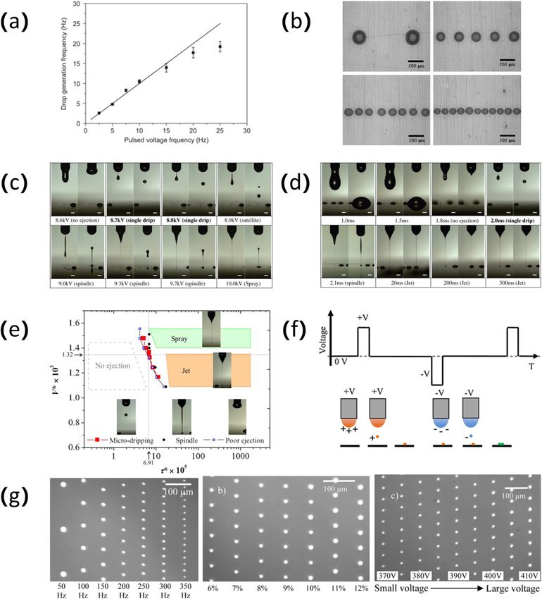
1048 Shuxiang Cai et al. Figure 1: (a) The composition diagram of the electrofluidic power jet printing system. (b) A droplet pattern array with an average diameter of 2.8 μm printed by the E-jet printing system. Reproduced from ref. [37] with permission from Elsevier Ltd. micro-nano-scale functional structures. Simulation of the ensuring stable and continuous injection flow rate, and E-jet printing process is indispensable for the controll- nozzle diameter on printing accuracy. Surface tension ability of the system. Collins et al. [41] found that the and electrostatic force play a key role in the formation of droplet under the action of a strong electric field can droplets. The relationship between these two forces is produce three different states by changing its conduc- helpful to analyze the droplet ejection and deposition. tivity. The deformation of the droplet, the formation of As shown in Figure 2(c) [43], a finite element analysis Taylor cones, and the pinch-off state of the droplet are model of the droplet surface charge and electrostatic field clearly displayed in the simulation, as shown in Figure 2(a) distribution is established [43]. Based on this model, the [41]. Pan and Zeng [42] established a physical model based droplet formation process is analyzed and the relationship on a variety of coupled physical forces such as electrostatic between electrostatic force and process parameters is force, surface tension, hydrodynamic force, viscous force, determined. At the same time, the flight speed of the dro- and gravity, as shown in Figure 2(b) [42]. The whole pro- plet was calculated, and the droplet reached the maximum cess of droplet generation in a complete cycle was simu- when it hit the substrate, and then, the deposition of the lated and experimentally completed, including Taylor cone droplet was simulated. The trajectory of the jetted droplets generation, jet start, jet interruption, and jet contraction. under the action of an electric field is very important for The numerical model is used to further study the effect the precise control of droplet deposition. Wu et al. [44,45] of three parameters including injection starting voltage, analyzed the electric field distribution through a finite
Electrohydrodynamic jet printing 1049
Figure 2: (a) The detailed process diagram of the droplet deposition, from the spherical shape to the Taylor cone at both ends and then to
the droplet pinching off. Reproduced from ref. [41] with permission from the National Academy of Sciences. (b) Coupling distribution map
of various forces of cone jet ejection based on the dielectric model. Reproduced from ref. [42] with a permission from MDPI (Basel,
Switzerland). (c) Finite element analysis of the hemispherical meniscus at the tip of the nozzle and the surrounding electric field distribution
map. Reproduced from ref. [43] with a permission from Elsevier BV.
element model and found that the electric field intensity at is due to the pressures on both sides of the interfacial
the nozzle tip is the largest. High voltage, low distance surface ( pℓ and pg ):
between nozzle and substrate, and small nozzle size can
Grad p = pℓ − pg . (4)
enhance the intensity of the electric field. Due to the
uneven electric field at the nozzle tip, the direction of the The force density on the liquid jet can be obtained
droplets ejected from the edge of the nozzle is deflected; using equations (3) and (4):
however, the droplets ejected from the center of the nozzle ∂ρℓ vℓ
are not deflected. = ρℓ g + Lℓ − ϕst − ∇⋅(Grad(lp)) + ηℓ ∇vℓ
∂t (5)
The jet process of a conventional E-jet system could
+ ρℓ vℓ ⊗ vℓ.
be calculated using a set of equations in which electrical
and mechanical forces are included [46]. In addition, during the E-jet printing process, the
n droplets may be broken down into tiny satellite droplets
∂ρi
+ ∇⋅(ρi vi ) = ∑ Iij , (1) [47–50], which is undesirable to obtain in the printed pat-
∂t j=1
tern because it will affect the resolution of the printing.
n
∂ρi vi Therefore, it is very necessary to analyze and study satel-
+ ∇⋅(ρi vi ⊗ vi ) = ∇⋅ ∏ + ρi g + ∑ Pij + Lℓ . (2)
∂t ℓ j=1 lite droplets in the process of droplet formation. Huo et al.
[51] not only discussed the process of droplet formation
In equation, i refers to gas or liquid phase (g and ℓ,
and the transition of ejection mode but also studied the
respectively). The symbol ⊗ denotes the dyadic product
formation of satellite droplets in the drop mode and
of the vectors.
whether they aggregate with the main droplet. As shown
The stress tensor on the liquid surface was formula-
in Figure 3(a) [51], for low-viscosity liquids, when no elec-
rized as follows:
tric field is applied, the downward contraction force
∏ = Grad(lp) + ηℓ∇vℓ, (3) caused by surface tension (Fσ1), the upward contraction
ℓ
force caused by surface tension (Fσ2), and gravity (Fg)
where p is the dynamic pressures and η is the liquid are three forces that determine the direction of the move-
viscosity. Grad is a difference operator on a scalar, which ment of the droplet. After the electric field is applied, the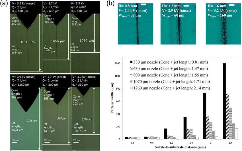
1050 Shuxiang Cai et al. Figure 3: (a) Schematic diagram of force action of satellite droplets produced by low-viscosity liquid with or without the electric field. Reproduced from ref. [51] with permission from American Institute of Physics. (b) Several different injection modes as the electric field and flow rate change. Reproduced from ref. [53] with permission from Cambridge University Press. (c) Changing the nondimensional parameters of flow rate α and voltage β changes in injection behavior. (d) Four mixed ink (E10T0, E8T2, E4T6, and E2T8) jet behavior diagrams drawn according to flow rate α and voltage β. Reproduced from ref. [60] with permission from American Chemical Society. electric power (Fd) from the charged main drop and the Second, due to the interaction of various factors Coulomb repulsive force (Fe) from the electric field between during the E-jet printing process, different jetting modes the electrodes dominate. This study shows that when the are formed. As Collins et al. [53] and Jaworek and Krupa number of electronic bonds is low, the satellite droplets [54] summarized in their article, the injection modes move upward until they gather with the meniscus, and include drip mode, pulsation mode, stable cone injection when the number of electronic bonds is high enough, the mode, and complex injection modes, such as oblique satellite droplets will reciprocate up and down between the injection, double injection, and multiple injection, as two meniscuses. Guo et al. [52] used numerical simulation shown in Figure 3(b) [53]. In the case of low electric field methods to study the generation and ejection behavior of strength and low flow rate, the electrostatic force pro- satellite droplets because the charge relaxation time deter- duced by the electric field offsets the surface tension, mines the electrical repulsion between the satellite droplet and the droplets are clamped off from the nozzle under and the meniscus. The charge relaxation time is used to the action of gravity to produce dripping. Before the flow study whether the satellite droplet will merge or separate rate increases to the minimum flow rate that can produce with the meniscus. Results have shown that a longer charge a stable cone jet mode, the nozzle presents a hemisphe- relaxation time will help the satellite droplets merge with rical or Taylor conical meniscus. Unlike the dripping the meniscus, while a too short charge relaxation time will mode, this pulsed jet mode does not shrink the meniscus cause the satellite droplets to fall. At the same time, the after the droplets are separated. The dripping and pul- dielectric constant and flow affect the charge relaxation time. sating modes can be produced only within a limited flow

Electrohydrodynamic jet printing 1051
rate and voltage range. When the voltage exceeds a cer- influencing the charge convection. Therefore, there are
tain critical value, the electric field forces the droplets to 10 variables determining the electrodynamics and fluid
cause a spindle shape. This mode is called the spindle dynamics for E-jet printing: ρ, γ, ε0, ε′, K, η, d, L, Qs, and
mode. When the voltage value increases to the critical Va. Then six dimensionless numbers D1–D6 are designed to
voltage, a stable cone jet pattern is generated, the liquid systematize the 10 influencing variables. These dimension-
forms a regular Taylor cone at the nozzle, and the jet is less numbers are respectively related to processing time
ejected symmetrically along the axis. A further increase (D1), material properties (D2 and D3), geometry (D4), and
in the electric field leads to an imbalance between the processing conditions (D5 and D6). The cone jet is produced
various forces, thus producing oblique jets. The voltage in the balance of flow and electric field intensity. The
value continues to increase, and multiple jets will be mixtures of ethanol and terpineol were injected using
generated from the meniscus, resulting in dual jets or different proportions. Figure 3(c) [60] shows the injec-
even multiple jets. Among them, the pulsating jet mode tion behavior corresponding to different flow rates and
and the stable cone jet mode are essential for depositing voltages. According to the classical injection mode, the
functional materials on the substrate to obtain high-reso- injection diagrams between different flow rates and vol-
lution micro-nano structures. tages under different material properties are drawn, as
There have been many studies on the ejection mode shown in Figure 3(d) [60]. To obtain a stable cone jet,
and droplet formation process of E-jet printing. For pul- the ratio of the electric normal force to the electric tangen-
sating ejection and cone ejection modes, various scaling tial force on the surface of the Taylor cone is proposed as a
laws [55–58] for the influence of various parameters such parameter to evaluate the degree of stability. The value
as voltage intensity, flow rate, and conductivity on the becomes smaller and the stability increases. In the case
size of the droplet has been proposed. Hartman et al. [55] of the inherent pulsation of the liquid jet, the proportional
first proposed a model that can calculate the shape of relationship related to the jet diameter is proposed [57].
the liquid cone and jet, and electric field strength, charge The jet diameter is proportional to the square root of the
density, and current passing through the cone. The nozzle size and inversely proportional to the electric field
error between the experimental result and the simulating strength, which provides a theoretical basis for the study
result is within 10%, which provides a theoretical foun- of the influence factors of the jet process. From the theo-
dation for subsequent research. Scheideler and Chen [59] retical analysis, Lee et al. [61] obtained the model of the
studied the scaling law for controlling the minimum flow initial voltage for the transition from the drip mode to the
rate of a stable Taylor cone jet ejected from a charged pulsation state, the threshold voltage for the transition
nozzle. At low viscosity, the minimum flow rate does from the pulsation mode to the stable cone jet mode,
not depend on the nozzle diameter, but strongly depends and the relationship between the droplet diameter and
on the conductivity of ink. In contrast, the minimum flow the voltage. At the same time, the jet state of four different
rate of a high-viscosity liquid is basically independent of surface-active waters before and after reaching the initial
the conductivity of the liquid, but strongly depends on voltage was studied. Among them, the stability of the pul-
the nozzle diameter. Most of the previous studies only sating drop of cations was the best.
analyzed the cone jet from a single aspect of material
properties or printing parameters. It is necessary to study
the effect by combination of these two aspects of the
system. Therefore, Lee et al. [60] systematically analyzed
the influence of processing parameters and ink charac-
3 Influencing factors of E-jet
teristics on obtaining a stable Taylor cone jet pattern. printing
During the printing process, the charges move toward
the surface and cause the electric normal stress [τE,n]. The The droplet ejection process is affected by many factors,
charge conduction was influenced by the supplied flow such as ink properties (viscosity, conductivity, surface ten-
rate Qs (related to the resistance, ∼K−1) and electrical char- sion), process parameters (applied voltage, flow rate), and
ging time (related to the capacitance, ∼ε0ε′). The surface nozzle structure (nozzle diameter and nozzle design; Table 1).
charges induced by charge conduction lead to electric These influencing factors as the input of the system play a
tangential stress along the surface meniscus with accelera- vital role in the output (droplet size, ejection speed) of the
tion toward the cone apex. A jet is formed by these charge E-jet printing system. Recently, Mohammadi et al. [62] through
and fluid motions. Electric field (E = Va/L), the charge numerical simulation analysis found that the dielectric
amount (ε′), and the flow resistance (η) are the variables constant, conductivity, flow rate, voltage, viscosity, and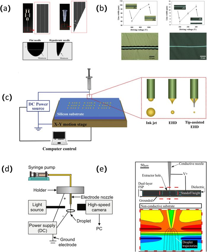
1052 Shuxiang Cai et al.
Table 1: Influencing factors of E-jet printing
Influencing factors of E-jet printing Results of influence
Process parameters
Electric field strength Increasing the voltage will reduce the droplet size
Moving speed of nozzle The line width and the line height did not change significantly
The distance between the nozzle and the As the distance increases, liquid jet on the substrate become viscous
substrate
Nozzle design
Structure The meniscus formed at the end of a hypodermic needle is much smaller and the
nonconductive tip help form a stable jet
Multi-nozzles The high production rate
Ink characteristics
Surface tension The pulse duration decreases with increasing surface tension
Density Larger particles in the ink will lead to the formation of satellite droplets
Viscosity The printing jet volume increases with the increase of viscosity
Conductivity The printing jet volume decreases with the increase of conductivity
nozzle diameter have a greater influence on the diameter studied the effects of voltage, plotting speed, and pressure
of the droplet. The speed of the droplet produced is mainly on the stable electrohydrodynamic cone jet mode. As
affected by the voltage, the distance between the nozzle shown in Figure 4(a) [64], low voltage, higher plotting
and the substrate, and the conductivity. The three para- speed, and higher pressure result in a skewed cone jet.
meters of viscosity, voltage, and dielectric constant are The larger electrostatic stress caused by the large voltage
related to the breaking distance of droplets. Among all input and small pressure indicates a larger jetting speed. There-
parameters, voltage, dielectric constant, nozzle height above fore, it is very important to match the jetting speed and the
the substrate, viscosity, and conductivity are the most effec- plotting speed. When the jetting speed is lower than the
tive parameters for process output. plotting speed of the platform, the skewed cone jet is pro-
duced. When the jetting speed matches the plotting speed,
a straight cone jet is obtained. When the jetting speed is
3.1 Process parameters higher than the plotting speed, wavy filaments are pro-
duced due to the speed mismatch. However, if the applied
E-jet printing is the result of the coupling of various driving voltage is higher than the threshold voltage, elec-
forces such as electrostatic force and surface tension. trical breakdown may even occur. According to reports,
To obtain a stable printing process and high-resolution after the start of the jet, the driving voltage is gradually
printing results, it is necessary to adjust and optimize the reduced, and the jet can still be jeted continuously,
process parameters, such as electric field strength, flow depending on the molecular weight (Mv) and weight per-
rate, the distance between the nozzle and the substrate, centage (wt%) of the solution [65]. Jang et al. [65] studied
and the moving speed of the mobile stage. Among many the ejection behavior through the relationship between the
factors, the applied voltage is the main factor. Generally, ratio R of the driving voltage Vd and the threshold voltage
increasing the voltage will reduce the droplet size (better Vth, Mv, and wt%. The jet behavior of different solutions is
resolution) and increase the ejection frequency of the similar under high R value, and the value of Mv and wt%
droplets because the higher voltage and the electric field should be increased to obtain a thinner jet under low R
strength increase the surface charge density at the Taylor value. The low R value causes the solvent of the jet to
cone. Therefore, a small droplet can obtain a large enough evaporate before reaching the substrate, and solid fibers
electrostatic force to overcome the surface tension, so as to are formed on the substrate. Changing the polymer weight
be ejected from the tip of the cone. The high electric field percentage, molecular weight, and voltage drop rate leads
also increases the rate of surface charge accumulation. to the transition of the jet mode. At high concentrations, the
Therefore, the frequency of droplet formation and ejection R value is reduced, and the transition from micropatterns to
also increases. For example, Han et al. [63] increased the nanopatterns to nanofibers can be realized, and low-voltage
voltage value from 850 to 1,000 V. Correspondingly, the driving high-resolution pattern printing can be achieved.
droplet size was reduced from 15 to 7 μm, and the printing The E-jet printing process has great potential in man-
speed was increased from 6 to 22 Hz. Wei and Dong [64] ufacturing 3D microstructures [66–69]. The line width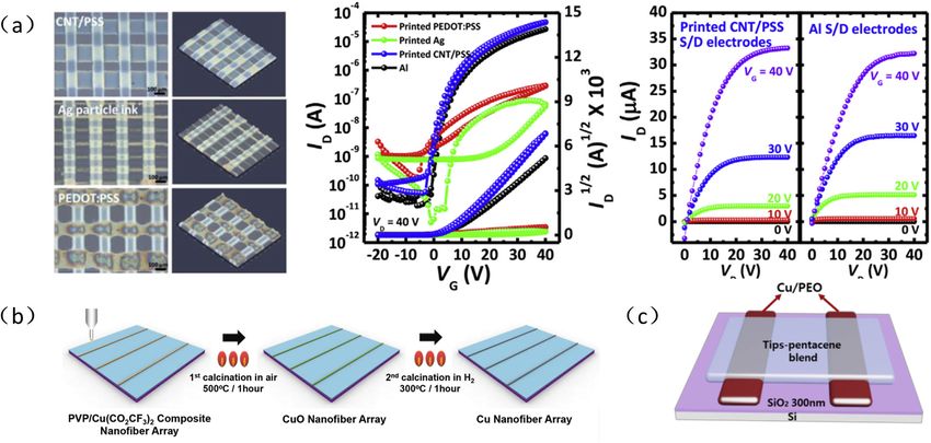
Electrohydrodynamic jet printing 1053 Figure 4: (a) The cone jet shapes and jet filaments under different voltages, plotting speeds, and pressures. Reproduced from ref. [64] with permission from Elsevier BV. (b) The effect of changing the applied voltage, the distance from the nozzle to the substrate, and the moving speed of the nozzle on the line width of E-jet printing. Reproduced from ref. [72] with permission from American Institute of Physics. and the shape of the 3D pattern are significantly affected change significantly for different nozzle speeds. As the by the operating parameters. In previous studies, the applied voltage increases, the line width increases and structure shape was affected by the moving speed of the the printing height decreases. As the distance from the collector [70,71]. While the electro-hydrodynamic direct nozzle to the substrate increases, the water fully evapo- writing proposed by He et al. [72] designed the nozzle as rates during the printing process, causing the liquid jet on a moving part, the line width and the line height did not the substrate to become viscous and the diffusion effect is
1054 Shuxiang Cai et al.
reduced, so the line width becomes smaller and the line precise control of the generated droplets can be achieved
height increases. The printing results of changing different by selecting a high-frequency voltage and a large flow
parameters are shown in Figure 4(b) [72]. Zhang et al. rate. Han and Dong [78] studied high-resolution E-jet
[69] proposed a hybrid mechanism composed of E-jet printing based on molten metal jetting. They character-
printing and fused deposition modeling technology, which ized the impact of electrostatic field and printing speed
optimizes and adjusts the printing parameters comprehen- on the printing process. This system could produce dis-
sively in terms of nozzle size, voltage, printing speed, tem- continuous metal lines using a voltage of 1,000 V. Mean-
perature, and feed speed. The results show the limitations while, if the voltage increased to 1,500 V, a continuous
of printing with large nozzles. When certain conditions thin wire with a diameter of about 40 μm is obtained.
are reached, large nozzles make the ejection behavior Printing speeds that are too fast or too slow will also
unstable. Temperature affects the viscosity of the printing cause discontinuous structures. At a printing speed
material, which in turn affects the line width. In a certain of 3–5 mm/s, fine metal wires can be printed. The jet
temperature range, the line width decreases when the tem- breaking before reaching the substrate seriously affects
perature rises. Finally, a eight-layer 3D stent with a resolu- the quality of the pattern. Because the cone length and jet
tion of 10 μm was printed under the best conditions of a length are affected by the intensity of the electric field,
nozzle inner diameter of 200 μm, a temperature of 240°C, a they decrease as the voltage increases. As the nozzle size
voltage of 1 kV, and a printing speed of 35 mm/s. Similarly, decreases or the flow rate increases, the starting voltage
He et al. [68] achieved the layer-by-layer printing line by to form the cone jet also increases, so the length of the
optimizing the voltage and the moving speed parameters cone and jet decrease, as shown in Figure 5(a) [79].
of the collector under 800 V and 20 mm/s. The average Therefore, to improve the printing quality to obtain a
thickness of the printed wall below 100 layers is about small line width and avoid spray deposition due to jet
0.71 μm. Due to the change of the electric field between breakage, Park et al. [79] set the distance between the
the nozzle and the substrate, as the number of layers nozzle and the substrate to be less than the sum of the
increases, the average thickness increases. If the number cone and the jet length under the conditions of a given
of layers is too high, the printed structure will deform in voltage, nozzle size, and flow rate. As shown in Figure 5(b)
the vertical direction. Therefore, the maximum height of [79], the line width of 32 μm is obtained at the distance
the multilayer 3D structure printing is often limited by the from the nozzle to the substrate of 0.8 mm. The small
distance between the nozzle and the substrate. If 3D micro- nozzle-to-substrate distance and the nozzle diameter do
structures are to be stacked layer by layer, the distance not affect the spray size, and the increase of the nozzle-
between the nozzle and the substrate must be changed to-substrate distance leads to the appearance of satellite
accordingly [73]. droplets. The relationship between the various process
Liquid deposition rate and liquid size are output parameters plays an important role in determining the
parameters affected by input parameters and are also size of the printed droplets. Hassan Saba et al. [80] estab-
the most important parts of a system. Researchers ana- lished mathematical models among various process para-
lyze and describe the printing results from different pro- meters through five steps: charge transfer time and ink
cess parameters [74–76]. Yuan et al. [77] proposed a transfer time, minimum voltage generated by droplets,
method of using low conductivity to generate adjustable pulse frequency, duty cycle, and speed of the mobile sta-
pulsating cone jets. The entire cone jet is divided into tion. Based on these mathematical models, to obtain a
three stages: liquid accumulation, Taylor cone formation, droplet with a diameter of 140 μm, a voltage of 2.5 kV, a
and multiple emissions. The Taylor cone formation time pulse frequency of 20 joints, a duty cycle of 41.3%, and
is significantly affected by the voltage frequency. Due to an XY stage speed of 6 mm/s were determined.
the large nonelectrical time at low voltage frequencies, To obtain better printing performance, it is necessary
the Taylor cone formation time changes little at frequen- to adjust and improve the printing parameters. Usually, a
cies below 30 Hz. The deposition frequency in a cycle DC voltage is applied to an E-jet printing system, which
decreases as the voltage frequency increases, and the has limitations in controllability. Due to the coupling of
flow rate has only a slight effect. At the same time, the process conditions, it is difficult to control droplet size
droplet size also decreases with the increase of the vol- and printing rate separately. The jet of E-jet printing can
tage frequency. But using a large flow and sufficient naturally generate a pulsed flow, and the frequency of the
liquid supply can compensate for the liquid loss after jet and the size of the generated droplets can be regulated
launching and slow down the rate of decrease. A stable by changing the voltage [56]. High-frequency and small
deposition process requires a low-frequency voltage, and droplets require a sufficiently large voltage difference.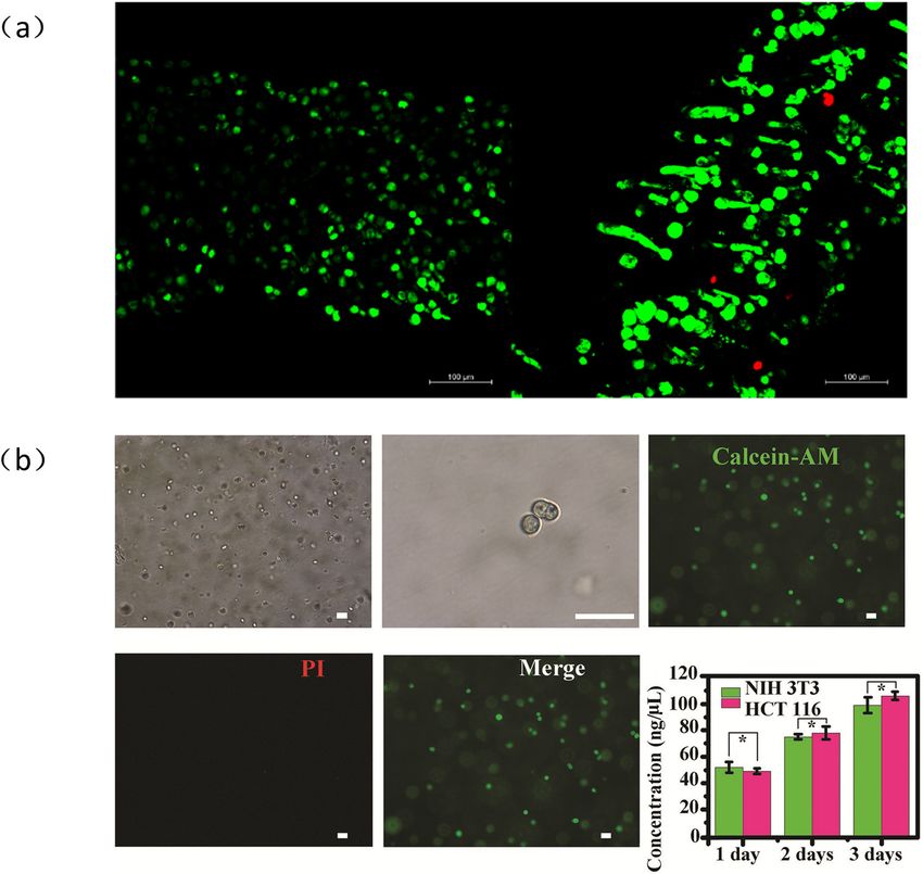
Electrohydrodynamic jet printing 1055 Figure 5: (a) Cone and jet length change graph for different voltages, nozzle sizes and flow rates. (b) Line images of different nozzle to substrate distances. Reproduced from ref. [79] with permission from American Institute of Physics. Under strong electric field conditions, the distance between multilevel voltage is composed of a lower limit voltage Va, the nozzle and the substrate is more likely to change in these an intermediate voltage Vb, and an upper limit voltage process conditions, and the ejection frequency will change Vc for stable cone pulse injection. They have the same significantly, resulting in inconsistent gaps between the frequency but different duty ratios. Compared with the print droplets. Natural pulse jetting is not suitable for square wave pulse voltage, the multistep pulse voltage printing patterns with regular droplet gaps and consistent has an intermediate voltage, which avoids the meniscus droplet sizes [81]. An E-jet printing system driven by pulse disturbance and ejection instability caused by the voltage was proposed by researchers [81–84] to overcome sudden application of high pulses. The multilevel vol- these limitations and realize the controllability of jetting. The tage amplitude and frequency have an effect on the dro- controllability of the printing speed is related to the pulse plet diameter. The droplet size obtained at a frequency voltage frequency. As shown in Figure 6(a) [82], the droplet of 325 Hz is approximately 40 μm. Due to the limitation generation frequency is almost the same as the pulse voltage of lower pulsation frequency [82,83,85], a high-speed frequency, and there is a one-to-one correspondence on-demand electro-injection method using pulsed DC vol- between the two. The pulse duration is less than the Taylor tage signals is proposed [81]. High-pressure jet printing cone formation time, and ejection does not occur. Therefore, has limitations for droplets with the same size, and low- the limiting frequency of droplet generation is determined by pressure E-jet printing has a slow printing speed. This the formation time of the Taylor cone. By adjusting different method superimposes a high-voltage pulse to eject dro- voltage frequencies, periodic pulse cone jets produce uni- plets on the basis of the reference voltage. The choice of formly arranged droplet arrays with a size controlled the reference voltage is critical, but it must be sufficient between 95 and 210 μm [82]. As shown in Figure 6(b) [82], to form and maintain the Taylor cone. The pulse E-jet the droplet size decreases with the increase of the pulse printing achieves a printing speed of 1 kHz. Independent voltage frequency. Rahman et al. [85] proposed an on-demand control of droplet size and droplet spacing is achieved E-jet printing technology using multilevel pulse voltage. The by regulating the pulse duration and the time interval
1056 Shuxiang Cai et al. Figure 6: (a) Graph of the relationship between droplet deposition frequency and pulse voltage frequency. (b) From top to bottom, from left to right, droplet deposition patterns with pulse voltage frequencies of 2.5, 7.5, 15, and 25 Hz. Reproduced from ref. [82] with permission from Elsevier Ltd. (c) The effect of voltage amplitude on injection mode. (d) The effect of pulse duration on injection pattern. (e) The state diagram of the injection mode based on the dimensionless duration and voltage. Reproduced from ref. [84] with permission from Elsevier Ltd. (f) Typical AC pulse voltage waveform diagram for E-jet printing. (g) The influence of AC pulse frequency, duty cycle, and voltage on droplet size. Reproduced from ref. [92] with permission from Elsevier. between two consecutive pulses. The droplet size is as applied voltage, flow rate, surface wettability, and fre- achieved by repeated adjustments of experimental parameters. quency. However, repeated experiments require a lot of The dimensional controllability depends on parameters such time and cost. Park et al. [86] proposed two mathematical
Electrohydrodynamic jet printing 1057
models to predict the size of points and lines. For a pattern shows the experimental results of adjusting the three para-
with a certain size, according to the relationship between the meters to print droplets. Low-frequency pulses, large duty
size and the various process parameters in the proposed cycles, and high voltage amplitudes produce large droplets.
mathematical model, the required experimental conditions Qin et al. [93] achieved 5.9 μm single-layer silver trace
can be obtained, such as flow rate, frequency, duty cycle, printing under the conditions of applying an AC pulse vol-
and stage speed. When the applied voltage amplitude and tage of 400 V, a frequency of 1,000 Hz, and a duty cycle of
pulse duration are changed, the ejection mode of the dro- 10%. The silver traces with an average line width of 13.1 μm
plets is significantly different. Lee et al. [84] studied the were printed by stacking layers of droplets layer by layer.
ejection mode of droplets under different parameters and
the pulse voltage amplitude and duration increase respec-
tively, as shown in Figure 6(c) and (d) [84]. It is determined
that the best pulse injection mode can be achieved when the 3.2 Nozzle design
duration is 2 ms and the voltage is between 8.7 and 8.8 kV.
Finally, a dimensionless graph of pulse duration and ampli- As an important part of the E-jet printing system, the
tude is drawn according to the data. As shown in Figure 6(e) nozzle is not only the outlet of the liquid jet but also
[84], the ranges of the four jet modes of pulsation mode, considered as an electrode. The size and structure of
spindle mode, jet mode, and spray mode are determined. the nozzle is one of the main factors that affect the reso-
Another challenge of E-jet printing based on the tra- lution of the droplets. To obtain a stable jet and higher
ditional DC voltage is that due to the existence of residual resolution, optimal design of the nozzle is necessary
charges of the droplets, the distribution of the electro- [94–97]. Kim et al. [98] compared the effects of two dif-
static field and subsequent changes in the printing beha- ferent shapes of jetting needles on the resolution of
vior are caused. Especially on highly insulated substrates, printed patterns. As shown in Figure 7(a) [98], a flat
the charge decay rate is very slow. When the droplets are needle with an inner diameter of 100 μm and a hypo-
sprayed on the insulating substrate, the charge will be dermic needle are used. The hypodermic needle is more
stored for a long time, causing the Coulomb repulsion hydrophilic after being irradiated with ultraviolet rays.
between the droplets on the substrate and the spray jet, Compared with a flat needle that produces a large meniscus,
which will cause the jet path to change [87–89]. The resi- the meniscus formed at the end of a hypodermic needle is
dual charge makes E-jet printing a challenge for printing much smaller. Figure 7(b) [98] shows that the flat needle
high-resolution continuous structures. To minimize the has a line width of 59 μm, which is about 59% of the
effect of residual charge, AC pulse voltage is used in the needle diameter, while the line width of the hypodermic
E-jet printing process [90–92]. Park and Hwang [90] used needle reaches 0.7 μm, which is only less than 1% of
AC-based jet printing for the first time to prepare a silver the needle diameter. Kim et al. [99] developed a capillary
grid network on a polyethylene terephthalate substrate. nozzle with a nonconductive tip. Compared with common
Using sinusoidal AC pulse voltage to drive the jet, each nozzles, a nonconductive tip nozzle requires a smaller vol-
positive and negative pulse will produce one jet, and the tage value to obtain a stable cone jet, and a pattern size of
positive and negative charges will be jetted alternately, so 30–62 μm can be obtained. The nonconductive tip will help
the charged droplets are neutralized and will not cause the reduce the set voltage by reducing the backflow near the tip
droplets and jets to repel. Under the conditions of a fixed of the liquid flow, thereby helping to form a stable jet.
flow rate of 0.1 μL/min, a voltage with a peak-to-peak Recently, a novel nozzle tip-assisted E-jet printing method
value of 1.4 kV and a frequency of 2 kHz, the speed of was proposed, as shown in Figure 7(c) [100]. This method
the translation stage was adjusted to finally obtain a silver inserts a tip with a diameter of 20 μm and a height of 0.2 mm
grid network with a line width of 13 μm and a line spacing into a nozzle with an inner diameter of 80 μm. The electric
of 250 μm. Wei et al. [92] proposed a method of using AC field intensity at the apex of the tip assist mode can reach
pulse voltage to achieve continuous printing on highly insu- 7.1 × 10⁶ V/m. Moreover, the tip-assisted E-jet printing
lating substrates. The AC pulse waveform diagram is shown printed an array of droplets with a size of 2.3 μm, and
in Figure 6(f) [92]. By adjusting the three process parameters, compared with no tip-assisted, the printing resolution
pulse frequency, pulse voltage amplitude, and duty cycle, was increased by nearly five times.
independent control of droplet size and printing frequency However, in the previous printing system, the ground
is achieved. Among them, the pulse frequency is used to electrode is located below the substrate. If the distance
control the printing frequency, and the voltage amplitude between the nozzle and the substrate is reduced, the
and duty cycle determine the droplet size. Figure 6(g) [92] electric field will be distorted, causing the printing1058 Shuxiang Cai et al. Figure 7: (a) Schematic diagram of the flat exit needle and hypodermic needle. (b) From left to right, the line width and shape changes of flat needles and hypodermic needles with increasing voltage. Reproduced from ref. [98] with permission from American Institute of Physics. (c) Tip-assisted E-jet printing system. Inkjet printing, E-jet printing, and tip-assisted E-jet printing nozzle tip jet comparison chart. Reproduced from ref. [100] with permission from Elsevier BV. (d) Schematic diagram of a printing device with metal ring electrodes. Reproduced from ref. [104] with permission from Elsevier. (e) Double conductive layer electric field forming print head and electric field line distribution. Reproduced from ref. [105] with permission from American Institute of Physics.
Electrohydrodynamic jet printing 1059
process to be unstable. Therefore, the distance between linear nozzle array to reduce crosstalk, as shown in
the nozzle and the substrate must be kept within a certain Figure 8(b) [114]. When the nozzle pitch is 3 and 5 mm,
limit, which greatly limits the uniform printing on uneven compared with the linear array, the offset of the meniscus
and nonconductive surfaces. This limitation can be solved of the triangular array from the nozzle center, that is, the
by designing a new type of print head in which the ground spray angle, is reduced by about 30 and 60%. Parallel
electrode is integrated into the print head [101–103]. As injection of nozzles can greatly improve the efficiency of
shown in Figure 7(d) [104], the printing system integrated patterning. For realization of separate control between dif-
with the nozzle and the metal ring extraction electrode is ferent nozzles, Lee et al. [106] controlled three injection
used to study the droplet generation characteristics of pumps to realize the independent control of a single
organic solvents with and without triglyceride oil [104]. nozzle. Using the clever mechanical design, Sutanto et al.
An innovative nozzle design that integrates the nozzle [115] designed a rotating print head to switch between
and the ground electrode is proposed to solve the problem active and inactive nozzles. Each nozzle is fed with dif-
of printing on uneven surfaces [105]. As shown in Figure 7(e) ferent ink materials, and the size of the droplets can
[105], the field shaping design of the double-layer conduc- reach the micron level, which can not only print with
tive layer separated by dielectric materials is adopted. multiple nozzles but also allows multimaterial printing.
The nozzle tip and the top conductive plate are connected In multinozzle E-jet printing, it is critical to improve the
to a positive voltage, and the bottom conductive plate is controllability of printing and to achieve the consistency of
grounded. Finally, droplets with a resolution of less than individual jets, jet sizes, and positions of each nozzle. For
10 μm are obtained on uneven surfaces. Han and Dong [73] the purpose of improving controllability, a multilevel vol-
designed an integrated ring extractor as a ground elec- tage, multiparallel nozzle addressable E-jet printing system
trode instead of a planar ground electrode to overcome is designed [116]. The print head is composed of a nozzle
the limitation of the height of the support in the 3D struc- layer and an extractor layer. The conductive ring of the
ture printing process. The diameter of the ring extractor is extraction layer can control each nozzle individually, as
4 mm and the distance from the nozzle is set to 300 μm. shown in Figure 8(c) [116]. By controlling the electric
The 3D structure of polycaprolactol with a height of about potential of the noninjecting conductive ring, researchers
500 μm was successfully prepared by using the designed could reduce the interference of the electric field and
nozzle ring. enhance the electric field distribution of the injection
The low production rate of single-nozzle hinders the nozzle. Then, a combination of one, two, and three
application of E-jet printing. Therefore, to improve pro- injection nozzles is realized on the hydrophobic silicon
duction efficiency, nozzle design has attracted widespread wafer, and a droplet array with good size and position
attention, and various nozzle design studies have emerged, consistency is obtained, as shown in Figure 8(d) [116].
such as multinozzles [37,106,107], multihole nozzles [97],
and coaxial nozzles [108–110]. Although multiple nozzles
can effectively solve the problem of low throughput, the
repulsion between adjacent nozzles will cause the meniscus 3.3 Ink characteristics
at the nozzle to deflect outward, which is called end effect,
as shown in Figure 8(a) [111]. The asymmetric electric The ink is a hybrid material composed of functional mate-
field is the main cause of the end effect. At the same time, rials and polymers, which plays a vital role in the jetting
the reduction in the spacing between the nozzles leads to process. The study of ink characteristics (surface tension
crosstalk between adjacent jets, which is a factor that aggra- [61], density [117], viscosity, and conductivity [49,50])
vates the end effect [112]. Another important factor is the helps to better understand the jetting process. Among
use of metal nozzles, which enhance the repulsive force them, the printing jet volume increases with the increase
between adjacent nozzles. Therefore, under the perplexity of viscosity and decreases with the increase of conduc-
of these factors, research on the crosstalk problem of multi- tivity. A large conductivity corresponds to a small shear
nozzle E-jet printing has appeared. A multinozzle made of stress acceleration, and a smaller ejection volume is
dielectric materials is used in the E-jet printing process. The achieved. Therefore, the conductivity increases, the dro-
distance between adjacent nozzles of 3 mm has been deter- plet diameter and the distance between adjacent droplets
mined through testing, which minimizes the crosstalk are reduced [118]. Kwon et al. [119] showed that drop-on-
between adjacent jets [113]. Choi et al. [114] used three demand inkjet printing is a function of viscosity, conduc-
independent ink supply channels and voltage sources tivity, and surface tension, and to better characterize
and used a triangular nozzle array instead of a traditional the performance of E-jet printing, especially the droplet1060 Shuxiang Cai et al. Figure 8: (a) End effect diagram. Reproduced from ref. [111] with permission from Elsevier. (b) Schematic diagram of linear and triangular array multinozzle print heads. Reproduced from ref. [114] with permission from Elsevier. (c) Schematic diagram of addressable E-jet printing with multilevel voltage parallel nozzles. (d) The array of droplets obtained by printing with one, two, and three nozzles. Reproduced from ref. [116] with permission from American Institute of Physics. ejection frequency, a dimensionless universal coefficient contact angle, while a medium particle size has a higher containing the aforementioned three ink properties is initial impact velocity. defined. The pulse duration increases with increasing The core principle of E-jet printing is the formation of viscosity and decreases with increasing conductivity Taylor cone jets. Bae et al. [121] applied the same process and surface tension. Larger particles in the ink will lead parameters to seven solutions with different surface ten- to the formation of satellite droplets, which will affect the sions. The results show that the ink surface tension affects resolution and the quality of the printing. Increasing the the jet pattern of E-jet printing. At the same time, under the viscosity can effectively reduce the number of satellite same electrostatic field, compared with polystyrene, poly- droplets [50]. The size of the metal particles in the methyl methacrylate with higher conductivity has faster printing ink affects the ink configuration, which in turn charge convection, so the cone-shaped phase transition affects the droplet behavior. Therefore, Huang et al. [120] is faster and the conductivity is related to the change of used inks with three different particle configurations of the meniscus structure. As a key material property, ink small particle size, medium particle size, and large par- viscoelasticity affects jet ejection. Yu et al. [122] designed ticle size to study the effects on droplet wetting diameter, two independent models of elasticity and viscosity. The height, contact angle, and impact velocity. The data show dimensionless numbers ξ and χ are used to represent the that under the action of an electric field, a large particle elasticity and the viscosity of the ink, and a dimensionless size brings a small droplet wetting diameter and a small operating window diagram is drawn. Figure 9(a) [122]
Electrohydrodynamic jet printing 1061
Figure 9: (a) From top to bottom, from left to right, the jet windows of six PEO solutions with different molecular weights: M03, M06, M10,
M20, M40, and M50. For example, M10 represents a PEO solution with a molecular weight of 1.0 × 10⁶ g/mol. (b) From top to bottom, from
left to right, the jet window diagrams of six PEO solutions with different viscosities: C18, C24, C30, C38, C42, C52. For example, C18 means
0.18 wt% PEO solution. Reproduced from ref. [122] with permission from Elsevier BV. (c) Comparison of the jet modes of Newtonian fluid and
viscoelastic fluid. Reproduced from ref. [123] with permission from American Institute of Physics.
shows that the increase in elasticity expands the voltage polyethylene oxide/water (high conductivity and high vis-
range of the Taylor cone jet. The study found that although coelasticity) were chosen to study the starting position of
elasticity delays the formation of the cone jet, it improves the unstable whip motion [124]. The starting position of
the stability of the jet cone shape. As shown in Figure 9(b) the whip motion decreases linearly with the electric field.
[122], when χ > 1 and χ < 1, the increase in viscosity In contrast, the polyethylene oxide/water solution is sig-
broadens the voltage and the flow range of the Taylor nificantly affected by the electric field due to its high con-
cone jet, and the viscosity can be used to stabilize the ductivity whip motion. Therefore, highly conductive inks
Taylor cone jet. At the same time, the viscoelasticity of are not suitable for stable E-jet printing.
the ink leads to changes in the fluid dynamics behavior,
resulting in a new E-jet printing mode that is different from
Newtonian fluids, as shown in Figure 9(c) [123]. In the
dripping mode, since the droplets exhibit strong elasticity,
4 Application of E-jet printing
the droplets cannot immediately leave the nozzle and form
filaments until they break. The second mode is the beaded 4.1 Electronic devices
mode, which can be observed only in viscoelastic fluids.
The increase of the electric field results in the cone jet E-jet printing technology, as a mask-free additive manu-
mode and the rod-shaped jet mode with a thinner jet. facturing process, can print various functional materials
When the voltage reaches the unstable threshold, there onto flexible substrates, making printing technology unique
is no branch at the lower end of the unstable jet because in the rapid preparation of electronic devices effect.
the viscoelasticity stabilizes the jet. As the concentration Although inkjet printing has become popular in printed
of the solution increases, the rod-shaped jet mode is stable electronic products, the rapid development of electronic
in a wider range of the electrocapillary tube. Viscoelasti- products and the continuous improvement of resolution
city and conductivity are one of the reasons for the requirements make inkjet printing unable to meet the
instability of the cone jet. The Coulomb repulsion between requirements. As a high-resolution printing technology,
the charges on the surface causes the instability of the E-jet printing plays an important role in the preparation
jet, which depends on the electric field. Based on viscoe- of electronic devices. The application of E-jet printing in
lasticity and conductivity, polyisobutylene/polybutene the manufacture of flexible electronic devices (such as
(low conductivity and high viscoelasticity), silver nanopar- conductive electrodes, field-effect transistors, and sensors)
ticle ink (high conductivity and low viscoelasticity), and is discussed (Table 2).1062 Shuxiang Cai et al.
Table 2: Application of E-jet printing
Application of E-jet Advantages Application examples
printing
Electronic devices
Conductive • Maskless • Printed conductive silver traces with a size of 35 μm,
electrodes calculated resistivity is 3.9 × 10⁻⁸ Ω/m
• Low-cost rapid production • A silver grid/graphene hybrid transparent conductive
electrode with a resistivity of about 25 μΩ/cm was
fabricated
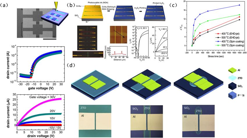
Transistor • A wide range of functional materials • ZnO thin film transistors (TFTs)
• Suitable for unconventional substrates such • M-PEDOT:PSS electrode transistor
as/stretchable substrates and uneven curved
surfaces
Sensors • High resolution • Resistive temperature sensor with resistivity of
23.35 μΩ cm was fabricated
• Humidity sensor with high sensitivity (85 kΩ/%RH) and
responsiveness (0–80% RH) was fabricated
Bioprinting
Cells and • High resolution • Pattern the fibrin protein
extracellular matrix
Tissue engineering • Fabricating DNA and protein microarrays • Living cells printing
scaffold • High cell survival rate • E-jet printing is widely used in the construction of 3D
scaffolds for specific tissue types, such as cartilage,
tendon, bone, and heart
4.1.1 Printing patterned conductive electrodes conductive materials used for the electrodes, thereby rea-
lizing high-resolution electrode patterns. Wang et al.
In the manufacture of electronic devices, the clear pat- [125] achieved a printing distance of 50 μm through E-
terned electrode lines is an important part of the realiza- jet printing and printed conductive silver traces with a
tion of high-performance circuits, and patterned conduc- size of 35 μm. The measured and calculated resistivity is
tive electrodes are crucial in achieving high integration of 3.9 × 10⁻⁸ Ω/m. Figure 10(a) [125] shows the microstruc-
electronic devices. E-jet printing can directly print the ture of the center and the edge of the printed stripes.
Figure 10: (a) Scanning electron microscopy image of printed silver traces on a silicon substrate after curing and cross-sectional profile
measured by atomic force microscope. Reproduced from ref. [125] with permission from American Institute of Physics. (b) E-jet printed
square silver grid electrode and gold grid electrode. Reproduced from ref. [132] with permission from Wiley-VCH Verlag.You can also read