The Importance of a Longer VID for AR HUDs - Texas ...
←
→
Page content transcription
If your browser does not render page correctly, please read the page content below
www.ti.com Technical White Paper
Technical White Paper
The Importance of a Longer VID for AR HUDs
Technical White Paper
Augmented-reality head-up displays (AR HUDs) have the potential to further enhance user experience and
safety while driving. Because AR HUDs combine a virtual image (AR information) with the real world, they need
a wide field of view (FOV) and a long virtual image distance (VID).
A longer VID can result in a better driving experience and a lower cost AR HUD system. In this white paper, we
discuss physiological distance cues to explain why human eyes experience less fatigue when looking at objects
farther away, how a longer VID can reduce the parallax effect, and how a longer VID can enable designers to
save costs by eliminating eye-tracking systems and wedge films.
Physiological distance cues
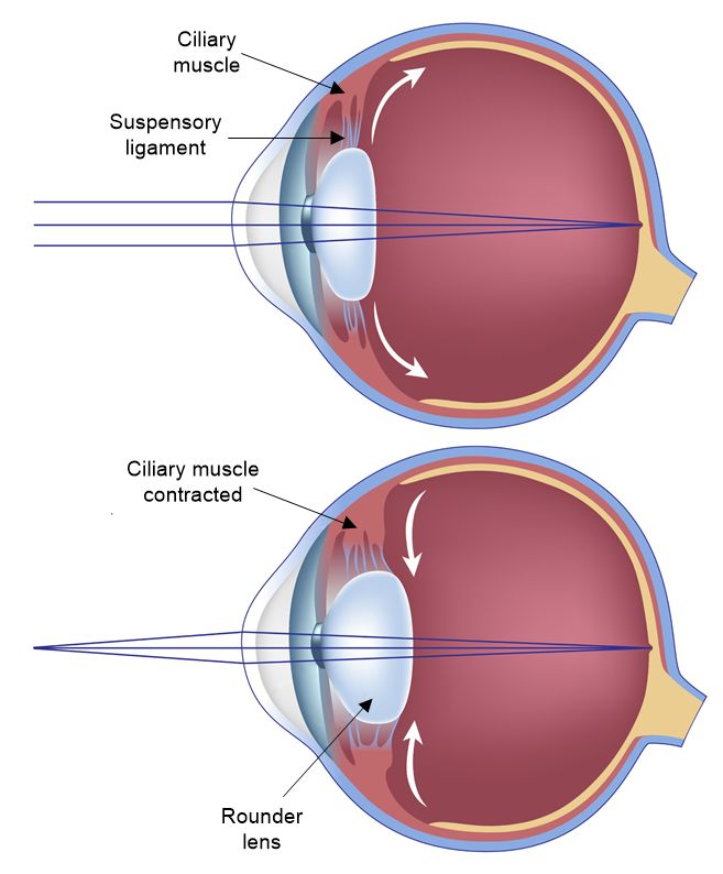
Eye accommodation is the process where the human eye adjusts the focal length of its lens to have a focused
image of the object at the retina surface depending on the distance of the object. The ciliary muscle and
suspensory ligament need to contract or relax the lens of the eyes to adjust the focal length, as shown in Figure
1-1. To see an object that is close by, the ciliary muscle needs to contract to make the lens rounder, giving the
eye a shorter focal length. To see an object farther away, the lens needs be flatter to have a longer focal length.
Figure 1-1. Eye Accomodation
DLPA117A – OCTOBER 2020 – REVISED FEBRUARY 2021 The Importance of a Longer VID for AR HUDs 1
Submit Document Feedback
Copyright © 2021 Texas Instruments Incorporated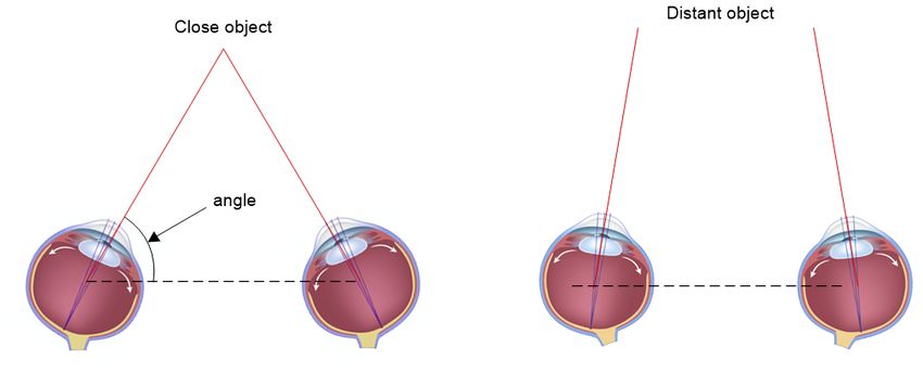
Technical White Paper                                                                                                               www.ti.com

Figure 1-2 graphs the change in focal length versus the distance of an object.

       Figure 1-2. Lens of Human Eyes Focal Length in Centimeters vs. the Object Distance in Meters

As Figure 1-2 illustrates, the eyes will be relaxed (and thus less fatigued) when the object distance is 6 m or
more. In normal driving conditions, a driver’s eyes focus at distances much farther away than 6 m. If the HUD
information is located at a shorter distance (such as 2 m in traditional HUDs), the eyes need to make
adjustments to focus on HUD information and real-world objects. Such adjustments can lead to eye fatigue and
a poor driving experience.
Eye convergence is the act of rotating the eyes to focus on an object, as shown in Figure 1-3. Objects that are
closer require the eyes to rotate more inward, also causing eye fatigue. When focusing on objects that are
farther away, the eyes remain more parallel and require less muscle strain to align with the object. The farther
the object distance, the less muscle movement required.

                                                     Figure 1-3. Eye Convergence

2     The Importance of a Longer VID for AR HUDs                                              DLPA117A – OCTOBER 2020 – REVISED FEBRUARY 2021
                                                                                                                        Submit Document Feedback
                                                   Copyright © 2021 Texas Instruments Incorporated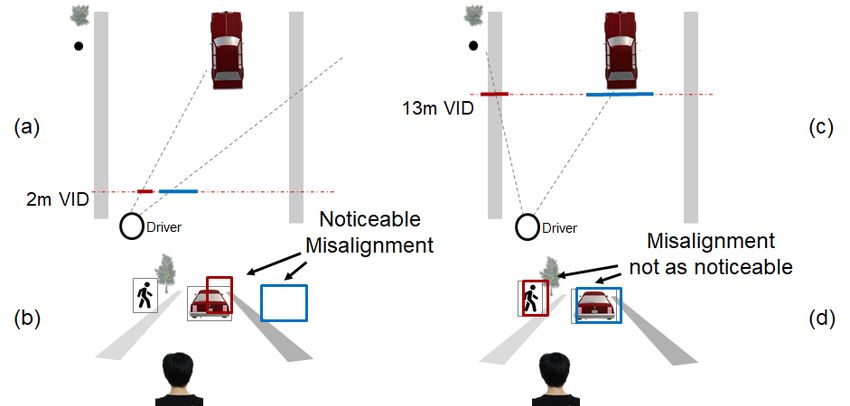
www.ti.com                                                                                                            Technical White Paper

Figure 1-4 graphs the angle of eye rotation versus the object distance.

                   Figure 1-4. Eye Rotation Angle in Degrees vs. the Object Distance in Meters

The distance of an object also affects the fusion of AR information to the real world. When the VID is greater
than 6 m, the eyes are less sensitive to discrepancies in physiological distance cues and will perceive that the
AR information is more strongly fused with the real world. Thus, a VID longer than 6 m is necessary for a good
user experience.
The Parallax Effect
Parallax is a displacement or difference in the apparent position of an object viewed along two different lines of
sight. Parallax is the change of alignment of the virtual image and the real-world object when the human eye
changes position.
Figure 1-5 shows two examples where the virtual images and the real-world objects are perfectly aligned while
the driver’s eyes are in the intended position. The virtual images are located at 2 m and 13 m. Figure 1-5 (a) and
(c) are perspectives from above showing the locations of the virtual images and real-world objects. Figure 1-5 (b)
and (d) show the driver’s perspective. The red and blue rectangular blocks in both Figure 1-5 (b) and (d) are well
aligned with the pedestrian and the car in front of the driver even though the VIDs are very different.

DLPA117A – OCTOBER 2020 – REVISED FEBRUARY 2021                                              The Importance of a Longer VID for AR HUDs   3
Submit Document Feedback
                                           Copyright © 2021 Texas Instruments Incorporated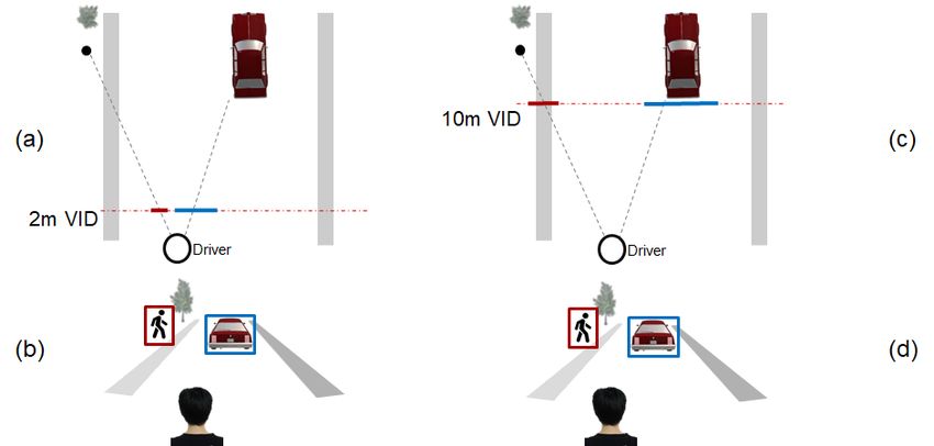
Technical White Paper                                                                                                               www.ti.com

                            Figure 1-5. Alignment of Virtual Images and Real-World Objects

Figure 1-6 illustrates what happens when the driver moves their head slightly to the left. The red and blue
rectangles will also move because of the parallax effect, resulting in a misalignment of the virtual images and
real-world objects. However, there is a large difference in the degree of misalignment between the 2m and 13m
VID cases. In the 2-m VID case, depicted in Figure 1-6 (b), the red and blue rectangles have moved completely
out of the intended alignment with the pedestrian and car due to the short VID. The misalignment in the 13-m
VID case is much smaller and not as noticeable due to the longer VID, as depicted in Figure 1-6 (d).

     Figure 1-6. Alignment of Virtual Image and Real-World Objects when the Driver Moves Their Head
                                             Slightly to the Left

4     The Importance of a Longer VID for AR HUDs                                              DLPA117A – OCTOBER 2020 – REVISED FEBRUARY 2021
                                                                                                                        Submit Document Feedback
                                                   Copyright © 2021 Texas Instruments Incorporated
www.ti.com Technical White Paper
It is possible to calculate this misalignment. Figure 1-7 shows the magnitude of misalignment of the virtual image
and real-world object, where D is the distance of the real-world object, Δeye is the change in eye position and
∆image is the change of the virtual image position at the target distance, D. For a 2-m VID, if the real-world
object is at a distance of 25 m (D = 25 m) and the eye position changes by 10 cm, the virtual image position will
move by 1.2 m, which is significant enough to see an obvious misalignment. For a 13-m VID, the same change
in eye position will result in only a 10-cm change in virtual image position, which is negligible.
Figure 1-7. Misalignment (Δimage) of the Virtual Image and the Real-World Object at Distance D Caused
by Eye Position Change (Δeye). The Misalignment Decreases as the VID Increases
Eye Tracking
Automotive designers often implement eye tracking in order to eliminate the parallax effect for short VID HUD
systems. Such systems, however, can not only increase system costs and R&D effort, but can also result in a
poor user experience given the latency between the head movement and the virtual image adjustment.
Eliminating eye tracking can simplify the graphic rendering of the human machine interface as well as the load
on the graphic processor. A longer VID (10 m to 15 m) reduces the parallax effect and makes it simpler to
maintain the alignment of virtual images to the real world.
Wedge Film
HUD systems with a short VID and standard windshield glass produce a double image caused by reflections
from both the top and the bottom surfaces of the windshield glass. A wedge film in the windshield glass helps
eliminate the double image.
Figure 1-8 illustrates how the windshield glass creates a double image. The light of the HUD image is projected
to the windshield at an angle of to the normal line. The red solid line is the first reflection off the bottom surface.
The refraction light of the image has an angle of and is reflected when reaching the top surface of the
windshield. The red dashed line shows the image caused by the second reflection.
DLPA117A – OCTOBER 2020 – REVISED FEBRUARY 2021 The Importance of a Longer VID for AR HUDs 5
Submit Document Feedback
Copyright © 2021 Texas Instruments IncorporatedTechnical White Paper www.ti.com
Figure 1-8. Illustration of the Double Image Created by the Two Reflections
Equation 1 calculates the displacement, d, of the two images:
d = 2 t ⋅ tan ( β ) ⋅ cos ( α ) (1)
where t is the thickness of the glass
Equation 2 expresses the relationship between α and β:
sin ( α ) = n ⋅ sin ( β ) (2)
where n is the refraction index of glass, which is approximately 1.5
The reflected light typically has a small look-down angle (the angle between the light line and the horizon) such
as 2 degrees, but we will neglect this angle to simplify the calculations. Using = 60 degrees and t = 5.5 mm as an
example, the calculations result in = 35.3 degrees and d = 3.9 mm.
Although the linear displacement of the two images remains constant and independent of the VID, the angular
displacement is dependent on VID. The two images in Figure 1-8 are always 3.9 mm apart from each other,
regardless of the VID. When the two images are close to the driver, the double image is easily distinguishable.
As the two images move further away from the driver – that is, at a longer VID – the double image will be less
distinguishable. As the VID increases, the same 3.9 mm will have less angular displacement.
Converting from linear displacement to angular displacement for the two images, Equation 3 calculates the
displacement angle as:
d
A n g l e = arcsin ( ) (3)
VID
For typical human vision, the angular resolution is 1 arc minute, or one-sixtieth of a degree. Most displays use 60
pixels per degree (ppd) as a criterion for display resolution. When the angle given by Equation 3 is less than
one-sixtieth of a degree, the double image is no longer visible to the driver.
6 The Importance of a Longer VID for AR HUDs DLPA117A – OCTOBER 2020 – REVISED FEBRUARY 2021
Submit Document Feedback
Copyright © 2021 Texas Instruments Incorporatedwww.ti.com Technical White Paper
The displacement angle can also be converted into a number of pixels with Equation 4, assuming that the
resolution is 60 ppd:
d
Number of Pixels = arcsin ( ) ⋅ 60 (4)
VID
Figure 1-9 graphs the relationship between the number of pixels and the VID, where the thickness of the glass (t)
is assumed to be 5.5 mm. When = 60 degrees (or the slope of the windshield is approximately 30 degrees), the
displacement of the double image is 1 pixel (1/60 of a degree) when the VID is 13 m, which is the limit of typical
human vision resolution.
Therefore, when the VID is longer than 13 m, there is no need for a wedge film to remove the double image.
Using a longer VID makes it possible to potentially eliminate the wedge film, reducing system complexity and
cost.
Figure 1-9. The Displacement of the Two Images by Pixel Number when the Resolution is at 60 ppd
Conclusion
A longer VID in an AR HUD system can result in a better user experience and lower system cost. A longer VID
will result in less eye fatigue, a negligible parallax effect when the driver moves their head or eyes, better fusion
between AR information and real-world objects, and the elimination of wedge film and eye-tracking
requirements.
The optimal VID is between 12 m and 15 m. This VID range makes it possible to fuse virtual images with the real
world. The benefit diminishes if the VID increases beyond this recommended range.
A longer VID does negatively impact HUD systems with traditional optical designs, however, by creating a solar
load challenge. The white paper, DLP® Technology: Solar Loading in Augmented Reality Head-Up Display
Systems, has a detailed discussion on solar load challenges in HUD designs. HUDs adopting DLP technology
can tolerate much higher solar loads and enable long VIDs without any thermal issues.
DLPA117A – OCTOBER 2020 – REVISED FEBRUARY 2021 The Importance of a Longer VID for AR HUDs 7
Submit Document Feedback
Copyright © 2021 Texas Instruments IncorporatedIMPORTANT NOTICE AND DISCLAIMER
TI PROVIDES TECHNICAL AND RELIABILITY DATA (INCLUDING DATASHEETS), DESIGN RESOURCES (INCLUDING REFERENCE
DESIGNS), APPLICATION OR OTHER DESIGN ADVICE, WEB TOOLS, SAFETY INFORMATION, AND OTHER RESOURCES “AS IS”
AND WITH ALL FAULTS, AND DISCLAIMS ALL WARRANTIES, EXPRESS AND IMPLIED, INCLUDING WITHOUT LIMITATION ANY
IMPLIED WARRANTIES OF MERCHANTABILITY, FITNESS FOR A PARTICULAR PURPOSE OR NON-INFRINGEMENT OF THIRD
PARTY INTELLECTUAL PROPERTY RIGHTS.
These resources are intended for skilled developers designing with TI products. You are solely responsible for (1) selecting the appropriate
TI products for your application, (2) designing, validating and testing your application, and (3) ensuring your application meets applicable
standards, and any other safety, security, or other requirements. These resources are subject to change without notice. TI grants you
permission to use these resources only for development of an application that uses the TI products described in the resource. Other
reproduction and display of these resources is prohibited. No license is granted to any other TI intellectual property right or to any third party
intellectual property right. TI disclaims responsibility for, and you will fully indemnify TI and its representatives against, any claims, damages,
costs, losses, and liabilities arising out of your use of these resources.
TI’s products are provided subject to TI’s Terms of Sale (https:www.ti.com/legal/termsofsale.html) or other applicable terms available either
on ti.com or provided in conjunction with such TI products. TI’s provision of these resources does not expand or otherwise alter TI’s
applicable warranties or warranty disclaimers for TI products.IMPORTANT NOTICE
Mailing Address: Texas Instruments, Post Office Box 655303, Dallas, Texas 75265
Copyright © 2021, Texas Instruments IncorporatedYou can also read