EtherNet/IP to Modbus RTU Gateway - Application Note
←
→
Page content transcription
If your browser does not render page correctly, please read the page content below
EtherNet/IP to Modbus RTU
                                                                                    May 18, 2020

                                  Application Note
      EtherNet/IP to Modbus RTU Gateway
OVERVIEW
Industrial communication protocols are used to establish a client-server or master-slave
communication between industrial automation devices, such as Programmable Logic
Controllers (PLC), Remote Terminal Unit (RTU), Distributed Control Systems (DCS) and Human
Machine Interfaces (HMI). For industrial automated applications, there are many industrial
Ethernet communication protocols, such as Modbus TCP, EtherNet/IP and PROFINET.

As new protocols are created, it becomes more and more difficult for various devices to
communicate with each other and form a cohesive system. The SignalFire Gateway natively
communicates over Modbus RTU or Modbus TCP but may need to be converted to another
protocol to communicate with a master device.

One protocol that is becoming more common is EtherNet/IP (Ethernet Industrial Protocol).
Industrial controls and instrumentation have long lagged behind other fields in wide-area
network capabilities, and EtherNet/IP aims to allow easy movement between traditional
communication and the internet. While the SignalFire Gateway does not have built-in
EtherNet/IP, it can communicate over EtherNet/IP using a Phoenix Contact EIP/Modbus
converter with very minimal setup.

This application note assumes familiarity with Rockwell Studio 5000, Allen-Bradley PLC’s, and
the SignalFire system, and serves to help create smooth communication, facilitating cutting
edge remote instrumentation and controls capabilities between these systems. For more
information on the SignalFire equipment, its setup, and various features, please visit our
website www.signal-fire.com and call us any time 8AM-5PM Monday through Friday at 978-
212-2868 for assistance from an engineer.

The overall steps for those familiar with each system overall are as follows:
   1) Set up the SignalFire network and its Remapping
   2) Configure the Phoenix Contact EIP/Modbus converter to pull the needed registers from
       the SF Gateway
   3) Create the data tag arrays in the Rockwell Studio 5000 to organize the data

                                                                                                   1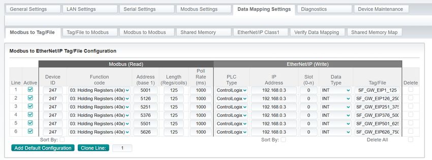
EtherNet/IP to Modbus RTU
                                                                                     May 18, 2020

EQUIPMENT USED
-   SignalFire Gateway
-   Rockwell/Allen-Bradley 5380 CompactLogix Controller (5069-L340ERM)
-   Phoenix Contact Ethernet/IP Gateway (EIP GW) (P/N: GW EIP/MODBUS 1E/1DB9)
-   Ethernet Switch

WIRING DIAGRAM

                                       ETHERNET SWITCH

                                                               RS-485 A

                                       PHOENIX CONTACT                          SIGNALFIRE
    ALLEN-BRADLEY                       ALLEN-BRADLEY
                                         ETHERNET/IP                             GATEWAY

                                                               RS-485 B
                                             Figure 1

NOTE The ‘A’ and ‘B’ lines need to be swapped between the Phoenix Contact and Gateway. All
devices in this system can take 24VDC for power.
Depending on your network settings, you may have to change your computer’s IP address. In
the setup used for this application note, the Allen-Bradley PLC had an IP of 192.168.0.3, and the
Phoenix Contact had an IP of 192.168.0.31. The computer had its IP settings changed as follows:

                                             Figure 2

                                                                                                    2
EtherNet/IP to Modbus RTU
May 18, 2020
If you connect the SignalFire Gateway to the network switch through a SignalFire Ethernet
Interface Module, you may connect their RS-232 lines (Yellow and Orange) together, but the
RS-485 lines (Brown and Green) should only be connected to the Phoenix Contact EIP/Modbus.
PROCEDURE
SignalFire Slave Register Remapping
Set up the SignalFire network with its nodes as needed. Keep in mind that every SignalFire node
needs to have the same Radio Network, Radio Network Group, and Encryption Key as the
Gateway to connect to it but must each have a unique Slave ID. Refer to either the Gateway
manual or the Quick Startup Guide for putting together a SignalFire network. Figure 3 shows a
Gateway with two Pressure Scouts connected to it.
Figure 3
Each node that checks into the Gateway will have its own Slave ID, cache its registers at the
Gateway, and can be addressed individually. While this is a valid way to pull information from
the network, it is far more efficient and flexible to use the Gateway’s Slave Register Remapping
system. That allows the user to access only the registers needed and pull them all from the
Gateway’s Slave ID (default 247).
Go to Settings → Slave Register Remapping, and type in the Slave ID’s and addresses of the
registers needed in the Allen-Bradley PLC. Click “Write to GW” to set them in memory. In the
example below, the PSI and scaled pressure readings of both Pressure Scouts are remapped in
floating point registers.
3EtherNet/IP to Modbus RTU
May 18, 2020
Figure 4
If using a mix of floating-point and integer values, make sure to enter both addresses of a
floating-point register as separate lines. It’s best to map all the floating-point registers in one
section and all the integer values in another section. The Phoenix Contact EIP/Modbus cannot
mix and match floats and integers in a single poll, as seen later on in the procedure.
Alternatively, you may check off the “Remap All Registers to Data Type Float”. In this mode the
SignalFire Gateway will convert all remapped registers to floats so all data can be polled using a
single datatype. Keep in mind that if you then enter integers, every other address will be
skipped, as shown in Figure 5.
Figure 5
4EtherNet/IP to Modbus RTU
May 18, 2020
Phoenix Contact EIP/Modbus Gateway Configuration
Power up the Phoenix Contact EIP/Modbus Gateway (EIP GW), wire its DB9 port to the Modbus
RTU network, and its Ethernet port to an Ethernet switch as shown in Figure 1. The EIP GW’s
“A” should connect to the SignalFire Gateway’s “B”, and vice versa.
Open a web browser, and type in the IP address of the EIP GW in the address bar. A window will
pop up to enter the default username (Admin) and password (admin). Go to the Serial Settings
tab and confirm the Serial Port Configuration appears as it does in Figure 6.
Figure 6
The EIP GW communicates with RS-485 to the SignalFire
Gateway, so its communication parameters need to match.
Make sure the Baud Rate, and Data/Parity/Stop bits of the
Phoenix EIP (seen above) match those same parameters for the
SignalFire Gateway; the Gateway’s settings can be found in the
bottom left of its ToolKit configuration window. The default
setting is 9600-8N1.
Figure 7
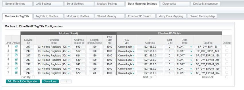
Next, in the EIP GW’s browser page, select the “Data Mapping Settings” tab then select the
“Modbus to Tag/File” as shown in Figure 8.
The left side of the panel is the entry for which registers to read off the SignalFire Gateway.
Specify the Slave ID (247 for the Gateway), the function code (03 Holding Registers), starting
address, and number of consecutive addresses to read from that starting address.
There is an offset of 1, so a starting address of 5001 in the Ethernet/IP will actually correspond
to an address of 5000. Modbus protocol also has a 125-register limit for a single read, so break
up reads into smaller sections if more than 125 registers are needed from any one Slave ID.
5EtherNet/IP to Modbus RTU
May 18, 2020
Figure 8
The left side shows SignalFire registers; the right side is for corresponding data array tags on the
Allen-Bradley PLC. The remapped registers in Figure 8 are all integers, polled by the Allen-
Bradley PLC into 16-bit INT register tags through the EIP GW.
Floating point values can also be read into the Allen-Bradley PLC. It will still be same number of
16-bit registers (every floating point register is two 16-bit registers), so there will still be the
same limit on the number of registers read from the Gateway in a given read, but it will
correspond to half as many data tags in the PLC. In the screenshot below, 120 registers from
the SignalFire Gateway are placed into 60 tags. In the Rockwell Studio 5000, floating point
values are displayed as REAL data type.
Figure 9
6EtherNet/IP to Modbus RTU
May 18, 2020
Rockwell/Allen-Bradley Studio 5000 Configuration
Configure Studio 5000 to your Logix controller program to address the IP address of the EIP
GW. To place the EtherNet/IP ControlLogix tags within a Studio 5000 Logix controller program,
go to the Controller Tag database within your Logix program. Select the “Edit Tags” tag and
create the six 125 tag arrays with the exact description and length of each of array configured
within the EIP GW Modbus to EtherNet/IP Tag/File configuration. Make sure to select
Read/Write Access for each array entry.
Figure 10
The “Tag/File” column in the EIP GW’s Modbus map (left) should match the Controller Tags
names in Rockwell Studio (right). Once completed, compile, save and download the Logix
program to the PLC, and go online.
The EIP GW will pull registers from the Gateway and place them in the Allen-Bradley PLC’s
registers, as shown in Figure 11. The pressures of both Pressure Scouts, in ‘PSI’ and scaled ‘in.
H2O’, are in their designated tags.
Figure 11
7EtherNet/IP to Modbus RTU
May 18, 2020
Online System Verification and Diagnostics
To confirm active communication, click on the “RS-485 Details” button on the bottom of the
SignalFire Gateway Toolkit window to pull up the Gateways RS-485 transmission log. The log
shows any data coming in and out of its RS-485 line. If everything is working well, there will be
read requests marked ‘SUCCEEDED’ that match the mapped settings in the EIP, shown in Figure
12.
Figure 12
The values in the Studio 5000 Controller Tag arrays should match the values in the SignalFire
Gateway’s slave register remap window, shown side-by-side in Figure 13.
Figure 13
8EtherNet/IP to Modbus RTU
May 18, 2020
The Phoenix Contact EIP GW browser configuration has a Diagnostics tab with options to view
serial statistics and logs. Same as the SignalFire RS-485 Modbus Transmission Log, the Phoenix
Contact has its own transmission log, especially useful for diagnostic. Other Diagnostics tabs are
available for EtherNet/IP communications as shown in Figure 14.
Figure 14
BULK REGISTER LOADING
To load bulk registers files to read from the SignalFire network to an Allen-Bradley Ethernet/IP
Logix PLC through a Phoenix Contact EIP/Modbus converter, follow the steps below for each
device:
1) Phoenix Contact EIP Converter Configuration File: Load a pre-configured file to the
Phoenix Contact EIP/Modbus converter.
a. Download the file “EtherNet/IP Configuration” from our website at
https://signal-fire.com/application-notes/ and unzip it to a folder. Open
“README.txt” for file descriptions and condensed instructions.
b. Open a web browser, and type in the IP address of the EIP GW in the address
bar. A window will pop up to enter the default username (Admin) and password
(admin). Go to the Device Maintenance tab, then Config Files. Browse for the
‘.DC’ file needed from the unzipped folder.
c. Enter in the password “signalfire” and hit Load. The IP address in the config file is
192.168.0.31. You may have to adjust your network settings accordingly.
d. Go to the LAN settings tab and enter the IP address to be used on the network
then Apply Changes.
e. Go to the Data Mappings Settings and enter the Ethernet IP address of the Allen-
Bradley controller for each of the data arrays entries and Apply Changes.
9EtherNet/IP to Modbus RTU
May 18, 2020
2) Rockwell Studio 5000 Program File: Load the data tag arrays in the Rockwell Studio
5000 software program file.
a. Load the Rockwell Studio 5000 program for your Allen-Bradley PLC and open up
the Controller Tags database then select the Edit tab.
b. Go to the Standard Toolbar of the Rockwell Studio 5000 software and select
Tools>Import>Tag and Logic Comments then browse for the appropriate ‘.CSV’
file saved to your computer in the above step.
c. Once completed, compile, save and download the Logix program to the
controller then go online.
3) SignalFire Gateway: Fill out the Remapping data within the gateway of the SignalFire
network using the SignalFire Toolkit as described within the SignalFire Slave Register
Remapping section of this application note.
NOTE: As data is entered and written to the SignalFire Gateway, the data will appear
immediately in the Rockwell Logix Tag database.
REVIEW
SignalFire provides conversion from Modbus RTU to Modbus TCP, but not to EtherNet/IP. A
simple way to convert between the two is the Phoenix Contact EIP/Modbus Gateway. In a
matter of minutes, users can get their SignalFire network data into the system of their choosing
through EtherNet/IP.
Use the SignalFire’s register remapping to make all the relevant node addresses accessible
through the Gateway’s slave ID. Connect the Phoenix Contact EIP/Modbus GW to the network
switch and wire its RS-485 to the SignalFire Gateway (with the polarity switched).
In the Phoenix Contact, match the RS-485 settings, and map the SignalFire registers to Allen-
Bradley data tags.
Finally, set up the data tag arrays in Rockwell Studio 5000. Once downloaded to the Allen-
Bradley PLC, it should see live values from SignalFire through EtherNet/IP.
10You can also read