The JamBerry - A Stand-Alone Device for Networked Music Performance Based on the Raspberry Pi
←
→
Page content transcription
If your browser does not render page correctly, please read the page content below
The JamBerry - A Stand-Alone Device for Networked Music
Performance Based on the Raspberry Pi
Florian Meier Marco Fink and Udo Zölzer
Hamburg University of Technology Dept. of Signal Processing
Schwarzenbergstraße 95 and Communications
21073 Hamburg, Germany, Helmut-Schmidt-University
florian.meier@tuhh.de Holstenhofweg 85,
22043 Hamburg, Germany,
marco.fink@hsu-hh.de
Abstract and simple connection of typical audio hard-
Today’s public Internet availability and capabilities ware and instruments. The Raspberry Pi itself
allow manifold applications in the field of multime- can be described as chip-card-sized single-board
dia that were not possible a few years ago. One computer. It was initiated for educational pur-
emerging application is the so-called Networked Mu- poses and is now widely-used, especially in the
sic Performance, standing for the online, low-latency hardware hobbyist community since it provides
interaction of musicians. This work proposes a various interfaces for all sorts of extensions.
stand-alone device for that specific purpose and is
based on a Raspberry Pi running a Linux-based op-
erating system.
Keywords
Networked Music Performance, Audio over IP,
ALSA, Raspberry Pi
1 Introduction
The ways of today’s online communication are
versatile and rapidly evolving. The trend went
from text-based communication, over audio-
based communication, and finally constituted in Figure 1: The JamBerry Device
multimedia-based communication. One arising
branch of online communication is the so-called The paper is structured as following. An in-
Networked Music Performance (NMP), a spe- troduction into the topic of Audio over IP is
cial application of Audio over IP (AoIP). It al- given in Section 2, including the requirements
lows musicians to interact with each other in and major challenges when building such a sys-
a virtual acoustic space by connecting their in- tem. Section 3 gives a detailed view on the ac-
struments to their computers and a software- tual AoIP software running on the JamBerry.
based link-up. This procedure allows artistic The necessary extensions of the Linux audio
collaborations over long distances without the drivers and the integration in the ALSA frame-
need of traveling and hence, can enrich the life work is depicted in Section 4. The custom hard-
of artists. Instead of increasing the content di- ware extensions to the Raspberry Pi are ex-
mensionality and therefore the data rate, the plained in Section 5. Section 6 highlights the ca-
challenge in AoIP is to fulfill a certain delay pabilities of the JamBerry in the contexts of au-
threshold that still allows musical interaction. dio and network parameters, whereas conclud-
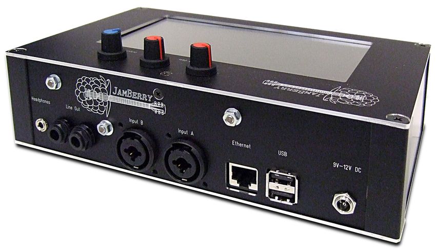
For the purpose of providing an easy-to-use ing thoughts can be found in Section 7.
system realization, an all-in-one device, entitled
the JamBerry, is presented in this work. The 2 Audio over IP
proposed system, as shown in Fig. 1, consists Transmission of Audio over IP-based networks
of the well-known Raspberry Pi [1] and several is nowadays a wide-spread technology with two
custom hardware extensions. These are neces- main applications: Broadcasting audio streams
sary since the Raspberry Pi does not provide and telephony applications. While the first one
high-quality audio output and no audio input at provides no return channel, the second one al-
all. Furthermore, the proposed device includes lows for direct interaction over large distances.
several hardware components allowing a quick Although, the requirements in terms of audioquality and latency for playing live music to- Furthermore, no further signal processing steps,
gether are not fulfilled by current telephony sys- depending on highly-detailed signaled represen-
tems. tations, are involved. To allow the interaction
The massive spreading of broad-band Inter- with several musicians but still stick to the com-
net connections and increase in network reliabil- putational constraints of the Raspberry Pi, the
ity allows the realization of AoIP systems now. system shall support up to four interconnected
Therefore, this topic gained much research at- JamBerries.
tention in the last years. A good introduction
2.2 Challenges
into the topic of Networked Music Performances
and the associated problems can be found in [2], Transmission of audio via the Internet is
while [3] gives an extensive overview of existing considerably different from point-to-point dig-
systems. ital audio transmission techniques such as
An early approach was SoundWIRE [4] by AES/EBU [10] and even Audio over Ether-
the Center for Computer Research in Music and net (AoE) techniques like Dante or EtherSound
Acoustics (CCRMA), where later JackTrip [5] [11]. The transmission of data packets via the
was developed. JackTrip includes several meth- Internet is neither reliable nor properly pre-
ods for counteracting packet loss such as over- dictable. This leads to audio data being consid-
lapping of packets and looping of data in case erably delayed or even vanished in the network.
of a lost packet. It is based on the JACK sound This is commonly counteracted by using large
system, just like NetJack [6] that is now part of data buffers where the packets arriving in ir-
JACK itself. To avoid the restriction to JACK, regular time intervals are additionally delayed
Soundjack [7] is based on a generic audio core so that late packets can catch up. Unfortu-
and hence, allows cross-platform musical online nately, large buffers are contradictory to the re-
interaction. quirements of distributed music performances
since a minimum latency is essential. Inter-
The Distributed Musical Rehersal Environ-
action of several musicians is solely achievable
ment [8] focuses on preparing groups of musi-
when the round trip delay does not exceed a
cians for a final performance without the need
certain threshold [12; 13]. Secondly, even large
to be at the same place. Remote rehersal is
buffers do not prevent dropouts resulting from
also one of the applications of the DIAMOUSES
lost packets. Therefore, this project takes two
framework [9] that has a very versatile platform
completive approaches:
including a portal for arranging jam sessions,
MIDI support and DVB support for audience
• Audio data packets that do not arrive in
involvement.
time are substituted by a technique called
2.1 Requirements error concealment. Instead of playing back
silence, audio is calculated from preceding
The goal of this project was to build a com- data.
plete distributed music performance system to
show the current state of research and estab- • The data buffer length is dynamically ad-
lish a platform for further research. The sys- justed to the network conditions. This en-
tem is supposed to be usable in realistic envi- ables minimum latency while still providing
ronments such as rehearsal rooms. Therefore, good audio quality.
it should be a compact system that integrates
all important features for easy to setup jam- 3 Software System
ming sessions. This includes two input chan- The AoIP software itself is a multi-threaded
nels with various input capabilities to support C++11 application running in user space. It
high-amplitude sound sources such as keyboards accesses the audio hardware via the well-known
or preamplified instruments, as well as low- ALSA [14] library. The user interaction takes
amplitude sound sources like microphones and place via a WebSocket interface that enables the
passive guitar pickups. Furthermore, it should use of a JavaScript/HTML GUI that can be ac-
drive headphones and provide line-level output cessed via the integrated touchscreen as well as
signals. from a remote PC or tablet. The WebSocket
The system should support sampling rates interface is provided by a library [15] written
of 48 kHz with a bit depth of 16 bit. Higher during this project running the WAMP [16] pro-
values do not provide much benefit in quality. tocol.Hardware latency coding procedure. The encoding is done
by the EncoderStream that passes the data to
the sender for sending it to all connected peers
ALSA Queue via unicast UDP. Currently, there is no discov-
ery protocol implemented, so the peers have to
be entered manually. As soon as the data is re-
CaptureController Downmix ceived at the receiver, it is decoded and pushed
into the receiver buffer queue. The Playback-
Controller mixes the data from various sources
Single Block Buffer and enables ALSA to access the result. Thus,
Encode a continuous reading of data is realized. In the
case of missing data an error concealment pro-
EncoderStream
cedure is triggered to replace the missing data
and avoid gaps in the playback. The current
Sender Send implementation utilizes the concealment proce-
dure from the Opus codec, since its complexity
is low in contrast to other known concealment
strategies [19; 20; 21]. Alternatively, the last
block can be repeated until newer data arrives
(so-called ”wavetable mode” as in [5]). The
queuing process at the receiver is explained in
Receive more detail in the following.
Receiver 3.1 Adaptive Queuing
In order to achieve minimum latency while
maintaining good audio quality, the length of
Conceal Decode the audio buffer is adjusted to the network con-
ditions within the playback thread. The corre-
sponding control routine is depicted in Fig. 3.
DecoderStream Waiting
Adjust hardware request imminent
PlaybackController Mix
Queue
Length [data missing]
[data available]
ALSA Concealment
Measure
Write Queue
Hardware Length
[no measurement phase] [measurement phase]
Figure 2: Data flow of the JamBerry software
Figure 3: Process of Playback Thread
The data flow of the audio through the soft-
ware is depicted in Fig. 2. Audio is captured The ALSA data queue is kept very short to
from the hardware via the ALSA library. As avoid unnecessary delays that would increase
soon as a block (120 or 240 samples) of new data the overall latency. The PlaybackController
is available, it is taken by the CaptureController monitors the state of ALSA and just before the
that mixes the signal down to a single channel. hardware will request new data, it is written to
Transmitting multiple streams is possible, too, the ALSA buffer. Whenever current audio data
but provides a negligible benefit in this scenario. exists in the moment of the hardware request,
The data can be transmitted as raw data. Al- this data is utilized. In the case of missing data,
ternatively, the required data rate can be re- the error concealment routine is triggered to
duced by utilization of the Opus [17; 18] low- produce the corresponding data. The computa-tion of concealment data takes some time. This is driven by a pulse-width modulation (PWM)
period of time is taken into account to provide interface providing medium quality audio. For-
the data just at the right point in time. tunately, there is another possibility for audio
In order to maintain a reasonable buffer size, transmission: The Broadcom SoC on the Rasp-
a simple open-loop control was implemented. A berry Pi provides a digital I2 S interface [22] that
buffer size that is unreasonably large would re- can be accessed by pin headers. Together with
sult in useless delay. When the buffer is too an external audio codec as explained in the next
small, a major part of the audio packets arrives section, this enables high quality audio input
too late. Although a certain amount of packets and output. However, the Linux kernel lacked
can be concealed, the audio quality decreases support for the I2 S peripheral of the Rasp-
with a rising amount of lost packets. berry Pi. An integral part of this project was
Right after a new connection was established, therefore to write an appropriate kernel driver.
the buffer size is set to a very high value. In the
following few seconds, the length of the queue in Since this driver should be as generic as pos-
samples Q is measured and the standard devi- sible, it is implemented as a part of the ALSA
ation σQ is calculated. After the measurement System on Chip (ASoC) framework. It is a sub-
phase is over, the optimal queue length is cal- system of ALSA tailored to the needs of embed-
culated as ded systems that provides some helpful abstrac-
Qopt = β · σQ , (1) tions that makes it easy to adapt the driver for
where the constant β ≥ 1 accounts for pack- use with other external hardware. Actually, to-
ets outside the range of the standard deviation. day there is quite a large number of both open
When the current queue length is outside the and commercial hardware that uses the driver
interval developed during this project.
[Qopt − Qtol , Qopt + Qtol ], (2) Fig. 4 depicts the general structure of ASoC
as used for this project. When an application
the corresponding number of samples is dropped starts the playback of audio, it calls the cor-
or generated. Once the queue is adjusted to the responding function of the ALSA library. This
current network characteristic, this occurs very again calls the appropriate initializers for the in-
infrequently so the audible effect is insignificant. volved peripheral drivers that are listed in the
The parameters β and Qtol are used to trade-off machine driver. In particular this is the codec
the amount of lost packets, and therefore the driver that is responsible for control commands
audio quality, against the latency. via I2 C, the I2 S driver for controlling the digital
audio interface, and the platform driver for com-
4 Linux Kernel Driver
manding the DMA engine driver. DMA (Direct
The Raspberry Pi has neither audio input nor Memory Access) is responsible for transmitting
proper audio output. The existing audio output audio data from the main memory to the I2 S
peripheral and back. The I2 S peripheral for-
Application wards this data via the I2 S interface to the audio
codec. For starting the playback of the codec,
ALSA the codec driver will send an appropriate com-
mand by using the I2 C subsystem. The codec
Machine Driver driver is used for transmitting other codec set-
ASoC
Codec I2 S Platform tings such as volume, too.
Driver Driver Driver
These encapsulations and generic interfaces
I2 C DMA are the reason for the software structure’s flex-
Driver Engine ibility and reusability. For using a new audio
codec with the Raspberry Pi, only the codec
I2 C I2 S DMA
driver and the slim machine driver have to be
Audio Codec Control replaced. In many cases only the wiring by the
Audio Data machine driver has to be adapted since there
are already many codec drivers available. The
Figure 4: Structure of ASoC and the embed- spreading of these drivers is based on the fre-
ment into the Linux audio framework quent usage of ASoC on different platforms.5 Hardware of the sampling frequency on different devices
Since the Raspberry Pi does not provide proper and prevents clock drifts as shown in [23]. The
analog audio interfaces, major effort was spent MAX9485 clock generator provides this possi-
designing audio hardware, matching the NMP bility by a voltage controlled oscillator that can
requirements. Furthermore, a touchscreen for be tuned by an external DAC.
user-friendly interaction was connected that re-
quires interfacing hardware. Due to these ex- 5.2 Amplifier Board
tensions, the JamBerry can be used as a stand- The analog audio board is designed to provide
alone device without the need of external pe- the most established connection possibilities.
ripherals such as a monitor. On the input side two combined XLR/TRS con-
An overview of the external hardware is de- nectors allow the connection of various sources
picted in Fig. 5. The extension’s functionality such as microphones, guitars or keyboards.
is distributed module-wise over three printed Since these sources provide different output lev-
circuit boards: A codec board that contains els that have to be amplified to line-level for
the audio codec for conversion between analog feeding it into the audio codec, a two-stage non-
and digital domain. It is stack mounted on the inverting operational amplifier circuit is placed
Raspberry Pi. This board is connected to the channel-wise in front of the AD conversion unit.
amplifier board that contains several amplifiers It is based on OPA2134 amplifiers by Texas In-
and connectors. The third board controls the struments that have proven their usability in
touchscreen and is connected to the Raspberry previous guitar amplifier projects. The circuit
Pi via HDMI. In the following, the individual allows an amplification of up to 68 dB.
boards are explained in more detail.
On the output side a direct line-level output
is provided as well as a MAX13331 headphone
amplifier. It can deliver up to 135 mW into
32 Ω headphones. Furthermore, the analog au-
Input Headphone dio board contains the main power supply for
Amplifier Amplifier the JamBerry.
Amplifier
Board 5.3 Touchscreen Driving Board
Clock Audio HDMI In order to provide enough display space for a
Controllers
Generator Codec Receiver pleasant usage experience, but still maintain a
Codec Display compact system size, a 7 ” screen size is used.
Board Board A frequently used, thus reliable, and afford-
able resistive touchscreen of that size is the
Raspberry Pi AT070TN92. For using it together with the
Raspberry Pi, a video signal converter is needed
Figure 5: Hardware Overview to translate from HDMI to the 24 bit parallel in-
terface of the TFT screen. This is provided by a
TFP401A by Texas Instruments. The touch po-
5.1 Codec Board sition on the screen can be determined by mea-
The main component on the digital audio board suring the resistance over the touch panel. This
is a CS4270 audio codec by Cirrus Logic. It has measurement is subject to noise that induces
integrated AD and DA converters that provide jittering and results in imprecise mouse point-
sample rates of up to 192 kHz and a maximum ers. The AD7879-1W touch controller is used
of 24 bits per sample. It is connected to the I2 S to conduct this measurement since it provides
interface of the Raspberry Pi for transmission of integrated mean and median filters that reduce
digital audio and to the I2 C interface for con- the jitter and is controlled via I2 C. The same
trol. A linear voltage regulator provides power interface is provided by a DAC for controlling
for the analog part of the audio codec, while the backlight of the TFT. An additional cable
the digital part is directly driven by the voltage connection for the I2 C connection was avoided
line of the Raspberry Pi. The audio codec is by reusing the DDC interface inside the HDMI
controlled by an external master clock genera- cable as carrier for the touch and brightness in-
tor. This enables fine-grained synchronization formation.6 Evaluation The overall latency is measured by generating
The system was evaluated in terms of overall short sine bursts and feeding them into the Jam-
latency introduced by the network as well as Berry. This signal is compared to the resulting
audio quality. output signal by means of an oscilloscope. In
addition, GPIO pins of the Raspberry Pi are
6.1 Network toggled when the sine burst is processed in dif-
In order to evaluate the behavior of the system ferent software modules as presented in Sect. 3.
under various and reproducible network condi-
tions, a network simulator was implemented. Input
Fig. 6 shows the use of a single JamBerry device
connected to the simulator that bounces the re-
ceived data back to the sender. Encoding
Sending
Echo Server Simulator Reception
Decoding
Mixing
Output
Raspberry Pi 0 10 20 30 40 50
Audio Codec Time in ms
Figure 8: Journey of a Sine Burst
Figure 6: Software Evaluation System
A resulting oscillogram can be seen in Fig. 8.
For calibrating the simulator to real condi- The overall latency is about 40 ms. The time
tions a network connection of 13 hops to a between sending and reception is 15 ms. This
server, located in a distance of 450 km, is used. matches the time for the actual transmission.
Fig. 7 shows the distribution of the packet de- Between decoding and mixing, the packet is de-
lay. The average delay is about 18 ms with a layed in the buffer queue for about 16 ms. This
standard deviation of 4 ms. buffering is needed to compensate the high jitter
of the connection.
Packet Delay in ms
60 For the following evaluation, the overall la-
tency is measured by using the above method
40 while recording the amount of lost packets.
Fig. 9 demonstrates the influence of factor β
20 in Eq. (1) while having a constant jitter vari-
ance of 9.5 ms2 . With low β, the optimal queue
0 length is short, so the overall latency is short,
0 5 10 15 20 25
too. Although, since there is less time for late
Time in s
packets to catch up, the amount of packet loss
Count
is very high. With increasing β, the amount
1,000 of lost packets decreases, but the latency in-
creases. Since sophisticated error concealment
algorithms can compensate up to 2% packet
500
loss [19], a constant β = 3 is chosen for the
next evaluation, which is illustrated in Fig. 10.
0 It demonstrates how the control algorithm han-
0 10 20 30 40 50 60
dles various network conditions. With increas-
Packet Delay in ms
ing network jitter variance, the system is able
to adapt itself by using a longer queue length.
Figure 7: Time series and histogram of the This increases the overall latency, but not the
packet delay over the test route packet loss so the audio quality stays constant.6.2 Audio Level THD SNR
The evaluation of the JamBerry’s audio qual- in dBFS in dB in dB
ity was performed module-wise. Therefore, the Outputs
audio output, audio input, the headphone am- PWM output 0 -57 55
plifier and pre-amplifiers were independently in-
Codec output 0 -81 80
spected. First of all, the superiority of the pro-
posed audio output in contrast to the original Input
PWM output shall be demonstrated. Codec input 0 -91 71
PWM output Codec output Table 1: Digital audio hardware characteristics
0
Gain THD SNR
−20
in dB in dB in dB
THD in dB
−40 Amplifiers
Headphone 16 -85 79
−60 Input 17 -81 66
Input 34 -74 48
−80
Table 2: Analog audio hardware characteristics
-20 -10 -6 -3 0
Level in dBFS frequencies is significantly lower. A difference
of up to 10 dB can be recognized in Fig. 12. At
Figure 11: THD of the Raspberry Pi PWM and 50 Hz ripple voltage from the power supply can
the codec board output for a 1 kHz sine using be seen. Using a power supply of higher quality
different signal levels can reduce this disturbance.
The distortion and noise, audio hardware in-
If a 1 kHz sine tone is replayed using both troduces to audio signals signal is typically ex-
outputs accordingly and inspect the correspond- pressed in total harmonic distortion (THD) and
ing output spectra, as done in Fig. 12, it be- Signal-Noise-Ratio (SNR), respectively. THD
comes apparent that the quality is increased describes, in most conventions, the ratio of the
significantly using the new codec board. The energy of harmonics, produced by distortion,
PWM output introduces more distortion, visi- and the energy of the actual signal. In contrast,
ble in Fig. 12 in form of larger harmonics at mul- SNR represents the ratio between the original
tiples of the fundamental frequency. For exam- signal energy and the added noise.
ple, the amplitude of the first harmonic differs The THD’s of the two outputs are illustrated
in about 40 dB. Also the noise floor at higher for several signal levels in Fig. 11. Apparently,
Latency Packet loss Latency Packet loss
60 20 60 20
Packet loss in %
Packet loss in %
15 15
Latency in ms
Latency in ms
50 50
10 10
40 40
5 5
30 30
0 0
1 2 3 4 4.5 7 9.5 12 14.5
β βJitter Variance in ms2 β
Figure 9: Latency and packet loss against Figure 10: Adaption of latency and packet loss
packet loss tuning factor β to various jitter conditionsPWM output Codec output
0
−50
Level in dBr
−100
−150
102 103 104
Frequency in Hz
Figure 12: Spectra of the Raspberry Pi PWM and the codec board output for an 1 kHz sine
the THD of the new codec board is at least References
−20 dB lower than the original output for all [1] The Raspberry Pi Foundation. Raspberry
analyzed signal levels. Pi Homepage. www.raspberrypi.org.
These outcomes and the corresponding mea-
surement results of the other audio hardware [2] Alexander Carôt and Christian Werner.
modules are listed in Tab. 1 and 2. The identi- Network Music Performance-Problems,
fied values should allow a high-quality capturing Approaches and Perspectives. In Pro-
and playback of instruments. Analog amplifica- ceedings of the ”Music in the Global
tion is always connected with the addition of Village”-Conference, Budapest, Hungary,
noise. Therefore, the values of the input am- September 2007.
plifier decrease with an increase of gain. For [3] Alain Renaud, Alexander Carôt, and Pe-
achieving even better quality, the flexibility of dro Rebelo. Networked Music Performance:
the device allows for connection of almost any State of the Art. In Proceedings of the
kind of music equipment, like favored guitar am- AES 30th International Conference, March
plifiers or vintage synthesizers. 2007.
7 Conclusions [4] Chris Chafe, Scott Wilson, Al Leistikow,
The goal of this project was to create a stand- Dave Chisholm, and Gary Scavone. A Sim-
alone device, called the JamBerry, capable of plified Approach to High Quality Music
delivering the well-known experience of a dis- and Sound over IP. In Proceedings of the
tributed network performance in a user-friendly COST-G6 Conference on Digital Audio Ef-
way. The device is based on the famous Rasp- fects (DAFx-00), Verona, Italy, December
berry Pi and is enhanced by several custom 2000.
hardware extensions: a digital and an analog ex- [5] Juan-Pablo Cáceres and Chris Chafe. Jack-
tension board, providing high-quality audio in- Trip: Under the hood of an engine for
terfaces to the Raspberry Pi, and a touchscreen network audio. Journal of New Music Re-
to allow standalone operation of the device. search, 39(3), 2010.
The performance was evaluated under lab
[6] Alexander Carôt, Torben Hohn, and Chris-
conditions and the authors assume that the sys-
tian Werner. Netjack - Remote music col-
tem and especially the audio quality shall sat-
laboration with electronic sequencers on
isfy the need of most musicians. Besides the de-
the Internet. In Proceedings of the Linux
scribed device design proposal, the main author
Audio Conference (LAC 2009), Parma,
shares the ALSA kernel driver that is included
Italy, April 2009.
in the Linux mainline kernel since version 3.14
allowing the versatile connection of the Rasp- [7] Alexander Cart and Christian Werner. Dis-
berry Pi with external audio hardware. tributed Network Music Workshop withSoundjack. In Proceedings of the 25th Ton- [19] Marco Fink, Martin Holters, and Udo
meistertagung, Leipzig, Germany, Novem- Zölzer. Comparison of Various Predictors
ber 2008. for Audio Extrapolation. In Proceedings
of the International Conference on Digital
[8] Dimitri Konstantas, Yann Orlarey, Olivier
Audio Effects (DAFx’13), Maynooth, Ire-
Carbonel, and Simon Gibbs. The Dis-
land, September 2013.
tributed Musical Rehearsal Environment.
IEEE MultiMedia, 6(3), 1999. [20] Colin Perkins, Orion Hodson, and Vicky
Hardman. A Survey of Packet Loss Recov-
[9] Chrisoula Alexandraki and Demosthenes
ery Techniques for Streaming Audio. IEEE
Akoumianakis. Exploring New Perspec-
Network, 12(5), 1998.
tives in Network Music Performance: The
DIAMOUSES Framework. Computer Mu- [21] Benjamin W. Wah, Xiao Su, and Dong Lin.
sic Journal, 34(2), June 2010. A Survey of Error-Concealment Schemes
for Real-Time Audio and Video Transmis-
[10] European Broadcasting Union. Specifica- sions over the Internet. In Proceedings of
tion of the Digital Audio Interface (The the International Symposium on Multime-
AES/EBU interface), 2004. dia Software Engineering, Taipei, Taiwan,
[11] Stefan Schmitt and Jochen Cronemeyer. December 2000.
Audio over Ethernet: There are many solu- [22] I2 S Bus. Specification, Philips Semiconduc-
tions but which one is best for you? In Em- tors, June 1996.
bedded World, Nürnberg, Germany, March
2011. [23] Alexander Carôt and Christian Werner.
External Latency-Optimized Soundcard
[12] Chris Chafe, Juan-Pablo Caceres, and Synchronization for Applications in Wide-
Michael Gurevich. Effect of temporal sepa- Area Networks. In Proceedings of the AES
ration on synchronization in rhythmic per- Regional Convention, Tokio, Japan, July
formance. Perception, 39(7), 2010. 2009.
[13] Alexander Carôt, Christian Werner, and
Timo Fischinger. Towards a comprehen-
sive cognitive analysis of delay influenced
rhythmical interaction. In Proceedings of
the International Computer Music Con-
ference (ICMC’09), Montreal, Quebec,
Canada, August 2009.
[14] Advanced Linux Sound Architecture
(ALSA) Project Homepage.
www.alsa-project.org.
[15] Florian Meier. wamp cpp - WAMP Server
Implementation for C++.
github.com/koalo/wamp_cpp.
[16] WAMP - the WebSocket application mes-
saging protocol. wamp.ws/spec.
[17] Jean-Marc Valin, Koen Vos, and Timothy
B. Terriberry. Definition of the Opus Audio
Codec. Internet Engineering Task Force,
RFC 6716, September 2012.
[18] Jean-Marc Valin, Timothy B. Terriberry,
Christopher Montgomery, and Gregory
Maxwell. A High-Quality Speech and Au-
dio Codec With Less Than 10-ms Delay.
IEEE Transactions on Audio, Speech, and
Language Processing, 18(1), January 2010.You can also read