THE NOVA DRONE ASSEMBLY MANUAL - v 1.3.1
←
→
Page content transcription
If your browser does not render page correctly, please read the page content below

THE NOVA DRONE
        v 1.3.1

  ASSEMBLY MANUAL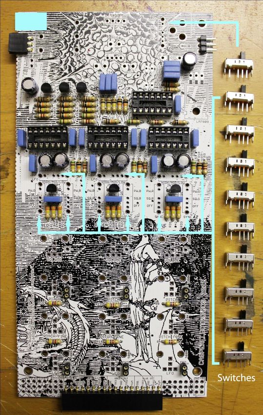
Part I: Parts Kit
Part II: Tools and Technique
Part III: PCB Assembly

                     2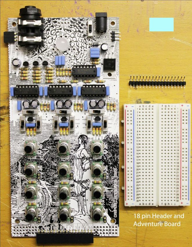
PART I: PARTS KIT

Your parts kit comes with everything you need to assemble and experiment with the NovaDrone.

In your parts kit you will find:
-1 PCB (printed circuit board)
-1 plexi glass back plate (the one shown in the following tutorial is hard fiber board).
-1 bag of electrical components. The contents of the component bag are detailed below.

Check all of your parts BEFORE you begin assembly to make sure you have everything.

                                    adventure board and back plate

                                                  3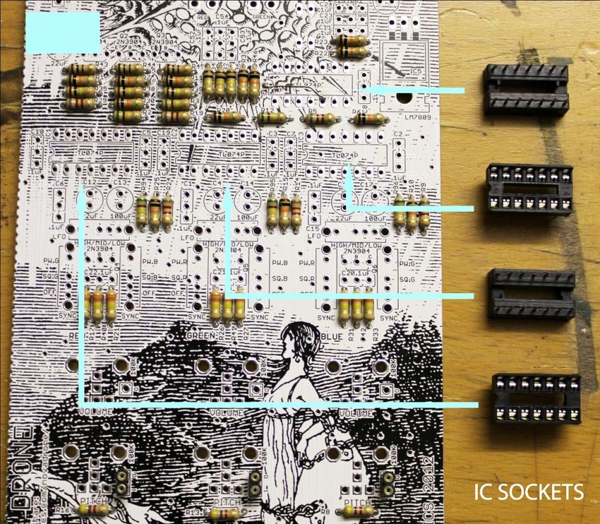
Here are all the contents of the components bag……

                            A
                                                          G

                                      F

                     Y       P                        S       I H
                                                                        K
          W                                               E
      V                             N         R
                 X           O                                          L
    D                                     Q                   I
                                                                        M
                     J                            B       C
                                                                    U

                                T

     Back Plate

                                          4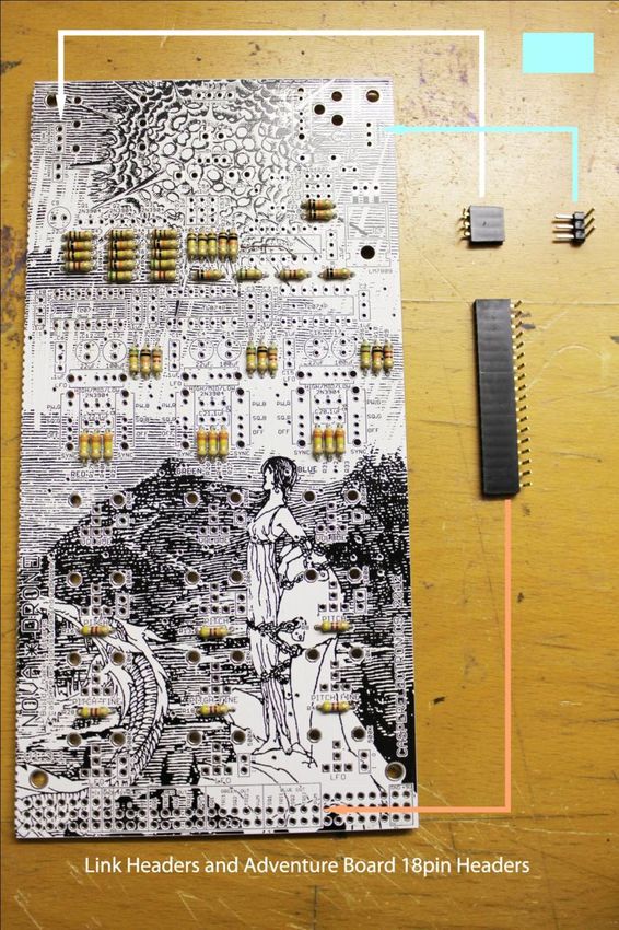
Below is a list of all the components you will be installing in the order you will install
them.
A) Resistors
(3) 100 ohm
(6) 4.7k
(6) 8.2k
(13) 10k
(6) 100k
(9) 330k
(6) 510k
B) Male and Female Link Headers
C) Female Adventure Header
D) (6) Straight Headers
E) (4) IC Sockets
F) (19) .1uF Capacitors
G) (6) 2N3904 Transistors
H) (5) 22uF Capacitors
I) (3) 100uF Capacitor
J) (10) Switches
K) (6) 100k pots
L) (3) 10k pots
M) (3) 500k pots
N) (1) 10mm common anode LED
O) 2.5mm pin power jack
P) ¼” switching audio jack
Q) 1N4001rectifier diode
R) LM7809 9 volt DC voltage regulator
S) (4) TL074 quad op-amp ICs
T) Adventure board
U) Male adventure board header
V) (2) ¾” machine screw
W) (2) 3/8” nylon spacer
X) (2) ¼” flat head machine screw
Y) (4) Nylon “acorn” machine nut / housing feet
Z) Adventure kit
(2) Light sensors
(4) LEDs
(2) 100uf Capacitors
(2) wire jumpers
5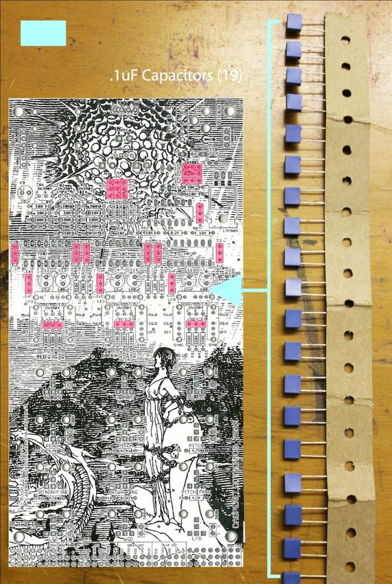
PART II: Tools and Technique
 Here are all the tools you will need for assembly

Wire nippers: These are used to clip the ends off of the component leads after
you solder them in place.

Solder: You can use any kind of solder you like but its best to use a fine “no
clean” solder. If you use generic solder like the kind sold at radio shack you can
be pretty sure it is a no clean variety. We use .032” 60/40 rosin core solder.

Soldering Iron: This is one of the most important tools in your workshop. I use a
Weller brand WES51soldering station. The WLC100 is a nice alternative at
about half the price.

If you’re new to the soldering game, here’s a link to a bunch of helpful soldering
tutorials:

http://www.ladyada.net/learn/soldering/thm.html

Small Flat head screwdriver: this will be vary useful for prying up and pressing
down components at various stages of assembly, such as the ICs and header
leads. Its also useful for tightening the back plate hardware

Needle-nose pliers: These will be useful for bending and are generally good to
have around.

                                          6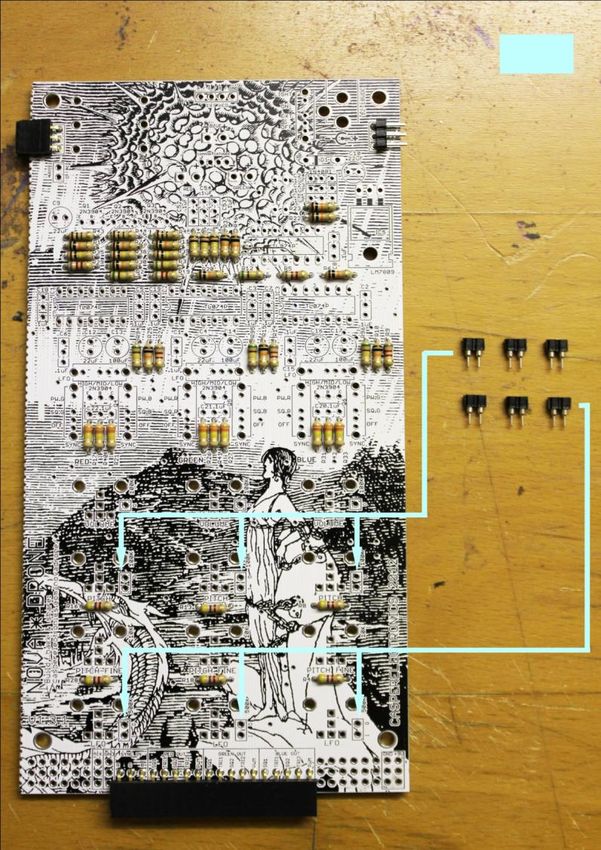
THE MIRACLE OF CLAMPING
                                                      Clamping is a method of assembly which
                                                      will save you a ton of time and is easy to do
                                                      BUT it requires you assemble the
                                                      NovaDrone in a particular order so PLEASE
                                                      read the instructions below!
                                                      Basically you will place all components of
                                                      the same height into the PCB and clamp
                                                      them in place using the back plate and the
                                                      provided rubber bands. Then you can flip
                                                      the board and all components are held
                                                      tightly in place. This will save you a lot of
                                                      time. It also helps hold tricky components
                                                      (like the slide switches) in place.

1.   Populate the PCB with components of the same height (order shown above)
2.   Place the back plate on top of the components
3.   Use the Rubber Bands to clamp the Back Plate to the PCB
4.   Flip the Clamped PCB over
5.   Check the profile of your components to make sure they are clamped tight to the board.
6.   Solder all the leads
7.   Remove back plate
8.   Clip off the soldered leads
9.   Move to the next tallest components and repeat

                                             7
PART III: PCB ASSEMBLY
We will be assembling the PCB in the following order
   1. Resistors
   2. Connection headers
   3. Modulation headers
   4. IC sockets
   5. .1uF caps
   6. Transistors
   7. 22&100uF Caps
   8. Switches
   9. Pots
   10. Remaining hardware (LED, regulator, rectifier, audio and power jacks)
   11. Adventure board
   12. Back plate

                                 1:      RESISTORS

                                              8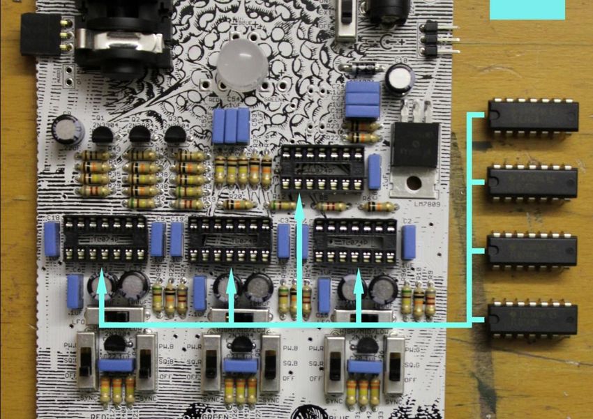
100Ω (3)        4.7k (6)

8.2k (6)        10k (13)

100k (6)        330k (9)
  (6)

510k (6)

            9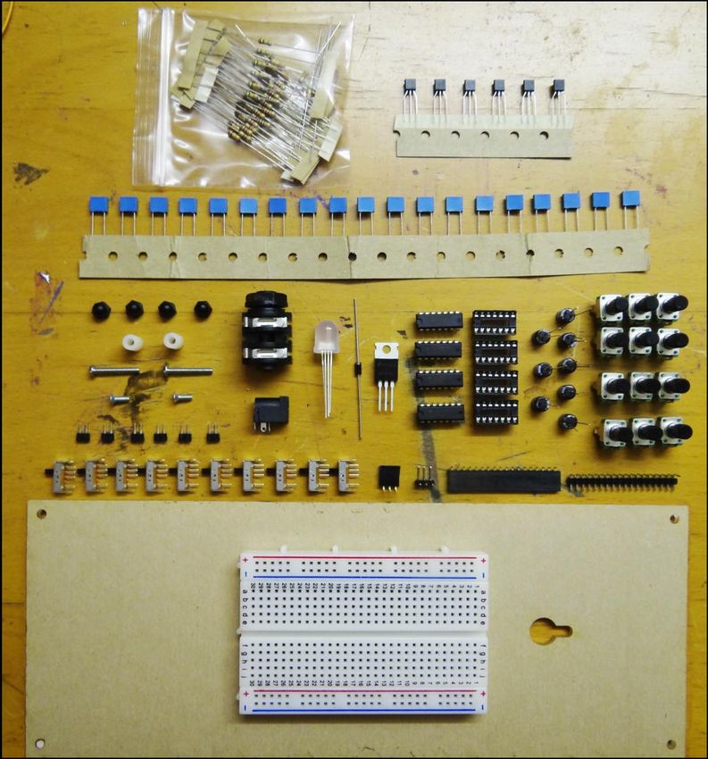
2:   CONNECTION HEADERS

                 Make sure to install the male 3 pin and
                 large female header as shown below. They
                 are VERY difficult to fix if done incorrectly.
                 The 3 pin header should be installed so the
                 metal legs come out of the plastic foot
                 parallel to the PCB. The large header
                 should be installed in the second row in.

           10
3: MODULATION HEADERS
These headers allow you to patch into
the rate controls for the oscillators and
LFOs. For instance plugging the
provided light sensors into these
sockets will allow you to control the
rates with light.
114: IC SOCKETS
125: .1uF CAPACITORS
136: TRANSISTORS
NOTE: Transistors are polarized. Make sure they are installed correctly with the flat side
pointing down.
147: 22uF and 100uF CAPACITORS
NOTE: These capacitors are polarized and must be placed in correctly. The
positive leg of the capacitor is marked on the board with a small “+”. The negative
leg of the capacitor is marked on the cap housing with a line of “-“ marks. Also
notice that the 20 and 100uF caps look very similar. The value of each cap is
written on the side.
158: SWITCHES
NOTE: The switches can be a little tricky to install correctly. Please
read the installation instructions below.
16The switches fit a little loosely into the
board and have a tendency to move before
you are finished soldering them in place.
Once the switches are fully installed it is
nearly impossible to reposition or remove
the switch without destroying it, so take
your time on this step.
The first step is to clamp your switches in
place and then look carefully from the side
to see if any of them are in crooked.
Then solder JUST ONE solder point on
EACH switch. Remove the clamp and back
plate and flip the board over. Double check
to see if the switches are in straight. If
there is a problem simply melt the solder
on the single point and reposition the
switch.
If everything looks good, finish soldering all
6 of the solder points on the switches
179: POTENTIOMETERS
(3) 100k pots (3) 10k pots
(3) 500k pots
Just like the switches, the Solder one leg and remove Once they look good, finish
pots take a little care and the back plate. Look at the soldering the 5 legs. Make sure the
patience to install correctly. pots to see that they all line two large legs are completely
Clamp the pots in place up evenly. soldered in place. Apply JUST
and look closely to see if enough solder to fill the hole that
. the legs poke through.
they are in straight.
1810: REMAINING HARDWARE
19The final components are installed one at a time and will not be clamped in
place. Each requires some special attention which is outlined below.
LM7809 voltage regulator
Bend the LM7809 regulator leads at a right angle with pliers, and place in the board.
1N4001 rectifier
NOTE: the rectifier is polarized and must be installed as shown below.
20Tri-color LED
NOTE: The LED is polarized
and must be installed correctly.
As seen in the image to the left,
the four leads of the LED have
different lengths. You must place
the LONGEST lead in the
SQUARE hole.
¼” audio jack & DC power jack
Make sure the power and audio jacks are tight against the board and
well soldered. These points will receive lots of mechanical strain and
will cause dramatic malfunctions if they come loose.
21IC sockets
NOTE: ICs are polarized. There is a little
half circle notch on one side of the IC. This
should match the notch on the IC socket
which in turn matches the notch drawn on
the PCB. Installing the ICs can be a little
tricky. The IC leads are flared out a bit wider
than the socket will accept. Bend them in
slightly with your fingers, and then try to
press all the leads into the sockets in one
shot. Check carefully to see if any of the
leads have bent under between the socket
and IC. If they have, don’t panic, just remove
with a screwdriver, carefully straighten the
22
leads and try again. You can do it!11: ADVENTURE BOARD
You’re almost done! Now we will prepare the Adventure Board for
installation.
23Press the Male 18 pin
adventure header into the
board. The right most pin of
the header should plug into
hole # 7 on the adventure
board.
The legs of the header are
just a little bit too short to sit
tightly in the adventure
board. In order to get a solid
connection it is necessary to
push the pins down one at a
time as far as they will
extend. Use a small flat
headed screw driver or
similar tool to do this.
2412: Back plate
NOTE: Your kit contains a plexi glass back plate unlike the wooden one below.
25The two ¾” screws Turn the PCB over Then slip the back And screw on the feet
go in the back two and slip the stand- plate onto the
holes of the PCB offs onto the screws. screw ends.
The final back foot assembly should look like this.
26Install the ¼” screws and attach the 2 remaining feet.
27Connecting the adventure board
Plug the male header on the adventure
First, peel off the backing. board into the female header on the PCB.
Push the edge of the board right up to the
Make sure to hold the board away from the
solder points on the PCB.
back plate.
Position the board and PCB so they are Press the adventure board firmly against
centered. the back plate.
28SHAZZAM! 29
30
You can also read