Alert-2 Microprocessor Based Digital Alarm System v5.9 - Operating & Maintenance Manual
←
→
Page content transcription
If your browser does not render page correctly, please read the page content below

Operating & Maintenance Manual
Alert-2 Microprocessor Based
Digital Alarm System v5.9

              w w w . a m i c o . c o m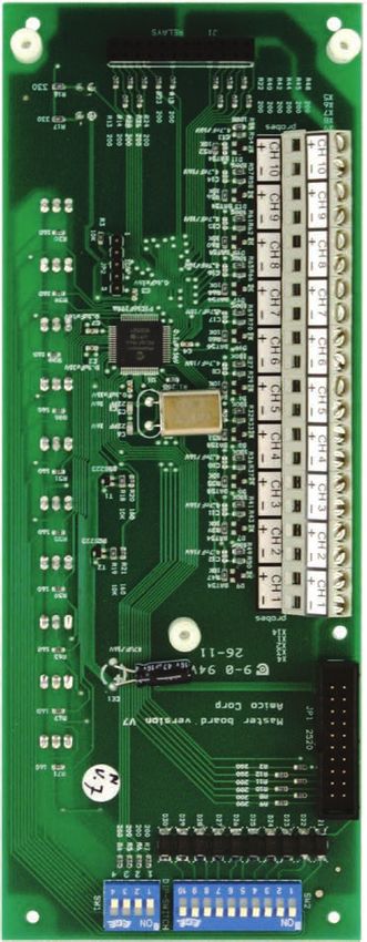
Contents
       User Responsibility                             5

       Introduction                                 5-6
              Features

       Description of the Alarm
              Shipment Details
              The Alarm Back Box
              The Frame/Module Assembly
              Description of the Modules            7-10
              Common to all Alarms
                     System Power Supply
                     Annunciator Module
                     Blank Module
              Area Alarm
                     Area Display Module
                     2 in 1 Display Module
                     Compact Display Module
                     Sensor Module
              Master Alarm
                     Master/Nema 4 Status Module
                     Computer Interface Module

       Installation Guide                          10 - 11
               The Alarm Back Box
                      For Local Sensor Only
                      Standing Pressure Test
               Frame/Module Assembly
               Sensor
                      Local
                      Remote

       Wiring                                      12 - 14
                System Power Supply
                Annuciator Module
                Sensor Module
                        Local
                        Remote
                Area Display Module
                2 in 1 Display Module
2   Amico Pipeline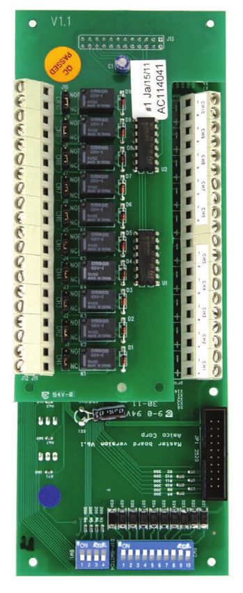
Area Display Module
       2 in 1 Display Module
       Compact Display Module
       Master/NEMA 4 Status Module
       Computer Interface Module
       Closing the Frame Module Assembly

Annunciator Module                                           14
     Noise Level Control
     Control of Remote Alarm Buzzer

Steps to Re-Calibrate the Sensor from Area Module v4.0       15

Area, 2 in 1, Compact Display Module                     15 - 19
       PSI/kPa/ BAR selection
       Inch Hg/kPa/BAR selections
       Common Settings for Pressure and Vacuum
       Setting Factory Default
       Setting Gas Identification Switches
       Chart of Gas Specific Settings of Dip-Switches

Master/NEMA 4 Status Module                              19 - 21
      Repeat Alarm
      Signal Input Selection
      Maintenance Mode

Troubleshooting Guide                                    22 - 24

Error Code Messages on the Display Module                    24

Model Numbers                                            25 - 28
      Area Alarm
      Master Alarm
      Compact Alarm
      NEMA 4 Alarm
      Compact Master Combination Alarm
      2 in 1 Area Alarm

Spare Part Numbers                                       29 - 31

                                                         www.amico.com   3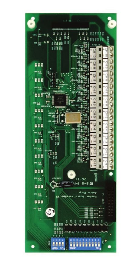
Dimensions                                                                  32 - 37
            Area Alarm
            Master Alarm
            Compact Alarm
            Compact Master Alarm Combination
            2 in 1 Alarm
            NEMA 4

       Appendix A - Wiring Diagram: Auto-Switching Power Supply                        38

       Appendix B - Wiring Diagram: Annunciator                                        39

       Appendix C - Wiring Diagram: Automatic Voice/Pager Dialing System               40

       Appendix D - Wiring Diagram: Area Display Module (Local Sensor)                 41

       Appendix E - Wiring Diagram: Area Display Module (Remote Sensor)                42

       Appendix F - Wiring Diagram: 2 in 1 Display Module                              43

       Appendix G - Wiring Diagram: Compact Module                                     44

       Appendix H - Wiring Diagram: Area Module to Master Module                       45

       Appendix I - Wiring Diagram: 2 in 1 Module to Master Module                     46

       Appendix J - Wiring Diagram: Abnormal Condition                                 47

       Appendix K - Wiring Diagram: Area Slave                                         48

       Appendix L - Wiring Diagram: Master/NEMA 4 Module                               49

       Appendix M - Wiring Diagram: Pressure Switch Connection to a Master Alarm       50

       Appendix N - Wiring Diagram: Computer Interface Module                          51

       Appendix O - Wiring Diagram: Master to Slave Module                             52

       Appendix P - Technical Specification                                            53

       Notes                                                                       54 - 55

4   Amico Pipeline
User Responsibility
   Amico Microprocessor Based Alarm

   USER RESPONSIBILITY
The information contained in this Installation and Operation Maintenance Manual, pertains only to the ALERT-2 micro-
processor  basedcontained
  The information   digital alarm.     This product
                              in this Installation      will perform
                                                   and Operation       to conformity with the descriptions contained in this manual,
                                                                 Maintenance
when  assembled,
  Manual,            operated,
           pertains only           maintained
                         to the ALERT-2             and serviced
                                            microprocessor   based in accordance
                                                                   digital alarm. with the installation instructions provided.
   This product will perform to conformity with the descriptions contained in this
   manual, when assembled, operated, maintained and serviced in accordance
Thewith
     alarm    must beinstructions
        the installation checked provided.
                                    periodically. Parts that are broken, missing,     worn, distorted or contaminated, must be
replaced   immediately.
   The alarm               Should
               must be checked      such repair
                                periodically. Partsorthat
                                                       replacement     become necessary, please contact Amico Corporation or their
                                                          are broken, missing,
distributors.
   worn, distorted or contaminated, must be replaced immediately. Should such
   repair or replacement become necessary, please contact Amico Corporation
   or their distributors.
All All
    alarms   should
        alarms shouldnot
                      not be repaired,ororaltered
                          be repaired,        altered  without
                                                    without prior prior
                                                                   writtenwritten or verbal approval of Amico Corporation or its distributors.
                                                                           or verbal
Failure   to comply
    approval  of Amicowill void allorwarranty
                       Corporation                 on the
                                       it’s distributors.   alarm.
                                                          Failure to comply will void
   all warranty on the alarm.
   Statements in this manual preceded by the words WARNING, CAUTION,
Statements    in this manual preceded by the words WARNING, CAUTION, DANGER and NOTE are of special significance.
   DANGER and NOTE are of special significance. Please read these sections
Please  read these sections carefully.
   carefully.

NOTE: Amico strongly recommends that alarms be checked annually by qualified staff.

                  WARNING: denotes WARNING:    denotes
                                   steps which can       steps
                                                   prevent injury.which can prevent injury.

                                   CAUTION:
                  CAUTION: denotes steps       denotes steps which can prevent damage to
                                         which can prevent damage to equipment.
                                      equipment.

                                         DANGER: denotes steps which can prevent electrical
                  DANGER: denotes steps which can prevent electrical shock to equipment
                                         shockand/or
                  or to prevent serious injury to equipment
                                                     death. or to prevent serious injury and/or
                                         death.

    Introduction
The AMICO Medical Gas Alarm System (ALERT-2) incorporates the latest microprocessor technology for alarm and
surveillance systems. The alarm has been designed to provide user flexibility and reliability. This manual will enable the
customer to install, use and maintain the alarm properly.

All PGases
      a g e : or
               4 Vacuum are displayed with large Red LED’s for clear visibility. To facilitate the monitoring function by hospital

personnel, a trend bar is provided to show the direction of the gas/vacuum pressure. Under normal operation, the gas
trend indicator will be in the GREEN - OK position. If the gas pressure approaches alarm condition, the trend indicator
will display a YELLOW - Caution indicator. If an alarm condition occurs, a RED-Alarm indicator will be displayed and the
buzzer will sound.

There are two buttons located on the front face of the Annunciator module. They are the “TEST” and “ALARM MUTE”
buttons. The function of the “Test” button is to verify that the buzzer and all the alarm LED’s are in normal working condition.
The function of the “Alarm Mute” button is to silence an alarm that has occurred.

A master status module monitors source equipment such as: Oxygen, Nitrous Oxide, Air compressors, Vacuum pumps,
Air dryers, high/low pressure switches, etc. This module can be connected to a “Building Management System”, with a
piggy-back computer interface board, that attaches to the master module.
                                                                                                                           www.amico.com         5
The Alert-2 microprocessor based digital alarm system complies with NFPA-99.

    The Alert-2 microprocessor based digital alarm system is UL Listed to U.S. and Canadian safety standards.

    FEATURES

           Individual Microprocessor on each display, sensor and master module.

           Gas specific sensors can be mounted locally or remote, up to 2,500 feet, [750m] utilizing 22 gauge twisted pair
           (shielded cable should be used).

           DISS gas specific sensor housed in a tamper proof enclosure. The Sensor Module is housed in an anodized aluminum
           and nickle-plated brass enclosure to act as an interference barrier.

           The Sensor Module is the smallest computer-calibrated temperature-compensated sensor in the industry.

           True digital LED display and trend indicator for each service monitored.

           Illuminated LED display that is visible at an angle and in dim lighting conditions.

           PSI, kPa or BAR display (switch selected).

           Self diagnostic circuitry with error display for problem identification.

           Highly accurate Solid State Pressure piezo-resistive transducer.

           Adjustable repeat alarm (1 to 60 minutes/or off ) for the Area, 2 in 1 Alarm and Compact Alarm.

           Adjustable repeat alarm (1, 12, 24 hours/or off ) for the Master Alarm.

           Dry contacts for remote monitoring of High and Low alarm status on the Area, 2 in 1 and Compact Alarm display
           module.

           Modules are factory mounted on a hinged frame assembly for ease of installation and maintenance.

           Field programmable push buttons for adjustment of HI and LOW set-points on display module.

           Area alarms available in 1 to 6 display modules.

           Compact alarms available in 1 to 12 display modules.

           Master alarms available in 10 to 60 points.

           2 in 1 alarms available in 1 to 6 display modules with 5 to 30 master points.

           Area, 2 in 1, and Compact Modules can be intermixed with Master Modules to create a combination alarm.

           Built-In relay for remote annunciator applications.

           Area, 2 in 1 and Compact Module indication for calibration (flashing bar graph).

6     Amico Pipeline
Description of the Alarm
SHIPMENT DETAILS

When you receive an ALERT-2 series alarm from Amico Corporation, the package will consist of two main sections; the
Alarm Back Box and the Frame/Module Assembly. The Frame/Module assembly will be pre-configured, with the appro-
priate display modules, based upon the customer’s specifications.

THE ALARM BACK BOX

The Alarm Back Box contains the auto-switchable System Power Supply with an ON/OFF switch, a built-in fuse and ter-
minal blocks (115 VAC, or 220 VAC). The back box also incorporates the pipe stubs for applications that require locally
(in box) mounted sensors.

THE FRAME/MODULE ASSEMBLY

The Frame/Module Assembly consists of the frame and all the modules that are pre-assembled to the customers speci-
fication. The hinged frame is designed to swing down from the back box to facilitate installation and servicing of the
alarm. This design will reduce installation time and eliminate the risk of improper installation since all the modules are
connected and tested at the factory.

   Description of the Modules
The ALERT-2 alarm is divided into 4 or 7 main modules:

COMMON TO ALL ALARMS

1. SYSTEM POWER SUPPLY

The System Power Supply has been pre-installed into the back box assembly. The System Power Supply converts the
AC voltage supply to the alarm into two voltages: 5 VDC (regulated) required by the microprocessor hardware and 15
VDC (unregulated) required by the buzzer and the LED’s. This unit also contains the main ON/OFF power switch, the
transformer, the heat sink, the main fuse and fuse cover, the rectifying circuitry, the terminal blocks and the low voltage
DC power cable for connecting this unit to the annunciator module. The System Power Supply can be easily removed
and reinstalled by unscrewing it from the back box.

                                                                                                          www.amico.com       7
sw
re
ca
Po
fro
2. ANNUNCIATOR MODULE
2.
The Annunciator Module contains the buzzer, a “Power On” LED, the “TEST” and the Th
“ALARM MUTE” buttons. The function of the “TEST” button is to verify that the buzzer and all “T
the LED’s are in working condition. An alarm will be heard when this button is pushed and bu
all the LED’s will light up. When the button is released, the alarm will silence. The “ALARM MUTE” tio
button is used to silence an alarm that has occurred. This module also contains a fail-safe relay wi
that de-energizes when the buzzer is activated. This relay can be used with the “Amico remote “A
buzzer”, for applications requiring a remote audible alarm (see Appendix B), for connection to m
is
another Amico Alarm or a Building Management System.
ap
co
3.
3. BLANK MODULE Alert - 2 Series
Alert - 2 Series Th
al
The Blank Module is used as a filler board for future provisions of the alarm.
AREA ALARM
AREA ALARM
4. AREA DISPLAY MODULE
4. AREA DISPLAY MODULE
AREA ALARM The Area Display Module provides a digital display of the actual
The Area Display Module provides a digital display of the actual
pressure/vacuum of a gas being monitored. In addition a gas trend
4. AREA DISPLAY MODULE pressure/vacuum of a gas being monitored. In addition a gas trend
indicator bar with HIGH and LOW alarms are displayed. The trend
indicator bar with HIGH and LOW alarms are displayed. The trend
bar has three coloured LED’s: GREEN for Normal condition, YEL-
bar has three coloured LED’s: GREEN for Normal condition, YEL-
The Area Display ModuleLOWprovides
LOW for
for Caution
Cautiona digital display
condition,
condition, and
andof the
RED
RED actual
for pressure/vacuum
for high
high and
and low Alarmof a
low Alarm
gas being monitored. In addition
conditions.
conditions. a gas trend indicator bar with HIGH and LOW alarms
are displayed. The trend bar has three coloured LED’s: Green for Normal condition, YELLOW
for Caution condition, and RED for high and low Alarm conditions.
Each
Each display
display module
module contains
contains a a gas
gas specific
specific colour
colour coded
coded label
label
(USA or ISO colours are available). A space is also provided, at Page: 8
Each display modulebase(USA
containsor ISO colours
a gas specific are available).
colour coded A space
label (USA is also
or ISO provided,
colours at the
are the
of the module, to identify the location that
base of the module, to identify the location that the display module the display module
available). A space is also provided,
monitors.
monitors. Theatdisplay
The the base
display of the module,
module
module is
is field to identify the
field adjustable
adjustable for location
for that
pressure/vacuum
pressure/vacuum
the display module monitors.
settings, The display module is field adjustable for
settings, repeat alarm, and units of measure. Whenever the module
repeat alarm, and units of measure. pressure/vacuum
Whenever the module
settings, repeat alarm,is
isand
in units of measure.
in calibration
calibration mode,Whenever
mode, the
the bargraph
bargraphthe module
is is in calibration
is flashing,
flashing, indicating mode,
indicating the
the calibra-
calibra-
the bargraph is flashing,
tion indicating
tion mode. Drythe
mode. Dry calibration
contacts
contacts for mode.
high
for high and
and Drylow
low contacts
alarmsfor
alarms arehigh
are and low
available
available for
for
remote monitoring of each
alarms are available for remote monitoring of each module.
remote monitoring of each module.
module.
5. 2 IN 1 DISPLAY MODULE
5. 2 IN 1 DISPLAY MODULE
5. 2 IN 1 DISPLAY MODULE
The 2 in 1 Display Module provides a digital display of the actual
The 2 in 1 Display Module provides a digital
pressure/vacuum display
of the of the actual
gas being pressure/vacuum
monitored. In addition,of a the
gas
trend indicator bar with High and Low alarms are displayed.
gas being monitored. In addition, a gas trend indicator bar with High and Low alarms are This
module has two coloured LEDs - green for Normal conditions
displayed. This module has two coloured LEDs - Green for Normal conditions and Red for and
red for High and Low alarm conditions. It is field adjustable for
High and Low alarm conditions. It is field adjustable for pressure/vacuum settings, repeat
pressure/vacuum settings, repeat alarms, and units of measure.
alarms, and units of measure.
Dry contactscontacts
Dry for highforand
highlow
andalarms
low alarms are available
are available for for remote
remote
monitoring of each module.
monitoring of each module.
Each module will continuously monitor
Each module willup to 5 signals from
continuously source
monitor up equipment
to 5 signalsorfrom
pressure
source
switches. If any of theequipment
signals being monitoredswitches.
or pressure go into anIfalarm condition,
any of a Red
the signals LED will
being
illuminate and the audible alarmgo
monitored willinto
sound.
an alarm condition, a red LED will illuminate and
the audible
the audible alarm
alarm will
will sound.
sound.
PLEASE NOTE: Contacts located
Please
Please Note:onContacts
Note: back of module
Contacts locatedare
located onDry
on Contacts
back
back of only. are
of module
module are Dry
Dry Contacts
Contacts
DO NOT apply any voltage.
only. DO NOT apply any voltage.
only. DO NOT apply any voltage.
8 Amico Pipeline 6. SENSOR
6. SENSOR MODULE
MODULE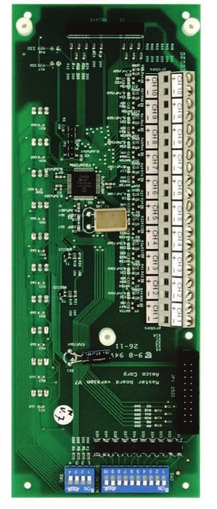
6. COMPACT DISPLAY MODULE

The Compact Display Module shall have 2 displays in 1 board. The Compact Module
provides a digital display of the actual pressure/vacuum of a gas being monitored. In
addition a gas trend indicator bar with High and LOW alarms are displayed. The trend bar
as two colored LED’s: GREEN for Normal and RED for High and Low condition.

Each display module contains a gas specific colour coded label (USA or ISO colours are
available). The Display Module is field adjustable for pressure/vacuum settings, repeat
alarm, and unit of measure. Dry contacts for high and low alarms are available for remote
monitoring of each module.

7. SENSOR MODULE

The Sensor Module contains the transducer which converts the pressure/vacuum pres-
sure source into a digital signal that is displayed on the Display Module. The sensor
module shall be housed in an anodized aluminum and nickel-plated brass enclosure
to act as an interference barrier also it is temperature compensated. Each sensor is
clearly labeled and colour coded for the gas or vacuum being monitored. The sen-
sor module contains a gas specific DISS fitting to ensure correct connection of the proper
sensor to the respective gas. Each sensor has been factory calibrated by computer for the
specific gas shown on the sensor housing. If it is not connected to the appropriate gas
display module, an error message (EO2) will be displayed.

MASTER ALARM

8. MASTER/NEMA 4 STATUS MODULE

Each Master Status Module will continuously monitor up to 10 signals from source equipment
and pressure switches. If any of the signals being monitored go into an alarm condition, a
Red LED will illuminate and the audible alarm will sound. The module has a slow and
a rapid flashing LED rate. The last alarm condition always flashes at a rapid rate, while the
previously acknowledged alarms always flash at a slow rate.

PLEASE NOTE: Contacts located on back of module are Dry Contacts only.
DO NOT apply any voltage.

For Annual Test
• Reset power to make sure all LED’s light up
• Push and hold the ‘Test’ button to light up all LED’s and the audible alarm

                                                                                                www.amico.com   9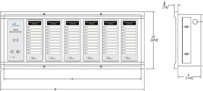
8.   COMPUTER INTERFACE MODULE
                                                                                                            The Computer Interface Module is a piggyback board
                                                                                                            master status module. This module plugs into the st
                                                                                                            connector, located at the bottom end of the status mo
                                                                                                            mounting screws provided to secure this module to t
                                                                                                                                                  This module p
 9. COMPUTER INTERFACE MODULE                                                                                                                     for interface to
                                                                                                                                                  ment System”
                                                                                                                                                  Safe”, closed
                                                                                                                                                   NOTE: The c
 The Computer Interface Module is a piggyback board that fits on top of the master                                                                 module is not
                                                                                                                                                   in 1 board.
 status module. This module plugs into the status module via a connector, located at the
 bottom end of the status module. There are three mounting screws provided to secure this
 module to the status module. This module provides dry contacts for interface to a “Build-
 ing Management System”. The module is “Fail-Safe”, closed circuit monitoring.

 PLEASE NOTE: The computer interface module is not compatible with the 2 in 1 board.
                                                                                             Page: 10

     Installation
 THE ALARM BOX

 Install the back-box to the studs of the wall at the desired height. Ensure that the box is securely in place. The mounting
 brackets are adjustable to suit the thickness of the wall. MAKE SURE the box is parallel, squared and flush with the finished wall
 surface, to ensure that the frame assembly will fit properly.

 FOR LOCAL SENSOR ONLY

 If the sensors are to be mounted locally (inside the back box), the pipe stubs must be connected to the pipeline. Using
 silver-brazing techniques, connect each pipe stub to it’s appropriate gas or vacuum while ensuring that the bottom of
 the pipe stub is wrapped with a damp cloth. BE CAREFUL not to damage the DISS check-valve by overheating the lower
 portion of the copper pipe. When the brazing of pipe stubs has been completed, the system can be pressure tested.

 STANDING PRESSURE TEST

 Perform a standing pressure test on the piping system as per NFPA-99 “Health Care Facilities”. Inspect all joints for leaks
 and make certain each gas is piped to a correspondingly labelled gas service.

 FRAME/MODULE ASSEMBLY

 Step #1          Remove the frame/module assembly from its protective box.

 Step #2          Remove screws from the frame section (6 screws).

 Step #3          Attach the flat head screws (provided with frame in plastic bag) to the hinge. This will line up with holes
                  on the box.

 Step #4          Attach the frame wire with 2 dome head screws (provided with frame in plastic bag).

 Step #5          Close the frame panel and tighten the screws on the frame plate.

 Step #6          Carefully place the front frame over the fastened plate. Refasten the screws that were removed in Step #2.

10   Amico Pipeline
Amico Microprocessor Based Alarm
CAUTION: The microprocessor circuitry on the ALERT-2 alarm con-
tains sophisticated integrated semiconductors. If it becomes necessary
CAUTION: The microprocessor circuitry on the ALERT-2
to remove alarm
a module, PLEASEcontains sophisticated
hold the boards integrated
by the edges. DO NOT semiconductors. If it
becomes necessary to remove a module, PLEASE cause hold the boards by the
to malfunction, edges. DO NOT TOUCH any of the components
TOUCH any of the components on the board. Static discharge can
the modules or become damaged.
on the board. Static discharge can cause the modules to malfunction, or become damaged.
SENSOR
LOCAL (In the Back Box)
SENSOR
1. Locate the gas specific
LOCAL (Inside the Back Box) A m i c o M i c r o pstalled.
sensor module to be in-
rocessor Based Alarm
2. In the back box, there are
1. Locate the gas specific sensor module to be installed. colour coded gas labels
located under CAUTION:
the DISS The microprocessor circuitry on the ALERT-2 alarm con-
A m i c o M i c r o p r o c e s s o rDemand
B a s e dcheck
A l a valves. Each
label identifiestains sophisticated integrated semiconductors. If it becomes necessary
rm
where each
2. In the back box, there are colour coded gasCAUTION: labels located
sensor module tois remove
to be a module, PLEASE hold the boards by the edges. DO NOT
placed. The microprocessor circuitry on the ALERT-2 alarm con-
under the DISS Demand check valves. Each label
tains
3. to The
identifies
sophisticated
sensor
remove
TOUCH
module
a module,
integrated
contains
PLEASE
any
hold
of the components
semiconductors. on the board. Static discharge can
If it becomes necessary
the boards to
by the edges. DO NOTor become damaged.
cause the modules malfunction,
where each sensor module is to be placed. TOUCH a gas specific
any of theDISS fitting. on the board. Static discharge can
components
Pushthe
cause themodules
sensor to module
malfunction, or become damaged.
hex-nut and nipple adapter
3.
up into the demand check-
The sensor module contains a gas specific DISS
SENSOR fitting.
valve. SENSOR Push tighten the nut so that it makes a good seal.
With a wrench,
the sensor module hex-nut and nipple adapter up into
NOTE: Pressure the are not to exceedOLD
on sensors
LOOK
250psi
demand check-valve. With a wrench, tighten thefor nut
LOCAL (In the
so sensors
Back
Pressure that and 30” for Vacuum sensors
Box)
LOCAL (In the Back Box)
it makes a good seal. 1. Locate the gas specific
sensorthe
REMOTE (Outside module
BacktoBox)
be in-
stalled.
NOTE: Pressure on sensors are not to exceed 250psi
1. for
Connect
thePressure
2. by others)
In
a Tee1.
back
Locate the gas specific
(supplied
box,
to the there are
pipeline
sensors and 30” for vacuum sensors. withcolour
a 1/4"coded sensor module to be in-
gas labels
NPT female
located under the DISS stalled.
connection that will accept
Demand check valves. Each
the DISS Demand check-
label identifies where each
valve.
sensor module2. is toIn
be the back box, there are
2. Locate the gas specificcolour coded gas labels
placed.
3. sensor
The module to be contains
sensor module located under the DISS
The new style sensors can read pressure up to: installed.
a gas specific DISS fitting.
PushthetheDISS
sensor Demand check valves. Each
module
3. Thread Demand
Mid Pressure 99 Psi hex-nut and
check-valve intonipple label identifies where each
the adapter
up into
gasthe demand check-
Hi Pressure 249 Psi correct pipe line. sensor
valve. With a wrench, tighten themodule
nut so thatis to bea good seal.
it makes
Vacuum 30” Hg
4. The sensor module contains placed. a gas specific DISS fitting. Push the
NOTE: Pressure on sensors are not to exceed 250psi
sensor module hex-nut and nipple adapter up into the demand NEW LOOK
for Pressure
check-valve. 3. sensors
With a wrench,
The 30” for
andtighten
sensor theVacuum sensors
nut so that
module itcontains
makes a
good seal.
a gas specific DISS fitting.
Page: 12
REMOTE (Outside the Back Box) Push the sensor module
1. hex-nut and nipple adapter
Connect a Tee (supplied
REMOTE (Outside the Back Box) up into the demand check-
by others) to the pipeline
with a 1/4" NPT female
valve. With a wrench, tighten the nut so that it makes a good seal.
connection that will accept
1. Connect a Tee (supplied by others) to the pipeline
valve. with a Pressure on sensors are not to exceed 250psi
the DISS Demand check-
NOTE:
1/4” NPT female connection that will accept the DISS Demand for Pressure sensors and 30” for Vacuum sensors
2. Locate the gas specific
sensor module to be
check-valve. installed.
3. Thread the DISS Demand
check-valve into the
2. Locate the gas specific sensor module to be installed.
OLD LOOK
correct gas pipe line.
REMOTE (Outside the Back Box)
4. The sensor module contains a gas specific DISS fitting. Push the
sensor module hex-nut and nipple adapter up into the demand
1.With a Connect a Tee
the nut(supplied
3. Thread the DISS Demand check-valve into the correct gas check-valve.
good seal.
wrench, tighten so that it makes a
by others) to the pipeline
pipe line. Page: 12 with a 1/4" NPT female
connection that will accept
4. The sensor module contains a gas specific DISS fitting. Push the DISS Demand check-
the sensor module hex-nut and nipple adapter up into the valve.
demand check-valve. With a wrench, tighten the nut so2.that Locate the gas specific
it makes a good seal. sensor module to be
installed.
3. Thread the DISS Demand
check-valve into the
correct gas pipe line. NEW LOOK
4. The sensor module contains a gas specific DISS fitting. Push the
sensor module hex-nut and nipple adapter up into the demand
check-valve. With a wrench, tighten the nut so that it makes a
good seal. www.amico.com 11manual, when assembled, operated, maintained and serviced in accordance
with the installation instructions provided.
The alarm must be checked periodically. Parts that are broken, missing,
worn, distorted or contaminated, must be replaced immediately. Should such
repair or replacement become necessary, please contact Amico Corporation
Wiring
or their distributors.
All alarms should not be repaired, or altered without prior written or verbal
approvalPOWER
SYSTEM of Amico Corporation or it’s distributors. Failure to comply will void
SUPPLY
all warranty on the alarm.
TURN OFF THE
Statements in POWER SWITCH
this manual BEFOREbyCHANGING
preceded the wordsANY MODULES
WARNING AND/OR DISCONNECTING
, CAUTION , ANY CABLES, OR ELSE
and NOTE
THE FUSE WILL BLOW TO PROTECT THE CIRCUITRY.
DANGER are of special significance. Please read these sections
carefully.
1. Ensure that the ON/OFF switch is in the OFF position.
2.Through the top left side of the back box, bring in the AC power wires. Knockouts are
providedsteps
WARNING: denotes for making
whichconduit connections
can prevent injury.to the box. All wiring is to be installed according
to local and national codes.
3. Connect the AC power to the terminal blocks as shown in the wiring diagram in Appendix
A and as specified in the technical specification in Appendix P.
CAUTION: denotes steps which can prevent damage to equipment.
ANNUNCIATOR MODULE
1. DANGER: denotes
The Annunciator stepshas
Module which can receptacle
a female prevent electrical shock
located at to equipment
the top right side of the board (J1).
or to prevent serious injury and/or death.
2. Connect the DC power cable from the System Power Supply into the receptacle connection located on
the annunciator module. The connector is keyed and can only be plugged in one way, (Appendix B).
SENSOR MODULE
LOCAL (Inside the Back Box)
1. The sensor module is provided with a 6”-8” [0.1m-0.2m] twisted pair of wires. One wire is Red (positive) and the
other wire is Black (negative). Connect the wires to the display module as shown in Appendix D. Take the Red
wire fromthe sensor and attach it to terminal “Sensor +” on the display module. Take the Black wire from the sensor
and attach it to terminal “Sensor -”. The terminal block on the display module is clearly marked for proper
P a connection
ge: 4 of the sensor wires.
2. Repeat the above procedures with the remaining sensor modules.
REMOTE (Outside the Back Box)
1. The sensor module is provided with a 6” - 8” [0.1m - 0.2m] twisted pair of wires. Connect the wires to a junction box
(not supplied) located near the sensor as per the wiring diagram in Appendix E.
2. Connect a shielded twisted pair cable from the junction box to the back box assembly. Knockouts are provided
throughout the alarm back box. Up to 2,500 feet [750m] of 22 Gauge, shielded twisted pair cable can be used.
12 Amico Pipeline3. Connect the Red wire from the cable to the terminal on the display module marked ”Sensor +”. Connect the
black wire to terminal “Sensor -” (see Appendix D).
4. Repeat the above procedures with the remaining sensor modules using the wiring diagram in Appendix E.
PLEASE NOTE: When remote sensors are used, a shielded or twisted pair cable is required (BELDEN #8451 or equivalent,
supplied by others). Ensure that the proper gas sensor module is connected to its corresponding area display module,
otherwise an error message (E02) will be displayed on the Area Display module.
AREA DISPLAY MODULE
1. If the dry contacts for High and Low alarm are to be used for remote monitoring, connect the wires to the appropriate
terminals, Com (Common), NO (Normally Open) or NC (Normally Closed), using the diagram in Appendix H.
2. See Appendix P for contact rating.
2 IN 1 DISPLAY MODULE
1. If the dry contacts for High and Low alarms are to be used for remote monitoring, connect the wires to the appropriate
terminals, COM (Common), NC (Normally Closed), or NO (Normally Open), using the diagram in Appendix F.
2. Pull the remote signal wires into the alarm panel. Make the connections to the terminal blocks located on the side
of the status module. The wiring fail-safe normally closed (NC) connections from the source equipment. The signal
level is 5 VDC. Please refer to Appendix I.
3. ENSURE that the unused terminals are jumpered. If this is not done, the terminals that have not been jumpered will
go into alarm.
COMPACT DISPLAY MODULE
1. If the dry contacts for high and low are to be used for remote monitoring, connect the wires to the appropriate
terminals, Com (Common), NO (Normally Open), NC (Normally Closed), using the diagram in Appendix G.
2. See Appendix P for contact rating.
MASTER/NEMA 4 STATUS MODULE
1. Pull the remote signal wires into the alarm panel. Make the connections to the terminal blocks located on the side
of the status module. The wiring is fail-safe normally closed (NC) connections from the source equipment. The
signal level is 5 VDC.
2. Make the appropriate wiring connections as per the wiring diagram in APPENDIX M and N.
3. For Version 3 ENSURE that the unused terminals in the master module are jumpered. If this is not done, the terminals
that have not been jumpered will go into alarm.
For Version 4, turn off switches for any unused points (SW2).
www.amico.com 13COMPUTER INTERFACE MODULE
Amico Microprocessor Based Alarm
1. Pull the remote signal wires from the “Building management system” into the alarm panel. Make the connections
to the terminal blocks located on the side of the module. The wiring is fail-safe normally open, held closed, dry
FIELD ADJUSTMENTS
contacts to the monitoring equipment.
2. Make the appropriate wiring connections as per wiring diagram in Appendix N.
CLOSINGTHE
THE
A m FRAME/MODULE
o M i c r o p r oASSEMBLY
i cANNUNCIATOR c e s s o r MODULE
Based Alarm
1. Swing up the frame assembly, ensuring that the stopper wires are folded into the back box.
FIELD ADJUSTMENTS
NOISE LEVEL CONTROL
2. Screw in the frame module to the top of the back box assembly by using the screws provided with the frame/module
assembly. The alarm is now ready for use!
Factory Default: 90 Decibles
THE ANNUNCIATOR MODULE LVL1
LVL2
Annunciator Module
To decrease noise level: LVL3
J5
1. Locate jumper at J5. Move jumper to:
NOISE LEVEL CONTROL
NOISE LEVEL CONTROL LVL1 = 90 dBa.
LVL2Default:
Factory = 80 dBa.
90 Decibles SILENCE
Factory Default: 90 Decibels
LVL3 = 70 dBa. LVL1
LVL2
To decrease noiseTo
level:
decrease noise level: LVL3
J5
1. Locate jumper at J5. Move jumper to:
1. Locate jumper at J5. Move jumper to:
LVL1 = 90 dBa. LVL1 = 90 dBa.
CONTROL
LVL2 = 80 dBa. OF REMOTE ALARM BUZZER
LVL2 = 80 dBa. SILENCE
LVL3 = 70 dBa.
LVL3 = 70 dBa.
Factory Default: Normal Condition
CONTROL OF REMOTE ALARM
To silence BUZZER
remote alarm buzzer when silencing the
annunciator module:
FactoryCONTROL
Default:
1. Normal
Locate Condition
OF REMOTE ALARM BUZZER
jumper at J6. Move jumper to:
To silence remote alarm buzzer, when silencing the
Factory Default: Normal Condition
annunciator module:
NORM =
J6
Remote alarm buzzer will silence when annunciator
1. Locate jumper Toatsilence
J6. Moveremote
module isjumper to:
alarm
silenced. buzzer when silencing the ALRM
NORM
annunciator module:
NORM = TEST
1. Locate jumper at J6. Move jumper to:
Remote alarm buzzer
ALRM will=silence when annunciator
module is silenced.
Remote alarm will not silence when annunciator
NORMis=silenced. The buzzer will only silence
module
ALRM = when alarm condition has
willbeen cleared.
when Please
J6
Remote alarm buzzer silence annunciator
Remote alarm willrefer
not to
silence whenB.
Appendix annunciator ALRM
module is silenced. NORM
module is silenced. The buzzer will only silence when
alarm condition has been cleared. Please refer to TEST
Appendix B. ALRM =
14 Amico Pipeline Remote alarm will not silence when annunciator
module is silenced. The buzzer will only silenceSteps to Re-Calibrate the Sensor from Area Module v4.0
1. Turn on Alarm
2. Set switches #8 & #10 the OFF position
3. Set switches #5 & #6 the ON position
4. The display will show the current reading of the pressure
5. Adjust the calibration, using the “UP” and “DOWN” push buttons, to the desired value.
6. Set switches #5 & #6 the OFF position
7. Turn on #10 if Aims is connected (do not turn on #8)
When you have completed step #7, the display module will automatically go into a “RESET” mode. This will store the
data that you had entered.
Area, 2 in 1, Compact Display Module Alert - 2 Series
THE AREA/2 IN 1 DISPLAY MODULE
A dip-switch is located on the back of the display module which is used to identify the gas of the display module. The
dip-switch
A dip contains
switch is ten switch
located onsettings.
the back of the display module
which is used to identify the gas of the display module. The
dip-switch contains ten switch settings.
PRESSURE ONLY
Factory Default: 2 in 1 Alarm
PRESSURE ONLY
High = 60 Psi, Low = 40 Psi Board
Factory Dip-Switch
RepeatDefault:
time = 30 min. Dip-Switch
Dip-Switch
High = 60 Psi, Low = 40 Psi
Repeat time = 30 min.
HIGH PRESSURE/NITROGEN
Factory Default:
HIGH PRESSURE/NITROGEN Dip-Switches
High = Default:
Factory 195 Psi, Low = 140 Psi
Repeat time = 30 min.
High = 195 Psi, Low = 140 Psi
2 in 1 Alarm Area Alarm
Area Alarm
Compact Alarm
Board Board
Board Board (v2.02)
Repeat time = 30 min.
During Programming the Compact Alarm
“Trend Bar” will Flash! Board (v2.01)
1. Set switch #6, #7 and #8 to the ON position.
2. The LED will display (HI-), followed by the current set point.
During programming, the “Trend Bar” will Flash!
Indicating the system is ready to accept a new High set point.
Adjust set point, using the “UP” and “DOWN” push buttons, to the
1. value.
desired Set switch #6, #7 and #8 to the ON position.
3. Set2. The
switch #7 toLED will display
the OFF position.(HI-), followed by the current set point. Indicating the system is ready to accept a
new High set point. Adjust set point, using the “UP” and “DOWN” push buttons, to the desired value.
4. The LED will display (LO-), followed by the current set point.
3.
Indicating Setsystem
the switchis#7ready
to the
to OFF position.
accept a new Low set point.
4. set point,
Adjust The LED will
using thedisplay (LO-),
“UP” and followed
“DOWN” bybuttons,
push the current
to theset point. Indicating the system is ready to accept a
new Low set point. Adjust set point, using the “UP” and “DOWN” push buttons, to the desired value.
desired value.
5. Set5. Settoswitch
switch #8 #8 position.
the OFF to the OFF position.
6. The6.LED will
The LED will
display (I-I-),display
followed(I-I-), followed
by the currentby
setthe current set point. Indicating the system is ready to accept a
point.
new
Indicating the Repeat
system time set
is ready point. aAdjust
to accept set point
new Repeat timeusing
set the “UP” and “DOWN” push buttons, to the desired
point. Adjustvalue. [(Display
set point using dd=Disabled)
the “UP” and “DOWN”Range from
push1buttons,
to 60 Minutes]
7. desired
to the Setvalue.
switch[(Display
#6 to the OFF position.
dd=Disabled) Range from 1 to 60
Minutes]
7. Set switch #6 to the
OFF position.
www.amico.com 15desired value.
5. Set switch #8 to the OFF position.
6. The LED will display (I-I-), followed by the current set point.
Indicating the system is ready to accept a new Repeat time set
point. Adjust set point using the “UP” and “DOWN” push buttons,
to the desired value. [(Display dd=Disabled) Range from 1 to 60
Minutes]
7. Set switch #6 to the
When you have completed step #7, the display module OFF position.
will automatically go into a “RESET” mode. This will store the
data that you had entered. When you have completed
step #7, the display module
will automatically go into a
“RESET” mode. This will store
the data that you had entered.
Page: 17
PSI / kPa / BAR selection
PSI
Factory Default - PSI
For PSI mode, set the switch #4 to the ON position. The LED PSI indicator located next to the GAS
pressure reading will illuminate.
For kPa mode, set the switch #4 to the OFF position and switch #9 to the ON position. The LED kPa
indicator located next to the GAS pressure reading will illuminate. KPA
For BAR set the switch #4 to the OFF and the switch #9 to the OFF position. The LED kPa indicator
located next to the GAS pressure reading will illuminate. (There is no separate indicator for BAR).
VACUUM ONLY
BAR
Vacuum alarm set-point adjustment
Factory Default:
High = 30”Hg, Low = 12”Hg
Repeat time = 30 min.
During programming, the “Trend Bar” will Flash!
1. Set switch #6, #7 and #8 to the ON position.
2. The LED will display (HI-), followed by the current set point. Indicating the system is ready to
accept a new High set point. Do not adjust this set point since the High set point is not used.
3. Set switch #7 to the OFF position.
4. The LED will display (LO-), followed by the current set point. Indicating the system is ready
to accept a new Low set point. Adjust set point, using the “UP” and “DOWN” push buttons, to
the desired value.
5. Set switch #8 to the OFF position.
6. The LED will display (I-I-), followed by the current set point. Indicating the system is ready to
accept a new Repeat time set point. Adjust set point using the “UP” and “DOWN”push buttons,
to the desired value. [(Display dd=Disabled) Range from 1 to 60 Minutes]
7. Set switch #6 to the OFF position.
When you have completed step #7, the display module will automatically go into a “RESET” mode.
This will store the data that you had entered.
16 Amico PipelineInchHg / KPA / BAR selections InchHg
Factory Default - InchHg
For InchHg mode, set the switch #4 to the ON position. The LED indicating InHg located next to the
VACUUM source reading will illuminate.
For KPA mode, set the switch #4 to the OFF position and the switch #9 to the ON position. The LED
indicating KPA located next to the VACUUM source reading will illuminate. KPA
For BAR mode, the KPA indicating source must be changed to BAR by use of a label. Set the switch
#4 to the OFF and the switch #9 to the OFF position. The LED indicating BAR located next to the
VACUUM source reading will illuminate.
BAR
COMMON SETTINGS FOR PRESSURE AND VACUUM
Repeat Alarm Enable/Disable
Factory Default - Disable
Disable
Set switch #5 to the OFF position to disable the repeat alarm.
NOTE: When the repeat alarm function is disabled, the alarm will not repeat.
Enable
Enable Mode: (Factory Default 30 min, when enabled).
Set switch #5 to the ON position.
PLEASE NOTE: The Module with the Lowest set Repeat Time is the one that controls the Repeat
Time. For example if one Module is set for 5min and one for 30min and both are Repeat Alarm en-
abled, the Alarm will now Repeat every 5min.
www.amico.com 17SETTING FACTORY DEFAULT
To quickly reset the module (Pressure or Vacuum) to the factory default settings as follows:
- Pressure: High set-point 60 Psi, Low set-point 40 Psi.
- Nitrogen & HP Air: High set-point 195 Psi, Low set-point 140 Psi.
Amico Microprocessor Based Alarm
- Vacuum: Low set-point 12 inchHg.
USER RESPONSIBILITY
- No Repeat alarm, but set for 30 min..
The information contained in this Installation and Operation Maintenance
Manual,
1. pertains
Set switchonly tothe
#8 to theONALERT-2
position.microprocessor based digital alarm.
This product will perform to conformity with the descriptions contained in this
manual, when assembled, operated, maintained and serviced in accordance
2. the installation
with Turn the power off (wait 5
instructions seconds) then back on.
provided.
The
3. alarm Setmust
switchbe#8checked periodically.
to the OFF position. Parts that are broken, missing,
worn, distorted or contaminated, must be replaced immediately. Should such
repair or replacement become necessary, please contact Amico Corporation
orThe module
their is now in the default mode.
distributors.
All alarms should not be repaired, or altered without prior written or verbal
approval of Amico Corporation or it’s distributors. Failure to comply will void
all warranty on the alarm.
SETTING GAS
Statements IDENTIFICATION
in this by the words WARNING, CAUTION,
SWITCHES
manual preceded
DANGER and NOTE are of special significance. Please read these sections
carefully.
PLEASE NOTE: DO NOT tamper with switches #1, #2 and #3 on the dip-switch. Tampering with these positions will
result in an error message being displayed (EO2) and will disable the electrical interlock from the gas specific sensor.
Changes to these switches should only be done by properly trained personnel, when circuit
boards havedenotes
WARNING: to be changed in the field.
steps which can prevent injury.
Switches # 1, #2 and #3 are used for the gas identification of the display module. These will be set at the factory and
should not beCAUTION:
tampered with in the steps
denotes field. which can prevent damage to equipment.
DANGER: denotes steps which can prevent electrical shock to equipment
or to prevent serious injury and/or death.
18 Amico PipelineSwitches # 1, 2 and 3 are used for the gas identification of the
display module. These will be set at the factory and should not
be tampered with in the field.
CHART OF GAS SPECIFIC SETTINGS OF DIP-SWITCHES
CHART OF GAS SPECIFIC SETTINGS OF DIP-SWITCHES
Oxygen Vacuum Medical Air Nitrous Oxide
#1 - off #1 - off #1 - on #1 - off
ON
ON
ON
ON
1 1 1 1
#2 - off 2 #2 - on 2 #2 - off 2 #2 - on 2
#3 - on 3 #3 - off 3 #3 - on 3 #3 - on 3
4 4 4 4
5 5 5 5
6 6 6 6
7 7 7 7
8 8 8 8
9 9 9 9
10 10 10 10
Nitrogen Carbon Dioxide WAGD HP Air
#1 - off #1 - on #1 - on #1 - on
ON
ON
ON
ON
1 1 1 1
#2 - off 2 #2 - on 2 #2 - on 2 #2 - off 2
#3 - off 3 #3 - on 3 #3 - off 3 #3 - off 3
4 4 4 4
5 5 5 5
6 6 6 6
7 7 7 7
8 8 8 8
9 9 9 9
10 10 10 10
Master/NEMA 4 Status Module
Page: 21
REPEAT ALARM
Factory Default - Disable
Version Version
3 4 3 4
Disable Set switch #1 to the OFF position.
Set switch #2 to the OFF position.
Enable 5 min 1 HR Set switch #1 to the ON position. 1 HR
Set switch #2 to the OFF position.
Enable 12 HR 15 min 12 HR Set switch #1 to the OFF position. 12 HR
Set switch #2 to the ON position.
Enable 24 HR 30 min 24 HR Set switch #1 to the ON position. 24 HR
Set switch #2 to the ON position.
PLEASE NOTE: The above repeat alarm only applies to the Master/NEMA 4 alarm, for the 2 in 1 please
refer to page 17.
www.amico.com 1912 HR
24 HR
SIGNAL INPUT SELECTION Version
3 4
Factory Default - Normally Closed as per NFPA 99.
The Amico alarm can detect field devices in the Normally Open or Normally Closed position.
For Normally Closed Set switch #3 to the OFF position.
For Normally Open Set switch #3 to the ON position.
PLEASE NOTE: The above signal input selection, applies to both alarm systems - the Master/NEMA 4
and the 2 in 1.
MAINTENANCE MODE
Factory Default - Disabled
The Maintenance (or Latch) mode is used to allow hospital personnel to identify loose wiring or faulty source equipment.
By putting the master module into “Latch” mode, any alarms received; even transient ones, will be latched-on so that
maintenance personnel can identify the source of the problem. The Maintenance mode will disable the automatic reset,
if a fault condition has been rectified. The alarm indicator can only be turned-off by pushing the “alarm silence” button
on the annunciator module twice. The “Maintenance” LED will illuminate whenever the maintenance mode is enabled.
Disable Set switch #4 to the OFF position.
Enable Set switch #4 to the ON position.
20 Amico PipelineTHE MASTER THE MASTER
MODULE SWITCH MODULE SWITCH THE 2 IN 1 SWITCH
CH 10 CH 9 CH 8 CH 7 CH 6 CH 5 CH 4 CH 3 CH 2 CH 1
-
+
-
+
-
+
-
U5
+
-
+
-
U6
+
-
+
-
+
-
U2
+
-
+
U4
U3
U4
4
3
2
1
ON
S1
Version 3 Version 4
MASTERBOARD 10-CHANNEL ACTIVATION DIP-SWITCHES
The 10 Channel dip-switch is responsible for activating and
deactivating each individual corresponding channel on the
Masterboard.
ALL CHANNELS ALL CHANNELS
ACTIVATED DEACTIVATED
NOTE:
Version 3: Jumper any unused points on
the Master module
Version 4: Jumper any unused points on the Master module.
Turn OFF dip-switches for any unused points (Location SW-2)
www.amico.com 21Troubleshooting Guide
SYMPTOM CAUSE CORRECTIVE ACTION
1. An error code appears on one or a. The Microprocessor detected a 1. Turn power switch to OFF position.
more display modules. fault and has shutdown. Wait for at least 5 seconds before
turning on the power. The program
will reset itself.
b. Faulty wire connection between 2. Check error codes at the end of this
the sensor and display module. section.
2. No power on the alarm. a. AC power not available. 1. Ensure that the ON/OFF switch on the
(No LED’s illuminated). power supply module is turned ON.
2. AC wiring not connected.
3. Check the building electrical breaker
to ensure that the power is ON.
4. Check the voltage at the terminal
block above the transformer. Ensure
that 115 VAC or 220 VAC is being
supplied.
b. Fuse is blown. 1. Check the fuse. The fuse is located on
the upper-right corner of the system
power supply. Replace the fuse if it
is defective. See Appendix A and P.
c. DC power plug not connected 1. Ensure that the DC power plug is
to the annunciator module. firmly in it’s socket on the annunciator
module.
2. Replace System Power Supply unit if
all the above steps fail to resolve the
problem.
d. Defective Ribbon cable. 1. Replace the ribbon cable.
22 Amico PipelineSYMPTOM CAUSE CORRECTIVE ACTION
3. Power light on the annunciator a. DC power cable is not connected 1. Ensure that the DC power cable is
module is ON but LED’s on other to the annunciator module. firmly in it’s socket on the annunciator
modules are not on. module.
2. Ensure that the module(s) on the
Frame/Module assembly are all
connected to the ribbon cable.
3. Replace the annunciator module.
4. No audible alarm and LED’s are a. DC power cable is disconnected 1. Ensure that the DC power cable from
not illuminating. or loose. the system power supply is connected
to the annunciator module snugly.
2. Depress “TEST” button. If the LED’s
come on and there is no audible,
replace the annunciator module.
If this does not work, try solutions
to problem #2.
5. Audible signal will not silence. a. Faulty display module. 1. Disconnect the ribbon cable from
the back of the faulty display module(s)
and replace the module(s).
b. Connection of the DC power 1. Disconnect the DC power cable from
cable from system power supply the annunciator module and then
to annunciator module is loose. reconnect. If audible alarm still persists,
replace the System Power Supply unit.
c. Faulty annunciator module. 1. Replace annunciator module.
6. Alarm condition exists but a. Display module not properly 1. Ensure that the system was properly
LED’s are not illuminating. calibrated. ordered.
Factory default settings:
Mid Pressure:
Hi Pressure 60 Psi
Low Pressure 40 Psi
Vacuum:
Low Vacuum 12 inHg
High Pressure:
Hi: Nitrogen & Air 195 Psi
Low: Nitrogen & Air 140 Psi
www.amico.com 23SYMPTOM CAUSE CORRECTIVE ACTION
2. If calibration is required, refer to
setting HIGH and LOW calibration
procedure on page 18/19.
b. Faulty display module. 1. Replace the display module.
7. Gas reading incorrect. a. Loose connection of DISS 1. Ensure that the sensor module
fittings. is properly connected to the DISS
demand check-valve.
b. Sensor module is not properly 1. Ensure that the sensor module is
wired to the display module. properly wired to the display module
by using wiring diagram in Appendix
D or E.
c. Defective sensor or requires 1. Replace the sensor module.
calibration.
d. The ribbon cable not properly 1. Pull out the ribbon cable and connect
connected to the display module. it back in again, while ensuring that it
is seated properly.
e. Defective display module. 1. Replace the display module.
Error Code Messages on the Display Module
SYSTEM CAUSE CORRECTIVE ACTION PAGE
E01 No sensor is connected. Connect a sensor. 41 / 42
E02 Sensor and Display Module mismatched. Ensure that the Sensor and Display Module 19
are for the same gas.
E03 The High set-point was set below the Low Recalibrate the High and Low setpoint to 15/16
set-point or vice versa. proper values.
E04 Incorrect type of Sensor connected, (i.e. 250 Connect the correct Sensor to the match-
Psi sensor on a 100 Psi range). ing Display Module.
E06 Cable between the sensor and display Reverse polarity or replace cable if defective. 41 / 42
module shorted out or reversed polarity.
E07 Out of Calibration / Sensor not reading gas Replace the sensor module 41 / 42
24 Amico PipelineModel Numbers
AREA ALARM R = Remote/Local Sensors
C = Conversion
1 module =
A2AR-E-X
2 gang back box
1 module =
A2AR-L-XXXXXX
A2AR-E-X
3 gang back box The Letter “X” Defines
the Type of Gas:
2 modules = 4 modules =
A2AR-E-XX A2AR-E-XXXX Oxygen = O
3 gang back box 5 gang back box Medical Air = A
MedVac = V
1 module =
A2AR-E-X
4 modules = The Letter “L” Represents Nitrous Oxide = 2
A2AR-E-XXXX
4 gang back
7 gang back box
the Langauge: Nitrogen = N
box Carbon Dioxide = C
U = English (NFPA) WAGD = W
2 modules =
A2AR-E-XX
5 modules = E = English (CSA) AGSS = E
A2AR-E-XXXXX
4 gang back
box
7 gang back box F = French (CSA) Instrument Air = I
S = Spanish (NFPA)
3 modules =
A2AR-E-XXX 6 modules =
4 gang back A2AR-E-XXXXXX
box 7 gang back box
Example: 4 Gases, English ISO, Remore/Local pressure sensors,
Oxygen, MedVac, Medical Air and Nitrous Oxide = A2AR-E-OVA2
NOTE: Please specify the gang back box on each alarm.
MASTER ALARM
10 functions =
A2M-E-10 30 functions = C = Conversion
2 gang back box A2M-E-30
4 gang back box
A2M(C)-L-20
10 functions = 40 functions =
A2M-E-10 A2M-E-40
3 gang back box 5 gang back box
The Letter “L” Represents
the Langauge:
20 functions =
40 functions = E = English (CSA/NFPA)
A2M-E-40
A2M-E-20 F = French (CSA)
7 gang back box
3 gang back box
S = Spanish (NFPA)
10 functions = 50 functions =
A2M-E-10 A2M-E-50
4 gang back box 7 gang back box
20 functions =
60 functions =
A2M-E-20
A2M-E-60
4 gang back box
7 gang back box
Example: 2 Modules, English (20 Functions) = A2M-E-20
NOTE: Please specify the gang back box on each alarm.
www.amico.com 25COMPACT ALARM
R = Remote/Local Sensors
1 module = 3 modules =
C = Conversion Series
A2ADR-L-X A2ADR-L-XXXXXX
2 gang back box 4 gang back box
1 module = 4 modules =
A2ADR-L-XX
A2ADR-L-XXXXXXXXXXXX
A2ADR-L-XXXXXXXX
3 gang back box 5 gang back box
2 modules = 4 modules =
A2ADR-L-XXXX A2ADR-L-XXXXXXXX
3 gang back box 7 gang back box
1 module = 5 modules =
A2ADR-L-XX A2ADR-L-XXXXXXXXXX
4 gang back box 7 gang back box
The Letter “X” Defines
the Type of Gas:
2 modules = 6 modules =
A2ADR-L-XXXX A2ADR-L-XXXXXXXXXXXX Oxygen = O
4 gang back box 7 gang back box
Medical Air = A
MedVac = V
The Letter “L” Represents Nitrous Oxide = 2
NOTE: Please specify the gang back box on each alarm. the Langauge: Nitrogen = N
Carbon
U = English (NFPA) Dioxide = C
E = English (CSA) WAGD = W
F = French (CSA) AGSS = E
S = Spanish (NFPA) Instrument Air = I
1 3 5 7 9 11
Example: English NFPA - Oxygen, Medical Air, MedVac, Nitrous Oxide,
Nitrogen, Carbon Dioxide = A2ADR-U-OAV2NC
2 4 6 8 10 12
“X’’ indicates the order of gases, as shown above.
NEMA 4 ALARM
A2MN-L-XX
The Letter “L” Represents The Letters “XX” Defines the
the Langauge: Number of Functions:
E = English (CSA/NFPA) 10 = 10 Functions
F = French (CSA)
S = Spanish (NFPA) 20 = 20 Functions
26 Amico PipelineCOMPACT MASTER COMBINATION ALARM
Use the Model number for the Area Alarm and add “M” for each Master module.
Example: 3 Gases, English ISO, Remote/Local Sensors, Oxygen, Vacuum, Medical Air and 2 Master Modules = A2ADR-E-OVAMM.
2 modules = A2ADR-U-XXM 4 modules = A2ADR-U-XXXXMM
3 gang back box 5 gang back box
2 modules = A2ADR-U-XXM 4 modules = A2ADR-U-XXXXMM
4 gang back box 7 gang back box
3 modules = A2ADR-U-XXMM 5 modules = A2ADR-U-XXXXXXMM
4 gang back box 7 gang back box
3 modules = A2ADR-U-XXXXM 6 modules = A2ADR-U-XXXXXXMMM
4 gang back box 7 gang back box
NOTE: Please specify the gang back box on each alarm
1 3 5 7 9 11
2 4 6 8 10 12
Each “M” Stands for 10
Functions
A2ADR-U-XXXXXXMMM
The Letter “X” Defines the
Type of Gases::
Oxygen =O
R = Remote/Local Sensors Medical Air =A
C = Conversion
MedVac =V
Nitrous Oxide =2
Nitrogen =N
U = English (NFPA) Carbon Dioxide =C
E = English (CSA) WAGD (NFPA) =W
F = French (CSA) AGSS (ISO) =E
S = Spanish (NFPA) Instrument Air =I
www.amico.com 272 in 1 Area Alarm
1 MODULE= 3 MODULES=
A2AR-E-1 A2AR-E-111
2 gang back box 4 gang back box
1 MODULE= 4 MODULES=
A2AR-E-1 A2AR-E-1111
3 gang back box 5 gang back box
2 MODULES= 4 MODULES=
A2AR-E-11 A2AR-E-1111
3 gang back box 7 gang back box
1 MODULE= 5 MODULES=
A2AR-E-1 A2AR-E-11111
4 gang back box 7 gang back box
2 MODULES= 6 MODULES=
A2AR-E-11 A2AR-E-111111
4 gang back box 7 gang back box
Example: 4 Gases, English CSA, Remote/Local pressure sensors,
Oxygen, Medical Air, MedVac, Nitrous Oxide = A2AR-E-1111
(O,A,V,2)
NOTE: Please specify the gang back box on each alarm.
R = Remote/Local Sensors
C = Conversion Series A2AR-L-1111
The Number of the Digit “1” The Letter “X” Defines
Defines the Number of Gases: the Type of Gas:
1 = 1 Gas Oxygen = O
11 = 2 Gases
111 = 3 Gases Medical Air = A
111111 = 6 Gases MedVac = V
The Letter “L” Represents Nitrous Oxide = 2
the Langauge: Nitrogen = N
Carbon Dioxide = C
U = English (NFPA) WAGD = W
E = English (CSA) AGSS = E
F = French (CSA) Instrument Air = I
S = Spanish (NFPA)
28 Amico PipelineSpare Part Numbers
MODEL NUMBER DESCRIPTION
A2-MAN-ALM-ENG Alert-2 alarm manual English
A2P-ANNU-CB Annunciator circuit board assembly
A2P-ANNU-EB Annunciator module English Alert-2
A2P-POWER-V2 Power supply module Alert-2
A2P-AREA-E-AIR Area alarm module ISO-AIR Eng. Alert-2
A2P-AREA-E-CO2 Area alarm module ISO-CO2 Eng. Alert-2
A2P-AREA-E-EVA Area alarm module ISO-EVA Eng. Alert-2
A2P-AREA-E-N2O Area alarm module ISO-N2O Eng. Alert-2
A2P-AREA-E-NIT Area alarm module ISO-NIT Eng. Alert-2
A2P-AREA-E-OXY Area alarm module ISO-OXY Eng. Alert-2
A2P-AREA-E-VAC Area alarm module ISO-VAC Eng. Alert-2
A2P-AREA-U-AIR Area alarm module USA - AIR Alert-2
A2P-AREA-U-ARG Area alarm module USA-ARGON Eng. Alert-2
A2P-AREA-U-DAI Area alarm module DENTAL-AIR Eng. Alert-2
A2P-AREA-U-HELB Area alarm module USA-HELIUM Alert-2
A2P-AREA-U-HEO Area alarm module USA-HELIOX Alert-2
A2P-AREA-U-HPA Area alarm module HP-AIR Eng. Alert-2
A2P-AREA-U-LAI Area alarm module LAB-AIR Eng. Alert-2
A2P-AREA-U-OXY Area alarm module USA - OXY Alert-2
A2P-AREA-U-VAC Area alarm module USA - VAC Alert-2
A2P-AREA-U-WAG Area alarm module USA - WAG Eng. Alert-2
A2P-AREA-CB-AIR Area circuit board assembly - AIR
A2P-AREA-CB-CO2 Area circuit board assembly - CO2
A2P-AREA-CB-EVA Area circuit board assembly - EVA
A2P-AREA-CB-N2O Area circuit board assembly - N2O
A2P-AREA-CB-NIT Area circuit board assembly - NIT
A2P-AREA-CB-OXY Area circuit board assembly - OXY
A2P-AREA-CB-VAC Area circuit board assembly - VAC
A2P-SENS-E-AIR Sensor module ISO-AIR Eng. Alert-2
A2P-SENS-E-CO2 Sensor module ISO-CO2 Eng. Alert-2
A2P-SENS-E-EVA Sensor module ISO-EVA Eng. Alert-2
A2P-SENS-E-N2O Sensor module ISO-N2O Eng. Alert-2
A2P-SENS-E-NIT Sensor module ISO-NIT Eng. Alert-2
A2P-SENS-E-OXY Sensor module ISO-OXY Eng. Alert-2
A2P-SENS-E-VAC Sensor module ISO-VAC Eng. Alert-2
www.amico.com 29You can also read